EP0029262B1 - Procédé et dispositif pour alimenter en matière solide finement divisée un réservoir contenant du gaz - Google Patents
Procédé et dispositif pour alimenter en matière solide finement divisée un réservoir contenant du gaz Download PDFInfo
- Publication number
- EP0029262B1 EP0029262B1 EP80200994A EP80200994A EP0029262B1 EP 0029262 B1 EP0029262 B1 EP 0029262B1 EP 80200994 A EP80200994 A EP 80200994A EP 80200994 A EP80200994 A EP 80200994A EP 0029262 B1 EP0029262 B1 EP 0029262B1
- Authority
- EP
- European Patent Office
- Prior art keywords
- gas
- vessel
- rotor
- hydrogen
- shell
- Prior art date
- Legal status (The legal status is an assumption and is not a legal conclusion. Google has not performed a legal analysis and makes no representation as to the accuracy of the status listed.)
- Expired
Links
- 239000007787 solid Substances 0.000 title claims description 12
- 238000000034 method Methods 0.000 title claims description 7
- 239000007789 gas Substances 0.000 claims description 42
- 239000001257 hydrogen Substances 0.000 claims description 34
- 229910052739 hydrogen Inorganic materials 0.000 claims description 34
- UFHFLCQGNIYNRP-UHFFFAOYSA-N Hydrogen Chemical compound [H][H] UFHFLCQGNIYNRP-UHFFFAOYSA-N 0.000 claims description 21
- 125000004435 hydrogen atom Chemical group [H]* 0.000 claims description 8
- 150000002431 hydrogen Chemical class 0.000 claims description 5
- 239000010410 layer Substances 0.000 description 9
- 239000002245 particle Substances 0.000 description 9
- 239000003245 coal Substances 0.000 description 4
- 238000012856 packing Methods 0.000 description 4
- 239000000843 powder Substances 0.000 description 3
- 238000007789 sealing Methods 0.000 description 3
- IJGRMHOSHXDMSA-UHFFFAOYSA-N Atomic nitrogen Chemical compound N#N IJGRMHOSHXDMSA-UHFFFAOYSA-N 0.000 description 2
- XEEYBQQBJWHFJM-UHFFFAOYSA-N Iron Chemical compound [Fe] XEEYBQQBJWHFJM-UHFFFAOYSA-N 0.000 description 2
- 239000003054 catalyst Substances 0.000 description 2
- 238000004140 cleaning Methods 0.000 description 2
- 230000000694 effects Effects 0.000 description 2
- 238000005265 energy consumption Methods 0.000 description 2
- 210000004907 gland Anatomy 0.000 description 2
- 239000000463 material Substances 0.000 description 2
- 239000000203 mixture Substances 0.000 description 2
- 238000005086 pumping Methods 0.000 description 2
- 235000019738 Limestone Nutrition 0.000 description 1
- NINIDFKCEFEMDL-UHFFFAOYSA-N Sulfur Chemical compound [S] NINIDFKCEFEMDL-UHFFFAOYSA-N 0.000 description 1
- 239000005864 Sulphur Substances 0.000 description 1
- 230000015572 biosynthetic process Effects 0.000 description 1
- 238000004523 catalytic cracking Methods 0.000 description 1
- 238000006243 chemical reaction Methods 0.000 description 1
- 238000002485 combustion reaction Methods 0.000 description 1
- 230000001419 dependent effect Effects 0.000 description 1
- 238000006073 displacement reaction Methods 0.000 description 1
- 239000010459 dolomite Substances 0.000 description 1
- 229910000514 dolomite Inorganic materials 0.000 description 1
- 230000003628 erosive effect Effects 0.000 description 1
- 238000000605 extraction Methods 0.000 description 1
- 238000002309 gasification Methods 0.000 description 1
- 238000002347 injection Methods 0.000 description 1
- 239000007924 injection Substances 0.000 description 1
- 238000009434 installation Methods 0.000 description 1
- 239000011229 interlayer Substances 0.000 description 1
- 229910052742 iron Inorganic materials 0.000 description 1
- 239000006028 limestone Substances 0.000 description 1
- 229910052757 nitrogen Inorganic materials 0.000 description 1
- 230000000149 penetrating effect Effects 0.000 description 1
- 238000010926 purge Methods 0.000 description 1
- 239000000376 reactant Substances 0.000 description 1
- 238000000926 separation method Methods 0.000 description 1
- 239000004449 solid propellant Substances 0.000 description 1
- 239000000126 substance Substances 0.000 description 1
- 238000003786 synthesis reaction Methods 0.000 description 1
Images
Classifications
-
- B—PERFORMING OPERATIONS; TRANSPORTING
- B01—PHYSICAL OR CHEMICAL PROCESSES OR APPARATUS IN GENERAL
- B01F—MIXING, e.g. DISSOLVING, EMULSIFYING OR DISPERSING
- B01F27/00—Mixers with rotary stirring devices in fixed receptacles; Kneaders
- B01F27/80—Mixers with rotary stirring devices in fixed receptacles; Kneaders with stirrers rotating about a substantially vertical axis
- B01F27/81—Mixers with rotary stirring devices in fixed receptacles; Kneaders with stirrers rotating about a substantially vertical axis the stirrers having central axial inflow and substantially radial outflow
-
- B—PERFORMING OPERATIONS; TRANSPORTING
- B01—PHYSICAL OR CHEMICAL PROCESSES OR APPARATUS IN GENERAL
- B01J—CHEMICAL OR PHYSICAL PROCESSES, e.g. CATALYSIS OR COLLOID CHEMISTRY; THEIR RELEVANT APPARATUS
- B01J8/00—Chemical or physical processes in general, conducted in the presence of fluids and solid particles; Apparatus for such processes
- B01J8/0015—Feeding of the particles in the reactor; Evacuation of the particles out of the reactor
- B01J8/002—Feeding of the particles in the reactor; Evacuation of the particles out of the reactor with a moving instrument
-
- C—CHEMISTRY; METALLURGY
- C10—PETROLEUM, GAS OR COKE INDUSTRIES; TECHNICAL GASES CONTAINING CARBON MONOXIDE; FUELS; LUBRICANTS; PEAT
- C10J—PRODUCTION OF PRODUCER GAS, WATER-GAS, SYNTHESIS GAS FROM SOLID CARBONACEOUS MATERIAL, OR MIXTURES CONTAINING THESE GASES; CARBURETTING AIR OR OTHER GASES
- C10J3/00—Production of combustible gases containing carbon monoxide from solid carbonaceous fuels
- C10J3/46—Gasification of granular or pulverulent flues in suspension
- C10J3/48—Apparatus; Plants
- C10J3/50—Fuel charging devices
-
- F—MECHANICAL ENGINEERING; LIGHTING; HEATING; WEAPONS; BLASTING
- F04—POSITIVE - DISPLACEMENT MACHINES FOR LIQUIDS; PUMPS FOR LIQUIDS OR ELASTIC FLUIDS
- F04D—NON-POSITIVE-DISPLACEMENT PUMPS
- F04D23/00—Other rotary non-positive-displacement pumps
- F04D23/001—Pumps adapted for conveying materials or for handling specific elastic fluids
- F04D23/003—Pumps adapted for conveying materials or for handling specific elastic fluids of radial-flow type
-
- C—CHEMISTRY; METALLURGY
- C10—PETROLEUM, GAS OR COKE INDUSTRIES; TECHNICAL GASES CONTAINING CARBON MONOXIDE; FUELS; LUBRICANTS; PEAT
- C10J—PRODUCTION OF PRODUCER GAS, WATER-GAS, SYNTHESIS GAS FROM SOLID CARBONACEOUS MATERIAL, OR MIXTURES CONTAINING THESE GASES; CARBURETTING AIR OR OTHER GASES
- C10J2200/00—Details of gasification apparatus
- C10J2200/39—Gasifiers designed as centrifuge
Definitions
- the invention relates to a method for the feeding of finely divided solids to a gas-containing vessel by means of a centrifugal pump which comprises a rotor rotatably arranged in the vessel and a feed inlet mounted in a hollow shaft connected to the rotor.
- Centrifugal pumps of this type are known from the U.S. patent specification Nos. 2,822,097, 3,182,825, 4,049,133 and 4,120,410. Such pumps are most useful if a difference in pressure has to be overcome, in other words, if the gas in the vessel has another, often higher, pressure than that of the atmosphere outside the vessel. These pumps are used to feed powders or granulated materials, both reactants and catalysts, to some reaction space in which the pressure is higher than outside. It is obvious that these pumps may also be used in situations without pressure difference.
- Examples of processes in which these pumps are or may be applied are coal gasification, coal combustion under pressure, supercritical gas extraction, iron ore reduction with solid fuel injection and the feeding of catalyst to a catalytic cracking unit or the feeding of limestone or dolomite to a sulphur removal installation under pressure.
- the rotor may be a single circular plate, optionally profiled for better grip, although modern centrifugal pumps mostly comprise two rotating discs in between which the solid particles are fed. Sometimes they are provided with channels which are termed centrifugal nozzles, although there are also rotors having a "360° slot”. As result of the centrifugal effect the particles are hurled from the rotor and leave the periphery with a radial and a tangential velocity component. In the usual embodiments the rotor has a rotational speed of 500-5,000 rev. per min.
- the invention therefore relates to a method for the feeding of finely divided solids to a gas-containing vessel by means of a centrifugal pump comprising a rotor which is rotably arranged in the vessel and a feed inlet mounted in a hollow shaft connected to the rotor, characterized in that at least part of the rotor is surrounded by a layer of hydrogen having a lower density than the gas, present in the vessel.
- the density is defined as the mass per unit volume and equals the product of the concentration, i.e., the number of gas molecules per unit volume, and the average mass of one molecule.
- Hydrogen is the more so very suitable since this gas is available at low cost in most chemical plants and refineries where centrifugal pumps are in use.
- steps should be taken to prevent the gas in the vessel from displacing the hydrogen.
- Such measures are, for example, sealing with the aid of bearings or packings with internal rubbing faces which, however, produce additional resistance, and the near-sealing with the aid of bearings or packings which leave a narrow gap so that there will be no extra friction, whereas the leakage of gas is hindered. For this reason it is preferred to use lantern ring packings and labyrinth glands.
- the secondary hydrogen can be expelled by continuous pumping from this latter space while it is also possible, on the other hand, to return the gas expelled by pumping to the space occupied by the secondary hydrogen.
- the excess pressure of the secondary hydrogen relative to the gas in the vessel need only be small, for example 10 kPa.
- blow-cleaning or purging of the rotor in those locations outside the shell where no solid particles should occur, such as at the bottom and in particular at the seals. This reduces erosion and also the resistance encountered by the rotor as a result of collisions with solid particles, while the clearance in the seals can be somewhat reduced.
- the blow-cleaning effect can be controlled by varying the excess pressure relative to the gas in the vessel.
- the application also refers to a device for feeding finely divided solids to a gas-containing vessel, consisting of a centrifugal pump comprising a rotor which is rotatably arranged in the vessel and a feed inlet connected to the rotor, characterized in that at least part of the rotor is surrounded by a shell connected to the vessel and forming a virtually gas-tight seal between that part of the rotor and the gas present in the vessel and which is provided with at least one supply or discharge line for hydrogen to or from the space between rotor and shell.
- the shell will preferably extend not only around the rotor but also around that part of the feed inlet tube which projects into the vessel.
- the central feed inlet is nearly always permanently connected to the rotor and consequently also rotates, as a result of which it is also liable to resistance. In this way the sealing and bearing arrangements in the upper region of the vessel are simplified.
- the rotor comprises two discs between which the solid particles are accelerated, two "shell spaces" can be designed, one above the upper disc and one below the lower disc.
- the axis of the rotor may also be in a horizontal plane.
- the shell preferably comprises two sections which are present on either side of the rotor. These parts may be interconnected so that only one supply or discharge line for the hydrogen is required, although it is also possible to provide each of the two parts with a separate supply/discharge line.
- the space between the shell and the rotor is preferably separated from the gas in the vessel by one or more annular spaces enclosed by practically gas-tight seals and connected to one or more hydrogen supply lines, while the shell is provided with at least one hydrogen discharge line.
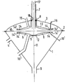
- a vessel comprising a funnel- shaped casing 1 and a cover 3 secured thereto with the aid of a flange 2.
- the interior of the vessel may be filled with compressed gas via a gas supply 4.
- a centrifugal pump is rotatably mounted, which pump comprises a rotor 5 provided on the inside with a number of centrifugal nozzles 6 with an integral hollow shaft 7 in which a feed inlet 17 is mounted.
- the hollow shaft 7 is provided with bearings at 8 in the cover 3 and 18 on the feed inlet 17 and it may be driven with arbitrary means.
- Through the feed inlet 17 powder may be supplied to the centrifugal nozzles 6.
- the vessel further comprises a passage 9 for the discharge of powder from the vessel to a high-pressure reactor (not shown).
- the centrifugal nozzles 6 are directly connected to the hollow shaft 7 and are of a trumpet-shaped longitudinal cross-section. Their longitudinal axes 10 are normal to the axis 11 of the shaft 7 and the feed inlet 17. The total number of centrifugal nozzles 6 is to a certain extent dependent on the required rate of delivery of the centrifugal pump and will preferably vary between 2 and 20.
- a shield 12 is present which is secured to the casing 1 in a manner not shown.
- a shield 13 is also present which is, inter alia, secured near the bearing 8 to the vessel cover 3. Seals 14 seal off the spaces between the rotor 5 and the shields 12 and 13 as much as possible without causing friction.
- a discharge line 15 the upper space may be evacuated, as well as the lower space, via an analogous discharge line 15'.
- the seals 14 are arranged in duplicate, in other words, two concentric rings 14 and 14' are present both in the upper and lower space. The spaces between these rings are connected to supply lines 16 and 16' for hydrogen at a relatively high pressure.
- pulverized coal is introduced at a rate of 10t/h into a centrifugal pump in accordance with the Figure just described which pump is mounted on a coal gasifier.
- a mixture of nitrogen and synthesis gas at approximately 30 atm. is present in the vessel.
- the energy consumption per hour of the centrifugal pump is approximately 150 kW when the pressure and composition of the second and third gas (defined as in the specification preamble) are identical to those of the first gas. If hydrogen at a pressure of approximately 0.01 atm. and 30.5 atm. is used as primary and secondary hydrogen respectively, the energy consumption is only approximately 100 kW.
Landscapes
- Chemical & Material Sciences (AREA)
- Engineering & Computer Science (AREA)
- Organic Chemistry (AREA)
- Chemical Kinetics & Catalysis (AREA)
- Combustion & Propulsion (AREA)
- Oil, Petroleum & Natural Gas (AREA)
- Mechanical Engineering (AREA)
- General Engineering & Computer Science (AREA)
- Structures Of Non-Positive Displacement Pumps (AREA)
- Air Transport Of Granular Materials (AREA)
Claims (4)
Applications Claiming Priority (2)
| Application Number | Priority Date | Filing Date | Title |
|---|---|---|---|
| NL7908314 | 1979-11-14 | ||
| NL7908314 | 1979-11-14 |
Publications (2)
| Publication Number | Publication Date |
|---|---|
| EP0029262A1 EP0029262A1 (fr) | 1981-05-27 |
| EP0029262B1 true EP0029262B1 (fr) | 1984-05-16 |
Family
ID=19834168
Family Applications (1)
| Application Number | Title | Priority Date | Filing Date |
|---|---|---|---|
| EP80200994A Expired EP0029262B1 (fr) | 1979-11-14 | 1980-10-20 | Procédé et dispositif pour alimenter en matière solide finement divisée un réservoir contenant du gaz |
Country Status (7)
| Country | Link |
|---|---|
| US (1) | US4360306A (fr) |
| EP (1) | EP0029262B1 (fr) |
| JP (1) | JPS5682734A (fr) |
| AU (1) | AU533265B2 (fr) |
| CA (1) | CA1153874A (fr) |
| DE (1) | DE3067878D1 (fr) |
| ZA (1) | ZA806985B (fr) |
Families Citing this family (7)
| Publication number | Priority date | Publication date | Assignee | Title |
|---|---|---|---|---|
| GB2114662B (en) * | 1981-11-20 | 1985-03-27 | Shell Int Research | Centrifugal pump for pulverized material |
| US4439200A (en) * | 1981-12-14 | 1984-03-27 | Lockheed Missiles & Space Co., Inc. | Single stage high pressure centrifugal slurry pump |
| GB2356895A (en) * | 1999-06-04 | 2001-06-06 | Russell White | Vacuum pump |
| KR100447007B1 (ko) * | 2002-01-10 | 2004-09-04 | 송죽 테크놀로지(주) | 회전축을 이용한 중앙 투입 장치를 갖는 원심 분리기 |
| US7150474B2 (en) * | 2002-11-12 | 2006-12-19 | Chester Cary | Permanently mounted hose fitting and method for filling tank cars |
| PL2231319T3 (pl) | 2008-01-16 | 2017-06-30 | Shell Internationale Research Maatschappij B.V. | Sposób dostarczania materiału stałego w postaci cząstek do reaktora ciśnieniowego do zgazowywania |
| CN107376722A (zh) * | 2017-08-07 | 2017-11-24 | 成都赛特防水材料有限责任公司 | 一种搅拌桶 |
Family Cites Families (8)
| Publication number | Priority date | Publication date | Assignee | Title |
|---|---|---|---|---|
| DE920234C (de) * | 1952-11-06 | 1954-11-15 | Kuehnle Ag | Verfahren und Vorrichtung zum Schutz der stroemungsfuehrenden Wandungen rotierender Teile gegen Verschleiss durch feste Teile |
| US2822097A (en) * | 1955-08-10 | 1958-02-04 | Us Hoffman Machinery Corp | Centrifugal trickle valve |
| US3182825A (en) * | 1963-08-12 | 1965-05-11 | Koppers Co Inc | Apparatus for transfer of a powdered or granular material from a space under low pressure into a space under high pressure |
| GB1490155A (en) * | 1974-05-15 | 1977-10-26 | Duch B | Device for introducing a material from a first space to a second space against a back pressure |
| NL7504844A (nl) * | 1975-04-24 | 1976-10-26 | Shell Int Research | Werkwijze en inrichting voor het toevoeren van een droog, vrij stromend, koolpoeder aan een hogedruk koolvergassingsreactor. |
| NL7610130A (nl) * | 1976-09-13 | 1978-03-15 | Shell Int Research | Inrichting en werkwijze voor het toevoeren van brandstofpoeder aan een met gas op hoge druk gebracht vat. |
| CH602496A5 (fr) * | 1976-10-08 | 1978-07-31 | Mecafina Sa | |
| US4197092A (en) * | 1978-07-10 | 1980-04-08 | Koppers Company, Inc. | High pressure coal gasifier feeding apparatus |
-
1980
- 1980-09-09 CA CA000359976A patent/CA1153874A/fr not_active Expired
- 1980-10-20 EP EP80200994A patent/EP0029262B1/fr not_active Expired
- 1980-10-20 DE DE8080200994T patent/DE3067878D1/de not_active Expired
- 1980-10-27 US US06/201,256 patent/US4360306A/en not_active Expired - Lifetime
- 1980-11-12 JP JP15832380A patent/JPS5682734A/ja active Pending
- 1980-11-12 ZA ZA00806985A patent/ZA806985B/xx unknown
- 1980-11-12 AU AU64307/80A patent/AU533265B2/en not_active Ceased
Non-Patent Citations (1)
| Title |
|---|
| Hütte, Elektr. Energietechnik, Bd. I, S. 282-283 * |
Also Published As
| Publication number | Publication date |
|---|---|
| CA1153874A (fr) | 1983-09-20 |
| EP0029262A1 (fr) | 1981-05-27 |
| JPS5682734A (en) | 1981-07-06 |
| US4360306A (en) | 1982-11-23 |
| DE3067878D1 (en) | 1984-06-20 |
| AU533265B2 (en) | 1983-11-10 |
| ZA806985B (en) | 1981-11-25 |
| AU6430780A (en) | 1981-05-21 |
Similar Documents
| Publication | Publication Date | Title |
|---|---|---|
| EP2231319B1 (fr) | Procédé d'alimentation d'un réacteur de gazéification en matière solide particulaire | |
| CA1153874A (fr) | Methode et dispositif d'injection de matiere pulverulente dans une chambre chargee de gaz | |
| US4362441A (en) | Means and apparatus for throttling a dry pulverized solid material pump | |
| WO1980002278A1 (fr) | Appareil d'extrusion cinetique: pompe de materiau solide pulverise sec | |
| US4462739A (en) | Dry pulverized solid material pump | |
| US4422809A (en) | Coal pump | |
| US4497605A (en) | Centrifugal pump for transferring solid particles from a low pressure zone into a high pressure zone | |
| AU555844B2 (en) | Dry pulverised solid material pump | |
| FI68981C (fi) | Anordning foer kontinuerlig matning av relativt finfoerdelat material | |
| AU536028B2 (en) | The kinetic extruder: a dry pulverized solid material pump | |
| EP0038597B1 (fr) | Pompe centrifuge pour introduire une matière pulvérulente dans une enceinte sous pression et procédé pour introduire un carburant solide dans un réacteur de gazéification sous haute pression | |
| CA1157393A (fr) | Pompe centrifuge pour l'acheminement de produits pulverulents, et methode de gazeification de la houille | |
| CA1210934A (fr) | Methode et dispositif de preparation d'un melange gazeux combustible, et installation energetique connexe | |
| SU1161187A1 (ru) | Вихрева камера | |
| IE41132B1 (en) | Coal gasification process with improved procedures for continuosly feeding lump coal under pressure and apparatus therefor | |
| US5762760A (en) | Reactor for treating pulp with a gas | |
| AU540431B2 (en) | Apparatus for throttling a dry pulverized solid material pump | |
| SU662133A1 (ru) | Роторный питатель | |
| JPS59500406A (ja) | 乾燥微粉固体材料用ポンプ |
Legal Events
| Date | Code | Title | Description |
|---|---|---|---|
| PUAI | Public reference made under article 153(3) epc to a published international application that has entered the european phase |
Free format text: ORIGINAL CODE: 0009012 |
|
| AK | Designated contracting states |
Designated state(s): DE FR GB NL |
|
| 17P | Request for examination filed |
Effective date: 19811007 |
|
| GRAA | (expected) grant |
Free format text: ORIGINAL CODE: 0009210 |
|
| AK | Designated contracting states |
Designated state(s): DE FR GB NL |
|
| REF | Corresponds to: |
Ref document number: 3067878 Country of ref document: DE Date of ref document: 19840620 |
|
| ET | Fr: translation filed | ||
| PGFP | Annual fee paid to national office [announced via postgrant information from national office to epo] |
Ref country code: FR Payment date: 19840820 Year of fee payment: 5 |
|
| PGFP | Annual fee paid to national office [announced via postgrant information from national office to epo] |
Ref country code: NL Payment date: 19841031 Year of fee payment: 5 |
|
| PGFP | Annual fee paid to national office [announced via postgrant information from national office to epo] |
Ref country code: DE Payment date: 19841115 Year of fee payment: 5 |
|
| PLBE | No opposition filed within time limit |
Free format text: ORIGINAL CODE: 0009261 |
|
| STAA | Information on the status of an ep patent application or granted ep patent |
Free format text: STATUS: NO OPPOSITION FILED WITHIN TIME LIMIT |
|
| 26N | No opposition filed | ||
| PG25 | Lapsed in a contracting state [announced via postgrant information from national office to epo] |
Ref country code: NL Effective date: 19860501 |
|
| PG25 | Lapsed in a contracting state [announced via postgrant information from national office to epo] |
Ref country code: DE Effective date: 19860701 |
|
| NLV4 | Nl: lapsed or anulled due to non-payment of the annual fee | ||
| PG25 | Lapsed in a contracting state [announced via postgrant information from national office to epo] |
Ref country code: FR Free format text: LAPSE BECAUSE OF NON-PAYMENT OF DUE FEES Effective date: 19870630 |
|
| GBPC | Gb: european patent ceased through non-payment of renewal fee | ||
| REG | Reference to a national code |
Ref country code: FR Ref legal event code: ST |
|
| PG25 | Lapsed in a contracting state [announced via postgrant information from national office to epo] |
Ref country code: GB Effective date: 19881118 |