EP0029281A2 - Scirroscope - Google Patents
Scirroscope Download PDFInfo
- Publication number
- EP0029281A2 EP0029281A2 EP80302590A EP80302590A EP0029281A2 EP 0029281 A2 EP0029281 A2 EP 0029281A2 EP 80302590 A EP80302590 A EP 80302590A EP 80302590 A EP80302590 A EP 80302590A EP 0029281 A2 EP0029281 A2 EP 0029281A2
- Authority
- EP
- European Patent Office
- Prior art keywords
- scirroscope
- sheath
- elastic member
- channel
- optical system
- Prior art date
- Legal status (The legal status is an assumption and is not a legal conclusion. Google has not performed a legal analysis and makes no representation as to the accuracy of the status listed.)
- Granted
Links
- 230000003287 optical effect Effects 0.000 claims abstract description 15
- XLYOFNOQVPJJNP-UHFFFAOYSA-N water Substances O XLYOFNOQVPJJNP-UHFFFAOYSA-N 0.000 claims abstract description 6
- 239000004033 plastic Substances 0.000 claims description 5
- 229920003023 plastic Polymers 0.000 claims description 5
- 238000003780 insertion Methods 0.000 abstract description 9
- 230000037431 insertion Effects 0.000 abstract description 9
- 239000000835 fiber Substances 0.000 abstract description 3
- 238000005286 illumination Methods 0.000 abstract description 3
- 230000001954 sterilising effect Effects 0.000 abstract description 3
- 239000013307 optical fiber Substances 0.000 abstract description 2
- 238000004659 sterilization and disinfection Methods 0.000 abstract description 2
- 238000005336 cracking Methods 0.000 abstract 1
- 230000035939 shock Effects 0.000 description 9
- 239000000853 adhesive Substances 0.000 description 4
- 230000001070 adhesive effect Effects 0.000 description 4
- 239000011248 coating agent Substances 0.000 description 4
- 238000000576 coating method Methods 0.000 description 4
- 238000004299 exfoliation Methods 0.000 description 4
- 239000011521 glass Substances 0.000 description 4
- 239000002184 metal Substances 0.000 description 4
- 239000013013 elastic material Substances 0.000 description 3
- 239000000463 material Substances 0.000 description 3
- 238000002788 crimping Methods 0.000 description 2
- 239000003365 glass fiber Substances 0.000 description 2
- 230000003139 buffering effect Effects 0.000 description 1
- 238000010276 construction Methods 0.000 description 1
- 238000006073 displacement reaction Methods 0.000 description 1
- 230000001681 protective effect Effects 0.000 description 1
Images

Classifications
-
- A—HUMAN NECESSITIES
- A61—MEDICAL OR VETERINARY SCIENCE; HYGIENE
- A61B—DIAGNOSIS; SURGERY; IDENTIFICATION
- A61B1/00—Instruments for performing medical examinations of the interior of cavities or tubes of the body by visual or photographical inspection, e.g. endoscopes; Illuminating arrangements therefor
- A61B1/00163—Optical arrangements
- A61B1/00165—Optical arrangements with light-conductive means, e.g. fibre optics
- A61B1/00167—Details of optical fibre bundles, e.g. shape or fibre distribution
-
- A—HUMAN NECESSITIES
- A61—MEDICAL OR VETERINARY SCIENCE; HYGIENE
- A61B—DIAGNOSIS; SURGERY; IDENTIFICATION
- A61B1/00—Instruments for performing medical examinations of the interior of cavities or tubes of the body by visual or photographical inspection, e.g. endoscopes; Illuminating arrangements therefor
- A61B1/002—Instruments for performing medical examinations of the interior of cavities or tubes of the body by visual or photographical inspection, e.g. endoscopes; Illuminating arrangements therefor having rod-lens arrangements
-
- A—HUMAN NECESSITIES
- A61—MEDICAL OR VETERINARY SCIENCE; HYGIENE
- A61B—DIAGNOSIS; SURGERY; IDENTIFICATION
- A61B1/00—Instruments for performing medical examinations of the interior of cavities or tubes of the body by visual or photographical inspection, e.g. endoscopes; Illuminating arrangements therefor
- A61B1/12—Instruments for performing medical examinations of the interior of cavities or tubes of the body by visual or photographical inspection, e.g. endoscopes; Illuminating arrangements therefor with cooling or rinsing arrangements
Definitions
- the invention relates to a scirroscope, namely, an endoscope having a rigid and straight sheath or shell tube.
- a scirroscope has a disadvantage that it is susceptible to shocks because of principal materials such as metal or glass which are used to form it. In particular, if it is dropped inadvertently during use, it is likely that the shocks applied will cause a misalignment of the optical system or a water leakage.
- a scirroscope includes tubes and other parts which are directly joined to each other by adhesives. These parts exhibit different coefficients of thermal expansion, which may give rise to exfoliation if the scirroscope is sterilized under heat or cleaned with hot water.
- a scirroscope including an observation and an illuminaticn optical system both disposed in a sheath characterized by an elastic member which coats the internal periphery of the sheath and/or the external periphery of at least one internally housed part.
- a coating of an elastic material such as rubber or plastics on the internal or external periphery of a sheath or shell tube, optics tube, channel and optical fibre bundle, which form a portion of a scirroscope adapted to be inserted into a coeliac cavity and which are of materials such as glass, metal and glass fibre, is effective to attenuate any external shock, which may be produced as a result of being dropped during use, as it is transmitted to an inner parL or parts, thus avoiding a misalignment of the optical system or breakage of lenses.
- the elastic material such as rubber or plastics exhibits a lower thermal conductivity, minimizing the conduction of heat to the interior if heat is applied to the scirroscope when sterilizing it in an autoclave or other equipment.
- the resilience of the elastic material accommodate for some differences in the coefficient of thermal expansion between the parts, thus acting as a buffering element therebetween to eliminate the occurrence of.exfoliation or cracks.
- Fig.l illustrates a conventional scirroscope 1, including a portion 2A adapted to be inserted into a coeliac cavity and an operating end 2B.
- the portion 2A comprises a shell tube or sheath 3 formed of a metal and configured as a pipe in which are disposed a channel 4 for feeding water or passing a treatment instrument or the like, and an optical tube 6 having an observation optical system 5 disposed therein as well as an illumination optical system 8, formed by a bundle of optical fibres 7.
- the observation system 5 includes a protective .glass 9 attached to its distal end, and a plurality of lenses 10 which are disposed in the tube 6 and are used to project an image being observed.
- the operating end 2B comprises an observation eyepiece assembly 11, a fixture 12 for an illumination light guide, and a fitting 13 for connection with a hose which is used to feed water into the channel 4 and having a feedwater control cock 14 associated therewith.
- Parts of the insertion portion 2A are formed of metal, glass, glass fibre and like materials which are susceptible to damage by shock. Additionally, these parts are directly joined to each other by adhesives, and this causes any externally applied shock to be directly transmitted to objects located within them, with consequences that the optical axis of the optical system may be misaligned and the lenses broken. Also, a relative displacement between the parts as well as cracks in them are caused by different coefficients of thermal expansion thereof.
- Figs. 2(a) and (b) are sections of essential parts of an insertion portion 20 of a scirroscope according to one embodiment of the invention which is adapted to be inserted into a coeliac cavity.
- Corresponding parts to those shown in Fig.l are designated by like reference characters, and hence will not be further described.
- An elastic member 21 is integrally bonded, as by adhesive or crimping, to the internal periphery of the sheath 3 of the insertion portion 20, and an adhesive is applied to the interface between the internal periphery of the elastic member and another member which contacts it, such as the optics tube 6 and the fibre bundle 7.
- such inner member is integrally bonded to the elastic member 21 as by adhesion or crimping.
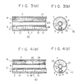
- Figs. 3(a) and (b) show another embodiment of the invention where an insertion portion 30 of scirroscope shown is provided with a coating in the form of an elastic member applied to the inner periphery of the sheath 3, in the same manner as shown in Fig.2. Additionally, it is provided with elastic members 22 and 23 on the outer periphery of the optics tube 6 and the channel 4, respectively. Other parts correspond to those shown in Figs. 1 and 2.
- the insertion portion 30 is provided with elastic members 21, 22, 23, formed of rubber, plastics or the like, which coat the internal periphery of the sheath 3 and the external periphery of the optics tube 6 and the channel 4, the insertion portion 30 exhibits a heat and shock resistance which are comparable to or even exceed those of the insertion portion 20 shown in Fig.2.
- Figs. 4(a) and (b) show a further embodiment of the invention where an insertion portion 40 of scirroscope which is adapted to be inserted into a coeliac cavity is provided with a plurality of ring-shaped elastic members 24 coating the external periphery of the optics tube 6, a plurality of tubular elastic members 25 of a reduced length coating the external periphery of both the fibre bundle 7 and the channel 4, and an elastic member 26 in a trapezoidal form and having a reduced length covering one- half the external periphery of the channel 4.
- corresponding parts to those shown in Figs. 2 and 3 are designated by like reference characters and will not be described.
Landscapes
- Health & Medical Sciences (AREA)
- Life Sciences & Earth Sciences (AREA)
- Surgery (AREA)
- Optics & Photonics (AREA)
- Physics & Mathematics (AREA)
- Biomedical Technology (AREA)
- Animal Behavior & Ethology (AREA)
- Radiology & Medical Imaging (AREA)
- Nuclear Medicine, Radiotherapy & Molecular Imaging (AREA)
- Engineering & Computer Science (AREA)
- Biophysics (AREA)
- Heart & Thoracic Surgery (AREA)
- Medical Informatics (AREA)
- Molecular Biology (AREA)
- Pathology (AREA)
- General Health & Medical Sciences (AREA)
- Public Health (AREA)
- Veterinary Medicine (AREA)
- Endoscopes (AREA)
- Pyrane Compounds (AREA)
- Steroid Compounds (AREA)
- Photoreceptors In Electrophotography (AREA)
- Instruments For Viewing The Inside Of Hollow Bodies (AREA)
Abstract
Description
- The invention relates to a scirroscope, namely, an endoscope having a rigid and straight sheath or shell tube.
- A scirroscope has a disadvantage that it is susceptible to shocks because of principal materials such as metal or glass which are used to form it. In particular, if it is dropped inadvertently during use, it is likely that the shocks applied will cause a misalignment of the optical system or a water leakage. A scirroscope includes tubes and other parts which are directly joined to each other by adhesives. These parts exhibit different coefficients of thermal expansion, which may give rise to exfoliation if the scirroscope is sterilized under heat or cleaned with hot water.
- It is an object of the invention to eliminate above disadvantages, by providing a scirroscope which is of more robust construction and less prone to experiencing extreme temperature gradients during sterilization.
- In accordance with the present invention, there is provided a scirroscope including an observation and an illuminaticn optical system both disposed in a sheath characterized by an elastic member which coats the internal periphery of the sheath and/or the external periphery of at least one internally housed part.
- The provision of a coating of an elastic material such as rubber or plastics on the internal or external periphery of a sheath or shell tube, optics tube, channel and optical fibre bundle, which form a portion of a scirroscope adapted to be inserted into a coeliac cavity and which are of materials such as glass, metal and glass fibre, is effective to attenuate any external shock, which may be produced as a result of being dropped during use, as it is transmitted to an inner parL or parts, thus avoiding a misalignment of the optical system or breakage of lenses. The elastic material such as rubber or plastics exhibits a lower thermal conductivity, minimizing the conduction of heat to the interior if heat is applied to the scirroscope when sterilizing it in an autoclave or other equipment. The resilience of the elastic material accommodate for some differences in the coefficient of thermal expansion between the parts, thus acting as a buffering element therebetween to eliminate the occurrence of.exfoliation or cracks.
- The invention is further described, by way of example, with reference to the drawings, in which:-
- Fig.l is a side elevation of an example of a conventional scirroscope, with a portion to be inserted into a coeliac cavity shown in section; and
- Figs. 2 to 4, (a) and (b) are respective axial and transverse sections of several embodiments of the invention, respectively.
- Fig.l illustrates a conventional scirroscope 1, including a
portion 2A adapted to be inserted into a coeliac cavity and an operatingend 2B. Theportion 2A comprises a shell tube orsheath 3 formed of a metal and configured as a pipe in which are disposed achannel 4 for feeding water or passing a treatment instrument or the like, and anoptical tube 6 having an observationoptical system 5 disposed therein as well as an illuminationoptical system 8, formed by a bundle ofoptical fibres 7. Theobservation system 5 includes a protective .glass 9 attached to its distal end, and a plurality oflenses 10 which are disposed in thetube 6 and are used to project an image being observed. The operatingend 2B comprises an observation eyepiece assembly 11, afixture 12 for an illumination light guide, and afitting 13 for connection with a hose which is used to feed water into thechannel 4 and having afeedwater control cock 14 associated therewith. - Parts of the
insertion portion 2A are formed of metal, glass, glass fibre and like materials which are susceptible to damage by shock. Additionally, these parts are directly joined to each other by adhesives, and this causes any externally applied shock to be directly transmitted to objects located within them, with consequences that the optical axis of the optical system may be misaligned and the lenses broken. Also, a relative displacement between the parts as well as cracks in them are caused by different coefficients of thermal expansion thereof. - Figs. 2(a) and (b) are sections of essential parts of an
insertion portion 20 of a scirroscope according to one embodiment of the invention which is adapted to be inserted into a coeliac cavity. Corresponding parts to those shown in Fig.l are designated by like reference characters, and hence will not be further described. - An
elastic member 21 is integrally bonded, as by adhesive or crimping, to the internal periphery of thesheath 3 of theinsertion portion 20, and an adhesive is applied to the interface between the internal periphery of the elastic member and another member which contacts it, such as theoptics tube 6 and thefibre bundle 7. - In this manner, such inner member is integrally bonded to the
elastic member 21 as by adhesion or crimping. - The presence of the
elastic member 21, which absorbs some of the shock applied to thesheath 3, as might be produced if the latter is dropped, minimizes the influence of the shock upon internal parts, thus minimizing the likelihood that theoptical system 5 may be damaged. The reduced thermal conductivity of theelastic member 21, formed by rubber, plastics or the like, retards the heat transfer to the interior, whereby a temperature gradient which causes an exfoliation or cracks is advantageously reduced. - Figs. 3(a) and (b) show another embodiment of the invention where an
insertion portion 30 of scirroscope shown is provided with a coating in the form of an elastic member applied to the inner periphery of thesheath 3, in the same manner as shown in Fig.2. Additionally, it is provided withelastic members optics tube 6 and thechannel 4, respectively. Other parts correspond to those shown in Figs. 1 and 2. - Since the
insertion portion 30 is provided withelastic members sheath 3 and the external periphery of theoptics tube 6 and thechannel 4, theinsertion portion 30 exhibits a heat and shock resistance which are comparable to or even exceed those of theinsertion portion 20 shown in Fig.2. - Figs. 4(a) and (b) show a further embodiment of the invention where an
insertion portion 40 of scirroscope which is adapted to be inserted into a coeliac cavity is provided with a plurality of ring-shapedelastic members 24 coating the external periphery of theoptics tube 6, a plurality of tubularelastic members 25 of a reduced length coating the external periphery of both thefibre bundle 7 and thechannel 4, and anelastic member 26 in a trapezoidal form and having a reduced length covering one- half the external periphery of thechannel 4. Again, corresponding parts to those shown in Figs. 2 and 3 are designated by like reference characters and will not be described. - The use of several
elastic members
Claims (4)
Priority Applications (1)
| Application Number | Priority Date | Filing Date | Title |
|---|---|---|---|
| AT80302590T ATE8328T1 (en) | 1979-11-20 | 1980-07-30 | ENDOSCOPE. |
Applications Claiming Priority (2)
| Application Number | Priority Date | Filing Date | Title |
|---|---|---|---|
| JP150521/79 | 1979-11-20 | ||
| JP15052179A JPS5672839A (en) | 1979-11-20 | 1979-11-20 | Hard mirror |
Publications (3)
| Publication Number | Publication Date |
|---|---|
| EP0029281A2 true EP0029281A2 (en) | 1981-05-27 |
| EP0029281A3 EP0029281A3 (en) | 1982-03-10 |
| EP0029281B1 EP0029281B1 (en) | 1984-07-11 |
Family
ID=15498673
Family Applications (1)
| Application Number | Title | Priority Date | Filing Date |
|---|---|---|---|
| EP80302590A Expired EP0029281B1 (en) | 1979-11-20 | 1980-07-30 | Scirroscope |
Country Status (5)
| Country | Link |
|---|---|
| US (1) | US4361139A (en) |
| EP (1) | EP0029281B1 (en) |
| JP (1) | JPS5672839A (en) |
| AT (1) | ATE8328T1 (en) |
| DE (1) | DE3068520D1 (en) |
Cited By (5)
| Publication number | Priority date | Publication date | Assignee | Title |
|---|---|---|---|---|
| EP0032595A3 (en) * | 1980-01-17 | 1982-03-10 | Olympus Optical Co., Ltd. | Endoscope |
| EP0086883A1 (en) * | 1981-12-11 | 1983-08-31 | Carlos Maria Pichel Moure | Osteoscope for carrying out the nailing of the fractures |
| FR2575382A1 (en) * | 1985-01-03 | 1986-07-04 | Kaltenbach & Voigt | DENTAL HANDPIECE |
| EP0292602A1 (en) * | 1987-05-26 | 1988-11-30 | Storz, Karl, Dr.med. h.c. | Optical endoscope |
| US4879991A (en) * | 1986-11-12 | 1989-11-14 | Olympus Optical Co., Ltd. | Endoscope |
Families Citing this family (16)
| Publication number | Priority date | Publication date | Assignee | Title |
|---|---|---|---|---|
| JPS5812642A (en) * | 1981-07-16 | 1983-01-24 | オリンパス光学工業株式会社 | Hard endoscope |
| US4718406A (en) * | 1982-06-28 | 1988-01-12 | The United States Of America As Represented By The Secretary Of The Navy | Fiber optics image scope (micro-endoscope), ureteroscope |
| EP0100517B1 (en) * | 1982-07-31 | 1990-12-27 | Sumitomo Electric Industries Limited | Optical fiber sensor |
| JPS60125610U (en) * | 1984-02-03 | 1985-08-24 | オリンパス光学工業株式会社 | Strabismus-type rigid endoscope |
| US5470330A (en) * | 1984-12-07 | 1995-11-28 | Advanced Interventional Systems, Inc. | Guidance and delivery system for high-energy pulsed laser light |
| US5989243A (en) * | 1984-12-07 | 1999-11-23 | Advanced Interventional Systems, Inc. | Excimer laser angioplasty system |
| JPH0531613Y2 (en) * | 1986-05-14 | 1993-08-13 | ||
| US5030217A (en) * | 1988-04-14 | 1991-07-09 | Heraeus Lasersonics, Inc. | Medical laser probe and method of delivering CO2 radiation |
| US4911712A (en) * | 1988-04-14 | 1990-03-27 | Heraeus Lasersonics, Inc. | Medical laser probe |
| JPH01276112A (en) * | 1988-04-28 | 1989-11-06 | Olympus Optical Co Ltd | Endoscope |
| JPH0638901U (en) * | 1992-10-29 | 1994-05-24 | 富士写真光機株式会社 | Endoscope device |
| JPH07303625A (en) * | 1994-03-18 | 1995-11-21 | Olympus Optical Co Ltd | Instrument for magnetic resonance tomography device |
| US5632717A (en) * | 1994-10-07 | 1997-05-27 | Yoon; Inbae | Penetrating endoscope |
| DE4438944C2 (en) * | 1994-10-31 | 2003-10-09 | Wolf Gmbh Richard | endoscope |
| DE19743431B4 (en) | 1997-10-01 | 2011-02-17 | Karl Storz Gmbh & Co. Kg | Endoscope with composite window |
| US6328730B1 (en) * | 1999-03-26 | 2001-12-11 | William W. Harkrider, Jr. | Endoluminal multi-luminal surgical sheath and method |
Family Cites Families (11)
| Publication number | Priority date | Publication date | Assignee | Title |
|---|---|---|---|---|
| US3010357A (en) * | 1956-12-28 | 1961-11-28 | Wilbur Peters C | Flexible light transmitting tube |
| US3091235A (en) * | 1960-06-15 | 1963-05-28 | American Optical Corp | Diagnostic instruments |
| FR1347596A (en) * | 1963-02-19 | 1963-12-27 | Flexible tube for endoscopes | |
| US3434775A (en) * | 1965-04-23 | 1969-03-25 | Iota Cam Corp | Flexible fiber optic borescope |
| FR1562267A (en) * | 1968-02-23 | 1969-04-04 | ||
| JPS4914996B1 (en) * | 1969-02-07 | 1974-04-11 | ||
| US3776222A (en) * | 1971-12-23 | 1973-12-04 | Lurosso A | Fiber optic entubator and method of entubation of the trachea through the nasopharynx |
| US3939839A (en) * | 1974-06-26 | 1976-02-24 | American Cystoscope Makers, Inc. | Resectoscope and electrode therefor |
| JPS6024323Y2 (en) * | 1977-02-10 | 1985-07-20 | オリンパス光学工業株式会社 | Flexible tube for endoscope |
| US4148550A (en) * | 1977-05-09 | 1979-04-10 | American Hospital Supply Corporation | Rod lens assembly and method of making the same |
| US4173392A (en) * | 1977-07-20 | 1979-11-06 | American Hospital Supply Corporation | Glass fiber light guide and method of making the same |
-
1979
- 1979-11-20 JP JP15052179A patent/JPS5672839A/en active Pending
-
1980
- 1980-07-30 AT AT80302590T patent/ATE8328T1/en not_active IP Right Cessation
- 1980-07-30 EP EP80302590A patent/EP0029281B1/en not_active Expired
- 1980-07-30 DE DE8080302590T patent/DE3068520D1/en not_active Expired
- 1980-07-31 US US06/174,236 patent/US4361139A/en not_active Expired - Lifetime
Cited By (5)
| Publication number | Priority date | Publication date | Assignee | Title |
|---|---|---|---|---|
| EP0032595A3 (en) * | 1980-01-17 | 1982-03-10 | Olympus Optical Co., Ltd. | Endoscope |
| EP0086883A1 (en) * | 1981-12-11 | 1983-08-31 | Carlos Maria Pichel Moure | Osteoscope for carrying out the nailing of the fractures |
| FR2575382A1 (en) * | 1985-01-03 | 1986-07-04 | Kaltenbach & Voigt | DENTAL HANDPIECE |
| US4879991A (en) * | 1986-11-12 | 1989-11-14 | Olympus Optical Co., Ltd. | Endoscope |
| EP0292602A1 (en) * | 1987-05-26 | 1988-11-30 | Storz, Karl, Dr.med. h.c. | Optical endoscope |
Also Published As
| Publication number | Publication date |
|---|---|
| EP0029281A3 (en) | 1982-03-10 |
| US4361139A (en) | 1982-11-30 |
| EP0029281B1 (en) | 1984-07-11 |
| JPS5672839A (en) | 1981-06-17 |
| ATE8328T1 (en) | 1984-07-15 |
| DE3068520D1 (en) | 1984-08-16 |
Similar Documents
| Publication | Publication Date | Title |
|---|---|---|
| EP0029281B1 (en) | Scirroscope | |
| EP0027185B1 (en) | Protective covering for the bend section of an endoscope | |
| US3699950A (en) | Flexible optical light pipes used for surgery | |
| US4870952A (en) | Fiber optic illuminator for use in surgery | |
| US6398723B1 (en) | Endoscope having an immobilization system for components of an inner optical system | |
| EP0032595B1 (en) | Endoscope | |
| CA1098746A (en) | Modular rod lens assembly and method of making the same | |
| US7662096B2 (en) | Method for assembling an endoscope | |
| US6019719A (en) | Fully autoclavable electronic endoscope | |
| EP0069389B1 (en) | Manipulator for laser knife | |
| US5944656A (en) | Endoscope | |
| US5349941A (en) | Cleanable endoscope | |
| US5396366A (en) | Endoscope apparatus | |
| US4697870A (en) | Termination for light-conducting cable | |
| US12455413B2 (en) | Fiber-optic light guide with deformed ends | |
| KR100287509B1 (en) | Engaged base end connector for mounting fiber optic elements in a light source system | |
| US6572536B1 (en) | Autoclavable flexible fiberscope | |
| US3357423A (en) | Surgical light pipe and the like | |
| US4063796A (en) | Optical device for an endoscope with bellows expansion compensation means | |
| WO1996005764A2 (en) | Endoscope | |
| US4776668A (en) | Image focusing ocular piece for a viewing scope including mechanism for accommodating differential expansion | |
| US6997868B1 (en) | Autoclavable endoscope | |
| JP2000121962A (en) | Endoscope | |
| US5764837A (en) | Snap-in proximal connector for mounting an optic fiber element into a light source system | |
| EP1662967A1 (en) | Endoscope |
Legal Events
| Date | Code | Title | Description |
|---|---|---|---|
| PUAI | Public reference made under article 153(3) epc to a published international application that has entered the european phase |
Free format text: ORIGINAL CODE: 0009012 |
|
| AK | Designated contracting states |
Designated state(s): AT BE CH DE FR GB IT NL SE |
|
| PUAL | Search report despatched |
Free format text: ORIGINAL CODE: 0009013 |
|
| RHK1 | Main classification (correction) |
Ipc: A61B 1/00 |
|
| AK | Designated contracting states |
Designated state(s): AT BE CH DE FR GB IT NL SE |
|
| 17P | Request for examination filed |
Effective date: 19820618 |
|
| GRAA | (expected) grant |
Free format text: ORIGINAL CODE: 0009210 |
|
| AK | Designated contracting states |
Designated state(s): AT BE CH DE FR GB IT LI NL SE |
|
| PG25 | Lapsed in a contracting state [announced via postgrant information from national office to epo] |
Ref country code: SE Effective date: 19840711 Ref country code: NL Effective date: 19840711 Ref country code: LI Effective date: 19840711 Ref country code: IT Free format text: LAPSE BECAUSE OF FAILURE TO SUBMIT A TRANSLATION OF THE DESCRIPTION OR TO PAY THE FEE WITHIN THE PRESCRIBED TIME-LIMIT;WARNING: LAPSES OF ITALIAN PATENTS WITH EFFECTIVE DATE BEFORE 2007 MAY HAVE OCCURRED AT ANY TIME BEFORE 2007. THE CORRECT EFFECTIVE DATE MAY BE DIFFERENT FROM THE ONE RECORDED. Effective date: 19840711 Ref country code: FR Free format text: THE PATENT HAS BEEN ANNULLED BY A DECISION OF A NATIONAL AUTHORITY Effective date: 19840711 Ref country code: CH Effective date: 19840711 Ref country code: BE Effective date: 19840711 Ref country code: AT Effective date: 19840711 |
|
| REF | Corresponds to: |
Ref document number: 8328 Country of ref document: AT Date of ref document: 19840715 Kind code of ref document: T |
|
| REF | Corresponds to: |
Ref document number: 3068520 Country of ref document: DE Date of ref document: 19840816 |
|
| REG | Reference to a national code |
Ref country code: CH Ref legal event code: PL |
|
| NLV1 | Nl: lapsed or annulled due to failure to fulfill the requirements of art. 29p and 29m of the patents act | ||
| GBPC | Gb: european patent ceased through non-payment of renewal fee | ||
| PLBE | No opposition filed within time limit |
Free format text: ORIGINAL CODE: 0009261 |
|
| STAA | Information on the status of an ep patent application or granted ep patent |
Free format text: STATUS: NO OPPOSITION FILED WITHIN TIME LIMIT |
|
| 26N | No opposition filed | ||
| EN | Fr: translation not filed | ||
| PG25 | Lapsed in a contracting state [announced via postgrant information from national office to epo] |
Ref country code: GB Effective date: 19881118 |
|
| PGFP | Annual fee paid to national office [announced via postgrant information from national office to epo] |
Ref country code: DE Payment date: 19900831 Year of fee payment: 11 |
|
| PG25 | Lapsed in a contracting state [announced via postgrant information from national office to epo] |
Ref country code: DE Effective date: 19920401 |