EP0029349A2 - Appareil de mesure automatique de la pression sanguine - Google Patents
Appareil de mesure automatique de la pression sanguine Download PDFInfo
- Publication number
- EP0029349A2 EP0029349A2 EP80304068A EP80304068A EP0029349A2 EP 0029349 A2 EP0029349 A2 EP 0029349A2 EP 80304068 A EP80304068 A EP 80304068A EP 80304068 A EP80304068 A EP 80304068A EP 0029349 A2 EP0029349 A2 EP 0029349A2
- Authority
- EP
- European Patent Office
- Prior art keywords
- pressure
- cuff
- signal
- index
- subject
- Prior art date
- Legal status (The legal status is an assumption and is not a legal conclusion. Google has not performed a legal analysis and makes no representation as to the accuracy of the status listed.)
- Granted
Links
- 230000036772 blood pressure Effects 0.000 title claims abstract description 23
- 238000000034 method Methods 0.000 claims abstract description 41
- 230000035487 diastolic blood pressure Effects 0.000 claims abstract description 24
- 230000035488 systolic blood pressure Effects 0.000 claims abstract description 23
- 238000012545 processing Methods 0.000 claims abstract description 11
- 230000000747 cardiac effect Effects 0.000 claims abstract description 5
- 230000007423 decrease Effects 0.000 claims abstract description 5
- 230000001419 dependent effect Effects 0.000 claims abstract description 4
- 238000005259 measurement Methods 0.000 claims description 9
- 230000003247 decreasing effect Effects 0.000 claims description 6
- 230000004217 heart function Effects 0.000 claims description 4
- 238000005070 sampling Methods 0.000 claims description 4
- 230000002123 temporal effect Effects 0.000 claims description 3
- 238000009877 rendering Methods 0.000 claims description 2
- FGUUSXIOTUKUDN-IBGZPJMESA-N C1(=CC=CC=C1)N1C2=C(NC([C@H](C1)NC=1OC(=NN=1)C1=CC=CC=C1)=O)C=CC=C2 Chemical compound C1(=CC=CC=C1)N1C2=C(NC([C@H](C1)NC=1OC(=NN=1)C1=CC=CC=C1)=O)C=CC=C2 FGUUSXIOTUKUDN-IBGZPJMESA-N 0.000 claims 1
- 239000000872 buffer Substances 0.000 description 24
- 238000001514 detection method Methods 0.000 description 8
- 230000008569 process Effects 0.000 description 8
- 238000013459 approach Methods 0.000 description 7
- 210000001367 artery Anatomy 0.000 description 4
- 230000003205 diastolic effect Effects 0.000 description 4
- 230000006870 function Effects 0.000 description 4
- 238000012544 monitoring process Methods 0.000 description 4
- 238000009825 accumulation Methods 0.000 description 3
- 230000017531 blood circulation Effects 0.000 description 3
- 238000009530 blood pressure measurement Methods 0.000 description 3
- 230000008859 change Effects 0.000 description 3
- 230000003750 conditioning effect Effects 0.000 description 3
- 230000008602 contraction Effects 0.000 description 3
- 230000009471 action Effects 0.000 description 2
- 210000002302 brachial artery Anatomy 0.000 description 2
- 230000000694 effects Effects 0.000 description 2
- 230000008030 elimination Effects 0.000 description 2
- 238000003379 elimination reaction Methods 0.000 description 2
- 238000001914 filtration Methods 0.000 description 2
- 230000001788 irregular Effects 0.000 description 2
- 210000003205 muscle Anatomy 0.000 description 2
- 230000037081 physical activity Effects 0.000 description 2
- 238000005086 pumping Methods 0.000 description 2
- 238000001228 spectrum Methods 0.000 description 2
- 238000012935 Averaging Methods 0.000 description 1
- 238000010521 absorption reaction Methods 0.000 description 1
- 230000006978 adaptation Effects 0.000 description 1
- 238000010420 art technique Methods 0.000 description 1
- 230000001746 atrial effect Effects 0.000 description 1
- 238000011511 automated evaluation Methods 0.000 description 1
- 238000005452 bending Methods 0.000 description 1
- 230000033228 biological regulation Effects 0.000 description 1
- 239000008280 blood Substances 0.000 description 1
- 210000004369 blood Anatomy 0.000 description 1
- 230000004087 circulation Effects 0.000 description 1
- 238000004891 communication Methods 0.000 description 1
- 230000001143 conditioned effect Effects 0.000 description 1
- 238000013270 controlled release Methods 0.000 description 1
- 230000008878 coupling Effects 0.000 description 1
- 238000010168 coupling process Methods 0.000 description 1
- 238000005859 coupling reaction Methods 0.000 description 1
- 230000002999 depolarising effect Effects 0.000 description 1
- 238000006073 displacement reaction Methods 0.000 description 1
- 238000011156 evaluation Methods 0.000 description 1
- 210000001308 heart ventricle Anatomy 0.000 description 1
- 230000010365 information processing Effects 0.000 description 1
- 238000011835 investigation Methods 0.000 description 1
- 230000003278 mimic effect Effects 0.000 description 1
- 230000003387 muscular Effects 0.000 description 1
- 230000035479 physiological effects, processes and functions Effects 0.000 description 1
- 238000011084 recovery Methods 0.000 description 1
- 230000000306 recurrent effect Effects 0.000 description 1
- 230000034225 regulation of ventricular cardiomyocyte membrane depolarization Effects 0.000 description 1
- 230000001105 regulatory effect Effects 0.000 description 1
- 230000002336 repolarization Effects 0.000 description 1
- 230000000630 rising effect Effects 0.000 description 1
- 230000035939 shock Effects 0.000 description 1
- 238000009662 stress testing Methods 0.000 description 1
- 230000001960 triggered effect Effects 0.000 description 1
- 238000002604 ultrasonography Methods 0.000 description 1
- 230000002792 vascular Effects 0.000 description 1
Images

Classifications
-
- A—HUMAN NECESSITIES
- A61—MEDICAL OR VETERINARY SCIENCE; HYGIENE
- A61B—DIAGNOSIS; SURGERY; IDENTIFICATION
- A61B5/00—Measuring for diagnostic purposes; Identification of persons
- A61B5/02—Detecting, measuring or recording for evaluating the cardiovascular system, e.g. pulse, heart rate, blood pressure or blood flow
- A61B5/021—Measuring pressure in heart or blood vessels
- A61B5/022—Measuring pressure in heart or blood vessels by applying pressure to close blood vessels, e.g. against the skin; Ophthalmodynamometers
- A61B5/02208—Measuring pressure in heart or blood vessels by applying pressure to close blood vessels, e.g. against the skin; Ophthalmodynamometers using the Korotkoff method
-
- A—HUMAN NECESSITIES
- A61—MEDICAL OR VETERINARY SCIENCE; HYGIENE
- A61B—DIAGNOSIS; SURGERY; IDENTIFICATION
- A61B5/00—Measuring for diagnostic purposes; Identification of persons
- A61B5/24—Detecting, measuring or recording bioelectric or biomagnetic signals of the body or parts thereof
- A61B5/316—Modalities, i.e. specific diagnostic methods
- A61B5/318—Heart-related electrical modalities, e.g. electrocardiography [ECG]
- A61B5/346—Analysis of electrocardiograms
- A61B5/349—Detecting specific parameters of the electrocardiograph cycle
- A61B5/352—Detecting R peaks, e.g. for synchronising diagnostic apparatus; Estimating R-R interval
-
- A—HUMAN NECESSITIES
- A61—MEDICAL OR VETERINARY SCIENCE; HYGIENE
- A61B—DIAGNOSIS; SURGERY; IDENTIFICATION
- A61B5/00—Measuring for diagnostic purposes; Identification of persons
- A61B5/72—Signal processing specially adapted for physiological signals or for diagnostic purposes
- A61B5/7271—Specific aspects of physiological measurement analysis
- A61B5/7285—Specific aspects of physiological measurement analysis for synchronizing or triggering a physiological measurement or image acquisition with a physiological event or waveform, e.g. an ECG signal
Definitions
- This invention relates to automated evaluation of blood pressure, and more particularly to the automatic evaluation of blood pressure of a subject under physical stress, such as exercise.
- the most conventional and time-honored method for obtaining blood pressure is the manual ausculatory, method, wherein a cuff is inflated to arrest blood flow in a limb, after which the pressure is slowly decreased.
- the clinician such as by means of a stethoscope, listens to sounds occurring in the limb at a point distal to the cuff, for example at the brachial artery. Re-establishment of circulation is accompanied by pulsating sounds, known as Korotkoff sounds, and the cuff pressures substantially at the beginning and the end of occurrence of these Korotkoff sounds are noted by the clinician as systolic and diastolic blood pressures, respectively.
- ECG gating Another approach to the problem of signal discrimination and noise elimination has been the employment of ECG gating. That is, electrocardiograph electrodes are placed on the subject, allowing for an ongoing monitoring of the "PQRST" cardiac complex. Since Korotkoff sounds result from a rush of arterial blood being pumped through an artery, a knowledge of the moment-to-moment condition of the heart will correspondingly identify but a limited portion of time during which the Korotkoff sound cbuld occur. ECG gating techniques have provided a viable and at times valuable approach to blood pressure measurement for a quiescent or stationary subject, but for a subject during exercise, they provide no substantial relief to the problem of elimination of previously described artifact data.
- the present invention is grounded on the proposition that numerous prior art techniques, such as incremental cuff deflation, sonic monitoring of arterial condition, ECG gating, and digital signal processing techniques, may be combined, improved, and built upon to yield a technique which rapidly and accurately measures blood pressure during periods of intense physical exercise, with relatively minimal inconvenience or discomfort to the subject.
- numerous prior art techniques such as incremental cuff deflation, sonic monitoring of arterial condition, ECG gating, and digital signal processing techniques
- the principles of the present invention utilize in part a digital signal processing technique known as non-phase-coherent correlation detection.
- This technique is set forth in general terms in "Comparison of Phase-Coherent and Non-Phase-Coherent Coded Communications" by J. P. Strong and T. V. Seliga, Goddard Space Flt. Ctr. Publication No. X-711-65-425, Oct. 1965, and generally involves repeated signal sampling at respective times of low and high probability of occurrence of a signal to be sampled, individual processing of the respective sample sets, and a comparison of the results of such processing.
- the technique effectively develops separate indices or representations of noise, and signal (if any) plus noise, with the consequent ability to identify the differential index comprising signal.
- ECG electrodes e.g. three in number
- a pressure cuff having a microphone on its interior surface is placed on a limb (e.g. the arm) of the subject, with the microphone positioned for sonic monitoring of arterial noises.
- the cuff is coupled to a pump through a reservoir of substantial volume, which tends to minimize spurious pressure changes due,to volumetric changes in the cuff occasioned by muscle flexing and the like.
- the cuff is pumped to a pressure above systolic (e.g.
- each cardiac R-wave is utilized to enable or gate several samplings of the microphone signal, including accumulating a first plurality of signals, (e:g. sixteen samples occurring just before and after the R-wave), and a subsequent, second plurality of samples (e.g. thirty-two samples occurring a predetermined time subsequent to the first plurality).
- a first plurality of signals e:g. sixteen samples occurring just before and after the R-wave
- a subsequent, second plurality of samples e.g. thirty-two samples occurring a predetermined time subsequent to the first plurality.
- the first plurality is assembled by suitable averaging techniques to a first index, indicative of noise, and the second plurality is likewise processed to yield a second index indicative of signal (if any) plus noise.
- the cuff pressure level at which the second index exceeds the first by a predetermined amount is identified as the first level at which Korotkoff sound has occurred, in other words, systolic pressure.
- detection of systolic is verified by a repetition of the process at the next decrement, but in any event, once systolic pressure is identified with certainty, the process is continued in similar fashion for detection of diastolic pressure.
- the key to detection of diastolic pressure is identification of a pressure level at which the second index achieves a specified decreasing rate of change with respect to the first, or ceases to exceed the first by a predetermined amount. Once diastolic pressure is identified, the cuff is deflated, and at a subsequent time, the process is reinstituted.
- the basic method above-described permits several opera-i tional features which enhance the accuracy and shorten the necessary time of measurement, and promote increased comfort for the subject.
- the step decrements in cuff pressure may be substantially varied in amplitude, and, in accordance with specified criteria, many pressure levels intermediate the systolic and diastolic levels may be disposed of completely.
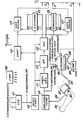
- FIGs. lA and 1B when joined in the fashion shown in Fig. lC, show apparatus adapted to perform a preferred process involving the principles of the present invention.
- Figs. lA and 1B when connected as shown in Fig. 1C, depict a hardware style system capable of practicing the best mode of the present invention, to wit, a method for automatically measuring blood pressure. It is to be understood, however, that the method may also be practiced in software or algorithmic fashion by means of appropriately programmed, commercially available processors. Hence, whether the means for practicing the methods defining the present invention are configured in one fashion or the other will largely depend upon the sophistication and predilection of the designer, the apparatus on hand, and sundry considerations of reliability, availability of components, price, and sophistication of the end user.
- an inflatable pressure cuff 102 is adapted to be worn on a suitable appendage of the subject, such as the arm 101 shown in phantom.
- a microphone 103 is mounted on the inner surface of the cuff, whereby the cuff is placed on an arm with the microphone 103 overlying or substantially adjacent a principal artery such as the brachial artery.
- the microphone is connected by means of wire 104 to conventional signal conditioning apparatus 119, such as amplifiers and filters.
- the cuff 102 is also connected by means of a hose 105 to a reservoir 106, which in turn is coupled by a hose 108 to a pump 107.
- the purpose of the reservoir 106 and hose 105, in conjunction with the cuff 102, is to provide a substantial gross volume of air which establishes pressure in the cuff 102, whereby muscle expansion and contraction of the arm 101 has substantially minimal effect upon the fluctuation of cuff pressure.
- the hose 105 preferably has a rather substantial diameter
- the reservoir 106 preferably has a volume substantially in excess of the volume of the cuff 102, whereby changes in cuff volume engender a rather insubstantial change in total volume (volume of cuff 102 plus volume of hose 105 plus volume of reservoir 106) and consequent minimal change in cuff pressure.
- the cuff 102, hose 105, and reservoir 106 share exchange of air and pressure freely, for practical purposes constituting but a single chamber (i.e. "volumetrically integral").
- the reservoir has attached thereto a control valve 111, a deflate valve 112, and a pressure transducer 113.
- the control valve 111 when opened as discussed hereinafter, accomplishes the decrementing of cuff pressure by controlled release of air from the reservoir 106.
- the deflate valve 112 which typically is substantially larger than the control valve 111, accom" plishes the final deflation of reservoir 106 and cuff 102 after both systolic and diastolic pressure have been measured.
- the transducer 113 senses the air pressure in the reservoir 106 (and correspondingly also in the cuff 102), and produces an electrical signal representative of that pressure.
- the transducer signal therefore, is the one which, at appropriate times, is identified as representing the systolic and diastolic pressures of the subject.
- a pump 107 which is energized by a start switch 109, establishes pressure within the reservoir 106, hose 105, and cuff 102 via connecting hose 108.
- the pump 107 senses the signal from transducer 113, in order properly to establish an initial pressure in the cuff 102.
- the pump 107 Upon actuation of the start switch 109, the pump 107 establishes within the cuff 102 a pressure which is in excess of systolic pressure, preferably a pressure which constricts the artery monitored by microphone 103 and prevents blood flow therethrough.
- the control valve 111 reduces the pressure in the cuff 102 in increments.
- a clock 100 is shown coupled generally to the apparatus, its purpose being to provide control and regulation of timing for all the apparatus.
- An electrocardiograph (ECG) 117 is shown schematically, with three electrodes, 114, 115, and 116 suitably located on the body of the subject, in conventional fashion, to produce an output signal representative of cardiac function.
- Such signal is known as the PQRST complex.
- the "R” aspect of the signal known as the "R-wave” is a signal impulse which denotes the depolarizing of the cardiac ventricles.
- Such pulse is preceded by the Q-wave, denoting the wave of atrial contraction arriving at the ventricles, and is terminated at the time of the S-wave.
- the so-called S-T interval denotes the electrical recovery time of the ventricles or the time intervals between the end of ventricular depolarization and beginning of repolarization.
- detection of the R-wave at 118 is utilized for purposes of "ECG gating", whereby representations of noise and spurious artifacts are obtained just before and/or just after the occurrence of the R-wave, and representations of signal plus noise and spurious signal are obtained a predetermined time thereafter (e.g. generally during the S-T and/or P-R intervals).
- ECG gating representations of noise and spurious artifacts are obtained just before and/or just after the occurrence of the R-wave, and representations of signal plus noise and spurious signal are obtained a predetermined time thereafter (e.g. generally during the S-T and/or P-R intervals).
- Each detected R-wave is coupled to a counter 124, to a sample and hold circuit 121, to an analog to digital converter 122, and to a multiplexer 123.
- the microphone signal is sampled at 121 via signal conditioning circuitry 119, and the samples are suitably converted to digital representations at converter 122.
- the digital representations of samples are coupled to a multiplexer 123, which for a time stores and then selectively distributes digital samples to either of two buffers 125 and 126, at the times, under control of the R-wave detector 118, during which a sample is to be utilized.
- a first plurality of samples (i.e. 16 in number for the embodiment of Figs. lA and 1B) is to be accumulated and stored in respective bins of the buffer 125, with the samples having a fixed time relationship to the R-wave, preferably just before and just after the R-wave at equal intervals during a one-tenth second period.
- the embodiment of Figs. lA and 1B also employs, for each R-wave, accumulation and storage of a second plurality of samples (32 in number in the embodiment of Figs.
- the multiplexer 123 has capacity for temporary storage of a plurality of samples (e.g. at least 8) whereby, upon detection of an R-wave, those 8 samples just before such detection are available for storage in the first eight bins of the buffer 125.
- the 8 samples immediately after the detected R-wave are so stored in buffer in the next 8 bins of buffer 125, and 32 next subsequent samples are distributed to and stored in respective bins of the buffer 126.
- this procedure is to be followed for a number of times (e.g. 4 to 10) at each increment of the cuff 102, depending on the heart rate of the subject.
- each bin of the buffer has correspondingly stored therein a plurality (e.g.
- each set of samples within a bin is a representation of signal or noise level, occurring on a recurrent basis at that particular cuff pressure level or increment.
- R-waves are so sampled, and correspondingly between 4 and 10 samples are so accumulated in each bin, because at a given level of exercise, and for a given time duration (i.e. related to the time duration at which a given pressure level is to be maintained at the cuff 102), each individual subject will sustain a different heart beat rate, and the numbers of separate samples in each bin of the buffer will be roughly in proportion to that heart rate.
- samples from the buffers 125 and 126 are conveyed to respective sum and average circuits, 128 and 127.
- the sum and average circuit 128 has the function of producing a first index, from the data stored in buffer 125, which is a representation of noise.
- the sum and average circuit 127 has the similar task of producing a second index which is representative of signal plus noise. Upon comparison of these two indices, there results a differential which corresponds to signal free of noise.
- a preferred method is as follows. First, the respective quantities stored in each bin of the buffers 125 and 126 are added to one another, yielding 16 separate sums from the buffer 125, and 32 separate sums from the buffer 126. Next, running averages are taken for each buffer 125 and 126. With respect to the data from the buffer 125, the sums from the first four bins are averaged, the sums from the second through fifth are averaged, the sums from the third through sixth are averaged, and the running average is so continued through the buffer 125.
- a similar running average is accumulated at circuit 127 upon data from the second buffer 126.
- a key one e.g. the largest
- combinations of ones e.g. the average
- the index so identified at th sum and average circuit 127, representing the aggregate o data assembled in the ST and/or P-R intervals, represents signal plus noise. Accordingly, the differential between the two indices represents, for that given cuff pressure level, a representation of signal.
- the respective indices from circuit 127 and 128 are coupled to a subtraction circuit 129, which determines the difference therebetween, coupling that difference both to a comparator 130 and to deflation control unit 132.
- comparator 130 evaluates the differential index from subtractor 129 with respect to a reference threshold established at 131, thereby to determine whether the differential index from subtraction circuit 129, is sufficiently large to be regarded as a Korotkoff sound. If the differential from subtraction circuit 129 is greater than the threshold level from 131, indicating presence of a Korotkoff sound, a logical 1, or output pulse, is produced by comparator 130; otherwise, a logical 0, or no pulse, is produced.
- the signal bits from comparator 131 are coupled via line 134 to a parallel storage unit 133 (e.g. a shift register), and for each such bit from the comparator (i.e. D 1 , D 1 , ... D N ), the cuff pressure then extant, as noted by the transducer 113, is also placed into the associated storage in parallel store 133, via input line 135, (i.e. pressure P 1 at which bit D 1 was evaluated pressure P 2 at which bit D 2 was evaluated, and so on).
- a parallel storage unit 133 e.g. a shift register
- the parallel store 133 maintains in storage a succession of cuff pressure increments (P 1 , P 2 ... P N ), and for each, an associated binary bit (D 1 , D 2 ...D N ) indicating whether the signal level at the appropriate time was sufficiently greater than the noise level to indicate presence of a Korotkoff sound.
- P 1 , P 2 ... P N cuff pressure increments
- D 1 , D 2 ...D N an associated binary bit
- the first logical 1 bit from comparator 130 tentatively indicates first occurrence of Korotkoff sound, and can be utilized to identify the pressure then extant in the cuff as systolic pressure.
- a preferable, higher security course of action is to identify systolic pressure as the former of the first two successive pressure levels in cuff 102 for which successive logical 1 bits are produced by comparator 130.
- a systolic latch 136 is adjusted to register systolic pressure at output display 138 as the first pressure P 1 of a P l -P 2 combination for which D 1 and D 2 are both logical ones.
- the first logical zero bit from comparator 130 after a succession of logical 1 bits, tentatively indicates cessation of occurrence of Korotkoff sounds, and such logical zero bit alone can be utilized to identify the pressure then extant in the cuff as diastolic pressure.
- a preferable, higher security course of action is to identify diastolic pressure as the former of two successive pressure levels in cuff 102, which follow a level having a logical 1 bit from comparator 130, and for which successive logical zer bits are produced by comparator 130.
- diastolic latch 130 is conditioned to couple to diastolic output display 139 the pressure P 2 of a P 1 - P 2 - P 3 combination for which D 1 is a logical 1 and D 2 and D 3 are both logical zeroes.
- An alternative approach to identification of diastolic pressure entails an adaptation of the Fig. 1B apparatus, for direct consideration of the differential indices from subtraction circuit 129. It is known that, just prior to cessation of Korotkoff sounds, there occurs a succession of Korotkoff sounds whose amplitudes rapidly decrease. I accordance with such alternative method for identifying diastolic pressure, then, differences between successive differential indices from subtraction circuit 129 are computed, and they in turn are compared with a stored reference threshold. When such index-to-index difference are greater than the stored threshold, the cessation of Korotkoff sounds is imminent, and diastolic pressure is deemed to occur.
- the differential index from subtraction circuit 129 i coupled not only to comparator 130, but also to deflation increment control 132.
- the deflation increment control unit performs two functions, first the ongoing regulating of the incremental step size, from cuff pressure level to cuff pressure level, and secondly, providing for larger "one-shot” stepwise decreases subsequent to identificationio of systolic pressure, but prior to identification of diastolic pressure.
- deflation increment control functions performed by deflation increment control are optional, and that the apparatus as heretofore described will provide adequate measurement of systolic and diastolic pressures whether the decrements between cuff pressure levels are regular or irregular.
- control valve 111 is energized to open for a time roughly proportional to the size of the differential inde from subtraction circuit 129.
- Simple operational amplifier circuitry may be adapted to perform this function, in accordance with the abilities of those of ordinary skill in the art.
- the deflation increment control 132 may be adapted, upon successful identification of the systolic pressure, to open control valve 111 and thereby to reduce pressure in the cuff 102 to the lower of:
- bits from comparator 130, as well as the transducer pressure 113, are available to deflation increment control 132.
- an enabling connection from the systolic latch 136 may be employed.
- An additional criterion, if available is to deflate control valve based either on the two foregoing criteria, or in any event within 25 mmHg. above the most recent previously measured diastolic pressure.
- an energizing signal is coupled from diastolic latch 137 to the deflation valve 112, thereby expeditiously to relieve pressure in the cuff 102.
- a mixer 140 receives, on an ongoing basis, the pressure signal from transducer 113, the ECG signal from 117, and the unsampled microphone signal from signal conditioning circuitry 119.
- these three analog signals are combined, such as by simple superposition, and the combination is printed such as on strip chart by recorder 141.
- This aggregate signal may be employed by the clinician as a hard copy of the signals whereby, employing graphical methods, systolic and diastolic pressures may roughly be computed, and checked against the pressures displayed at 138 and 139, if desired.
Landscapes
- Health & Medical Sciences (AREA)
- Life Sciences & Earth Sciences (AREA)
- Cardiology (AREA)
- Engineering & Computer Science (AREA)
- Public Health (AREA)
- Medical Informatics (AREA)
- Veterinary Medicine (AREA)
- Physics & Mathematics (AREA)
- General Health & Medical Sciences (AREA)
- Biophysics (AREA)
- Pathology (AREA)
- Biomedical Technology (AREA)
- Heart & Thoracic Surgery (AREA)
- Animal Behavior & Ethology (AREA)
- Molecular Biology (AREA)
- Surgery (AREA)
- Physiology (AREA)
- Vascular Medicine (AREA)
- Psychiatry (AREA)
- Computer Vision & Pattern Recognition (AREA)
- Signal Processing (AREA)
- Artificial Intelligence (AREA)
- Ophthalmology & Optometry (AREA)
- Measuring Pulse, Heart Rate, Blood Pressure Or Blood Flow (AREA)
Applications Claiming Priority (2)
| Application Number | Priority Date | Filing Date | Title |
|---|---|---|---|
| US9402079A | 1979-11-14 | 1979-11-14 | |
| US94020 | 1979-11-14 |
Publications (3)
| Publication Number | Publication Date |
|---|---|
| EP0029349A2 true EP0029349A2 (fr) | 1981-05-27 |
| EP0029349A3 EP0029349A3 (en) | 1982-03-31 |
| EP0029349B1 EP0029349B1 (fr) | 1985-06-05 |
Family
ID=22242303
Family Applications (1)
| Application Number | Title | Priority Date | Filing Date |
|---|---|---|---|
| EP80304068A Expired EP0029349B1 (fr) | 1979-11-14 | 1980-11-13 | Appareil de mesure automatique de la pression sanguine |
Country Status (4)
| Country | Link |
|---|---|
| EP (1) | EP0029349B1 (fr) |
| CA (1) | CA1163327A (fr) |
| DE (1) | DE3070743D1 (fr) |
| DK (1) | DK485680A (fr) |
Cited By (14)
| Publication number | Priority date | Publication date | Assignee | Title |
|---|---|---|---|---|
| FR2515503A1 (fr) * | 1981-11-05 | 1983-05-06 | Asulab Sa | Procede de mesure de la pression sanguine d'un sujet et sphygmomanometre mettant en oeuvre ce procede |
| WO1985000099A1 (fr) * | 1983-06-29 | 1985-01-17 | Sri International | Mesure de la pression sanguine avec detection d'informations relatives au son de korotkov et rejet des bruits parasites |
| EP0123313A3 (en) * | 1983-04-25 | 1987-01-07 | Nippon Colin Co., Ltd. | Apparatus for automatically measuring blood pressure |
| EP0252398A1 (fr) * | 1986-06-30 | 1988-01-13 | Spacelabs, Inc. | Appareil d'ambulance pour mesurer la pression sanguine |
| US4757824A (en) * | 1985-08-21 | 1988-07-19 | Kontron Holding A.G. | Method and apparatus for monitoring respiration |
| EP0207805A3 (en) * | 1985-07-05 | 1988-07-20 | Critikon, Inc. | Improved sphygmomanometric cuff pressurizing system improved sphygmomanometric cuff pressurizing system |
| EP0197302A3 (fr) * | 1985-03-11 | 1989-02-01 | TERUMO KABUSHIKI KAISHA trading as TERUMO CORPORATION | Procédé et appareil pour la mesure de la fonction circulatoire |
| EP0203181A4 (fr) * | 1984-11-27 | 1989-05-11 | Univ North Carolina | Procede et appareil portatif et automatique de controle de la pression sanguine. |
| EP0445809A3 (en) * | 1990-03-08 | 1992-07-29 | Mueller & Sebastiani Elektronik-Gmbh | Device for measuring blood pressure |
| EP0581313A1 (fr) * | 1992-07-30 | 1994-02-02 | Spacelabs Medical, Inc. | Procédé et dispositif destiné au rejet de signaux néfastes lors de la surveillance automatique de la pression sanguine |
| US5392781A (en) * | 1991-04-16 | 1995-02-28 | Cardiodyne, Incorporated | Blood pressure monitoring in noisy environments |
| US6258037B1 (en) | 1999-06-25 | 2001-07-10 | Cardiodyne Division Of Luxtec Corporation | Measuring blood pressure in noisy environments |
| WO2002034129A1 (fr) * | 2000-10-24 | 2002-05-02 | Optovent Ab | Methode et appareil d'epreuve d'effort de capacite |
| CN112450907A (zh) * | 2020-11-05 | 2021-03-09 | 珠海中科先进技术研究院有限公司 | 柯式音血压测量方法及装置 |
Families Citing this family (6)
| Publication number | Priority date | Publication date | Assignee | Title |
|---|---|---|---|---|
| US5052397A (en) * | 1985-07-05 | 1991-10-01 | Critikon, Inc. | Oscillometric blood pressure monitor employing non-uniform pressure decrementing steps |
| US5170795A (en) * | 1985-07-05 | 1992-12-15 | Critikon, Inc. | Oscillometric blood pressure monitor and method employing non-uniform pressure decrementing steps |
| US4754761A (en) * | 1985-07-05 | 1988-07-05 | Critikon, Inc. | Automated mean arterial blood pressure monitor with data enhancement |
| DE3533912A1 (de) * | 1985-09-23 | 1987-04-02 | Schmid Walter | Blutdruckmessgeraet |
| US5022403A (en) * | 1987-03-11 | 1991-06-11 | Cas Medical Systems, Inc. | Automatic blood pressure measuring device and method with cuff size determination |
| CN111657900B (zh) * | 2020-04-28 | 2021-08-17 | 四川大学 | 一种柯氏音时相分类识别方法及系统 |
Family Cites Families (4)
| Publication number | Priority date | Publication date | Assignee | Title |
|---|---|---|---|---|
| US3101082A (en) * | 1961-01-31 | 1963-08-20 | St Barnabas Hospital For Chron | Apparatus for measuring systolic and diastolic blood pressures |
| GB955011A (en) * | 1961-10-19 | 1964-04-08 | United Bristol Hospitals | Apparatus for recording blood pressure |
| US4116230A (en) * | 1976-09-10 | 1978-09-26 | Gorelick Donald E | Blood pressure cuff automatic deflation device |
| US4216779A (en) * | 1977-05-16 | 1980-08-12 | Del Mar Avionics | Blood pressure monitoring system |
-
1980
- 1980-11-12 CA CA000364432A patent/CA1163327A/fr not_active Expired
- 1980-11-13 DK DK485680A patent/DK485680A/da not_active Application Discontinuation
- 1980-11-13 DE DE8080304068T patent/DE3070743D1/de not_active Expired
- 1980-11-13 EP EP80304068A patent/EP0029349B1/fr not_active Expired
Cited By (16)
| Publication number | Priority date | Publication date | Assignee | Title |
|---|---|---|---|---|
| EP0079306A3 (fr) * | 1981-11-05 | 1984-11-07 | Asulab S.A. | Procédé de mesure de la pression sanguine d'un sujet |
| FR2515503A1 (fr) * | 1981-11-05 | 1983-05-06 | Asulab Sa | Procede de mesure de la pression sanguine d'un sujet et sphygmomanometre mettant en oeuvre ce procede |
| EP0123313A3 (en) * | 1983-04-25 | 1987-01-07 | Nippon Colin Co., Ltd. | Apparatus for automatically measuring blood pressure |
| WO1985000099A1 (fr) * | 1983-06-29 | 1985-01-17 | Sri International | Mesure de la pression sanguine avec detection d'informations relatives au son de korotkov et rejet des bruits parasites |
| EP0203181A4 (fr) * | 1984-11-27 | 1989-05-11 | Univ North Carolina | Procede et appareil portatif et automatique de controle de la pression sanguine. |
| EP0197302A3 (fr) * | 1985-03-11 | 1989-02-01 | TERUMO KABUSHIKI KAISHA trading as TERUMO CORPORATION | Procédé et appareil pour la mesure de la fonction circulatoire |
| EP0207805A3 (en) * | 1985-07-05 | 1988-07-20 | Critikon, Inc. | Improved sphygmomanometric cuff pressurizing system improved sphygmomanometric cuff pressurizing system |
| US4757824A (en) * | 1985-08-21 | 1988-07-19 | Kontron Holding A.G. | Method and apparatus for monitoring respiration |
| EP0252398A1 (fr) * | 1986-06-30 | 1988-01-13 | Spacelabs, Inc. | Appareil d'ambulance pour mesurer la pression sanguine |
| EP0445809A3 (en) * | 1990-03-08 | 1992-07-29 | Mueller & Sebastiani Elektronik-Gmbh | Device for measuring blood pressure |
| US5392781A (en) * | 1991-04-16 | 1995-02-28 | Cardiodyne, Incorporated | Blood pressure monitoring in noisy environments |
| EP0581313A1 (fr) * | 1992-07-30 | 1994-02-02 | Spacelabs Medical, Inc. | Procédé et dispositif destiné au rejet de signaux néfastes lors de la surveillance automatique de la pression sanguine |
| US5337750A (en) * | 1992-07-30 | 1994-08-16 | Spacelabs Medical, Inc. | Automatic blood pressure monitor employing artifact rejection method and apparatus |
| US6258037B1 (en) | 1999-06-25 | 2001-07-10 | Cardiodyne Division Of Luxtec Corporation | Measuring blood pressure in noisy environments |
| WO2002034129A1 (fr) * | 2000-10-24 | 2002-05-02 | Optovent Ab | Methode et appareil d'epreuve d'effort de capacite |
| CN112450907A (zh) * | 2020-11-05 | 2021-03-09 | 珠海中科先进技术研究院有限公司 | 柯式音血压测量方法及装置 |
Also Published As
| Publication number | Publication date |
|---|---|
| EP0029349A3 (en) | 1982-03-31 |
| DK485680A (da) | 1981-05-15 |
| CA1163327A (fr) | 1984-03-06 |
| EP0029349B1 (fr) | 1985-06-05 |
| DE3070743D1 (en) | 1985-07-11 |
Similar Documents
| Publication | Publication Date | Title |
|---|---|---|
| EP0029349B1 (fr) | Appareil de mesure automatique de la pression sanguine | |
| US4408614A (en) | Blood pressure measurement with Korotkov sound artifact information detection and rejection | |
| US4889132A (en) | Portable automated blood pressure monitoring apparatus and method | |
| US4677984A (en) | Calibrated arterial pressure measurement device | |
| US5680867A (en) | Electronic blood pressure measurment device | |
| US20080091115A1 (en) | Non-Invasive Measurement of Second Heart Sound Components | |
| EP0651970A1 (fr) | Méthode et appareil pour évaluer la performance cardiovasculaire | |
| US3762397A (en) | Method and apparatus for the detection and recordation of high frequency sound in the cardiovascular system | |
| US4974597A (en) | Apparatus for identifying artifact in automatic blood pressure measurements | |
| US20050004477A1 (en) | Method and apparatus for measuring blood pressure using relaxed matching criteria | |
| JP2001504362A (ja) | 加圧帯を使用しない非破壊式血圧測定装置 | |
| EP0698370B1 (fr) | Appareil pour la surveillance de la pression sanguine | |
| JPWO1994022363A1 (ja) | 電子血圧測定装置 | |
| CN101138492A (zh) | 利用SpO2体积描记信号减少NIBP确定时间的方法和系统 | |
| US4649929A (en) | Method and apparatus for diagnosis of coronary artery disease | |
| US8282567B2 (en) | Method and system for determination of pulse rate | |
| EP0203181B1 (fr) | Procede et appareil portatif et automatique de controle de la pression sanguine | |
| US20060224070A1 (en) | System and method for non-invasive cardiovascular assessment from supra-systolic signals obtained with a wideband external pulse transducer in a blood pressure cuff | |
| US4819654A (en) | Method and apparatus for diagnosis of coronary artery disease | |
| US5772600A (en) | Coherent pattern identification in non-stationary periodic data and blood pressure measurement using same | |
| CN100457025C (zh) | 用于改善t波交替的测量的系统 | |
| EP0150176B1 (fr) | Mesure de la pression sanguine avec detection d'informations relatives au son de korotkov et rejet des bruits parasites | |
| WO1985000279A1 (fr) | Procede et appareil pour diagnostiquer une affection de l'artere coronaire | |
| CA1181523A (fr) | Mesure de la pression sanguine au moyen de donnees sonores | |
| CN120203544A (zh) | 血压预测方法、装置及电子设备 |
Legal Events
| Date | Code | Title | Description |
|---|---|---|---|
| PUAI | Public reference made under article 153(3) epc to a published international application that has entered the european phase |
Free format text: ORIGINAL CODE: 0009012 |
|
| AK | Designated contracting states |
Designated state(s): BE CH DE FR GB IT NL SE |
|
| PUAL | Search report despatched |
Free format text: ORIGINAL CODE: 0009013 |
|
| AK | Designated contracting states |
Designated state(s): BE CH DE FR GB IT NL SE |
|
| 17P | Request for examination filed |
Effective date: 19820902 |
|
| GRAA | (expected) grant |
Free format text: ORIGINAL CODE: 0009210 |
|
| AK | Designated contracting states |
Designated state(s): BE CH DE FR GB IT LI NL SE |
|
| PG25 | Lapsed in a contracting state [announced via postgrant information from national office to epo] |
Ref country code: SE Free format text: THE PATENT HAS BEEN ANNULLED BY A DECISION OF A NATIONAL AUTHORITY Effective date: 19850605 Ref country code: NL Effective date: 19850605 Ref country code: LI Effective date: 19850605 Ref country code: IT Free format text: LAPSE BECAUSE OF FAILURE TO SUBMIT A TRANSLATION OF THE DESCRIPTION OR TO PAY THE FEE WITHIN THE PRESCRIBED TIME-LIMIT;WARNING: LAPSES OF ITALIAN PATENTS WITH EFFECTIVE DATE BEFORE 2007 MAY HAVE OCCURRED AT ANY TIME BEFORE 2007. THE CORRECT EFFECTIVE DATE MAY BE DIFFERENT FROM THE ONE RECORDED. Effective date: 19850605 Ref country code: CH Effective date: 19850605 Ref country code: BE Effective date: 19850605 |
|
| REF | Corresponds to: |
Ref document number: 3070743 Country of ref document: DE Date of ref document: 19850711 |
|
| ET | Fr: translation filed | ||
| REG | Reference to a national code |
Ref country code: CH Ref legal event code: PL |
|
| NLV1 | Nl: lapsed or annulled due to failure to fulfill the requirements of art. 29p and 29m of the patents act | ||
| PLBE | No opposition filed within time limit |
Free format text: ORIGINAL CODE: 0009261 |
|
| STAA | Information on the status of an ep patent application or granted ep patent |
Free format text: STATUS: NO OPPOSITION FILED WITHIN TIME LIMIT |
|
| 26N | No opposition filed | ||
| GBPC | Gb: european patent ceased through non-payment of renewal fee | ||
| PG25 | Lapsed in a contracting state [announced via postgrant information from national office to epo] |
Ref country code: FR Free format text: LAPSE BECAUSE OF NON-PAYMENT OF DUE FEES Effective date: 19870731 |
|
| PG25 | Lapsed in a contracting state [announced via postgrant information from national office to epo] |
Ref country code: DE Effective date: 19870801 |
|
| REG | Reference to a national code |
Ref country code: FR Ref legal event code: ST |
|
| PG25 | Lapsed in a contracting state [announced via postgrant information from national office to epo] |
Ref country code: GB Effective date: 19881118 |