EP0029482A1 - Interrupteur à gaz comprimé - Google Patents
Interrupteur à gaz comprimé Download PDFInfo
- Publication number
- EP0029482A1 EP0029482A1 EP80104260A EP80104260A EP0029482A1 EP 0029482 A1 EP0029482 A1 EP 0029482A1 EP 80104260 A EP80104260 A EP 80104260A EP 80104260 A EP80104260 A EP 80104260A EP 0029482 A1 EP0029482 A1 EP 0029482A1
- Authority
- EP
- European Patent Office
- Prior art keywords
- cylinder
- piston
- switch
- push rod
- stroke
- Prior art date
- Legal status (The legal status is an assumption and is not a legal conclusion. Google has not performed a legal analysis and makes no representation as to the accuracy of the status listed.)
- Granted
Links
- 238000007664 blowing Methods 0.000 claims description 17
- 239000011324 bead Substances 0.000 claims description 3
- 230000002093 peripheral effect Effects 0.000 description 7
- 230000008878 coupling Effects 0.000 description 4
- 238000010168 coupling process Methods 0.000 description 4
- 238000005859 coupling reaction Methods 0.000 description 4
- 230000006835 compression Effects 0.000 description 3
- 238000007906 compression Methods 0.000 description 3
- 230000001133 acceleration Effects 0.000 description 1
- 238000010791 quenching Methods 0.000 description 1
- 230000000171 quenching effect Effects 0.000 description 1
- 230000001603 reducing effect Effects 0.000 description 1
- 238000005096 rolling process Methods 0.000 description 1
Images

Classifications
-
- H—ELECTRICITY
- H01—ELECTRIC ELEMENTS
- H01H—ELECTRIC SWITCHES; RELAYS; SELECTORS; EMERGENCY PROTECTIVE DEVICES
- H01H33/00—High-tension or heavy-current switches with arc-extinguishing or arc-preventing means
- H01H33/70—Switches with separate means for directing, obtaining, or increasing flow of arc-extinguishing fluid
- H01H33/88—Switches with separate means for directing, obtaining, or increasing flow of arc-extinguishing fluid the flow of arc-extinguishing fluid being produced or increased by movement of pistons or other pressure-producing parts
- H01H33/90—Switches with separate means for directing, obtaining, or increasing flow of arc-extinguishing fluid the flow of arc-extinguishing fluid being produced or increased by movement of pistons or other pressure-producing parts this movement being effected by or in conjunction with the contact-operating mechanism
- H01H33/91—Switches with separate means for directing, obtaining, or increasing flow of arc-extinguishing fluid the flow of arc-extinguishing fluid being produced or increased by movement of pistons or other pressure-producing parts this movement being effected by or in conjunction with the contact-operating mechanism the arc-extinguishing fluid being air or gas
Definitions
- the invention relates to a gas pressure switch with a movable contact piece fastened to the end of a push rod, which can be brought into and out of engagement with a stationary contact piece, and with a blowing nozzle which gives the free end of the movable contact piece and is fastened to the push rod.
- a gas pressure switch with a movable contact piece fastened to the end of a push rod, which can be brought into and out of engagement with a stationary contact piece, and with a blowing nozzle which gives the free end of the movable contact piece and is fastened to the push rod.
- a pump chamber containing extinguishing gas and enclosed by a cylinder, which can be pressurized in the course of a switch-off stroke, the cylinder being displaceably guided on a stationary supported piston.
- Such switches are known and, thanks to their simple design (stationary supported pistons), have also proven themselves, especially since the cylinder can also serve as a movable nominal current contact, which can serve in and out of engagement with a corresponding, stationary counter contact.
- the cylinder itself is fastened to the push rod via a flange or via the blowing nozzle, ie with the movable one Contact piece connected, which means that considerable masses must be accelerated, especially at the beginning of the switch-off stroke. This in turn requires a very powerful switch drive.
- the proposed gas pressure switch according to the invention is characterized in that the blowing nozzle is designed as the bottom of a second piston opposite the first piston, which can be displaced relative to the cylinder in this between two end positions, means being provided around the cylinder during a switch-off stroke in the same direction as the movable contact piece, but to move a smaller distance than this.
- the means for moving the cylinder in the same direction as the movable contact piece during a switch-off stroke, but for moving a smaller distance can be designed in the simplest embodiment as a drag connection between the blow nozzle designed as a piston and the cylinder itself.
- This towing connection can have two stops which are arranged at a distance from one another in the cylinder and which fix the end positions of the blowing nozzle with respect to the cylinder, which can be biased in the direction of the switch-off stroke by means of a spring.
- This spring which is tightened more during the switch-on stroke, also serves as an energy accumulator that supports the drive.
- the cylinder can also be coupled via a gearbox (lever, friction wheel or gearwheel gearbox) to the push rod which moves the movable contact piece and the blowing nozzle, which gearbox has a reducing effect in the direction of the cylinder.
- a gearbox lever, friction wheel or gearwheel gearbox
- the movement of the cylinder with respect to that of the push rod remains well defined in every phase of the switch-off stroke.
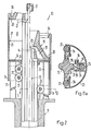
- the pressure gas switch 10 shown is shown in the left half of FIGS. 1-3 in the on position, in the right half in the off position, functionally corresponding components being identified by the same reference numerals.
- An electrically conductive support 11 carries a tubular insulating housing 12, only partially shown, in which the essential components of the switch are arranged and which contains an extinguishing gas under pressure, for example SF 6 .
- a pin-shaped contact piece 14 attached to the free end of a push rod 13 is in and out of engagement with a tubular, stationary by means of a drive, not shown, which moves the push rod 13 either in the direction of arrow 15 (switch-off stroke) or arrow 16 (switch-on stroke) arranged contact piece 17 can be brought.
- a blowing nozzle 18 is fastened by means not shown, which surrounds the movable contact piece 14 with its nozzle space 19 and is in front of it with its narrowest point 20.
- the inlets 21 of the blowing nozzle 18 are directly connected to a pump chamber 22.
- the circumference of the pump chamber 22 is delimited by a cylinder 23, which in turn is slidably guided on a pump piston 24.
- the pump piston 24 is firmly supported on the support 11 by means of several (at least two) columns 25.
- the blowing nozzle 18 is also slidably mounted in the cylinder 23 and thus also acts as a piston.
- a first stop 26 and a second stop 27 is formed on the inside of the cylinder 23 at the upper end thereof. These stops are intended to cooperate with the peripheral flange 28 of the blowing nozzle 18 and thus determine the extent of the relative movement of the blowing nozzle 18 in the cylinder 23. These stops 26, 27, together with the peripheral flange 28, form an effective towing connection between the push rod 13 and the cylinder 23.
- the cylinder 23 is biased in the direction of the switch-off stroke, and the springs 21 act as a force accumulator, which is coupled to the push rod 13 via the cylinder 23, the stop 26, the peripheral flange 28 and supports the drive at least at the beginning of the switch-off movement and for acceleration of the movable contact piece 14 contributes.
- the movable contact piece moves during the switch-off stroke 14 and with it the blowing nozzle 18 away from the fixed contact piece 17.
- the cylinder 23 also moves away from the fixed contact piece, but only until the stop 27 comes to rest on the stationary piston 24. Then the cylinder 23 stops, the peripheral flange 28 detaches from the stop 26, and now the blowing nozzle, which now acts as a piston, displaces the extinguishing gas from the remaining pump chamber until the position shown in FIG. 1 on the right is reached.
- the cylinder 23 has traveled a shorter distance than the switching stroke by the distance indicated by the dimensional arrow 31.
- the cylinder 23 initially stops and is only raised when the peripheral flange 28 of the blowing nozzle 18 strikes the stop 26, the compression springs 29 then being tensioned again.
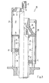
- FIG. 1 While, as mentioned, in FIG. 1 the cylinder 23 is coupled to the push rod 13 via a towing connection, a gear is provided for this coupling in FIGS. 2 and 3, namely a force-locking in FIG. 2 and in FIG. 3 a positive gear.
- bulges 33 are formed on the circumferentially longitudinally extending sides with an outwardly convex cross section, which are each arranged opposite one of the columns 25 supporting the piston 24.
- the number of beads 33 (four are shown, but it could just as well be two or three) are attached to the inside of the cylinder 23 in its lower region pairs of inwardly extending bearing plates 34, the bearing plates 34 of a pair each encompassing a column 25 with play.
- Two pairs of smooth bevel gears 35, 36 are rotatably mounted on a pin 37 on each pair of bearing plates.
- the two bevel gears 35, 36 of a pair are arranged facing each other with their smaller diameters.
- the bevel gear 35 is firmly seated on the pin 37 rotatably mounted in the bearing plates 34, while the bevel gear 36 is freely rotatable on the pin 37.
- the pin 37 extending beyond the bevel gear 36 is under the action of a compression spring 38, so that the bevel gears 35, 36 are resiliently biased toward one another.
- the bevel gears 35, 36 roll on the one hand on the assigned, stationary column 25, on the other hand on the bead 33 formed on the push rod 13 and thus also act as rolling contacts between the push rod 13 and the relevant column 25, that is, between the movable one Contact piece 14 and the support 11.
- the stop 27 can also be provided in this embodiment — as indicated by dashed lines — via which the cylinder 23 is then by means of the peripheral flange 28 and under Ueberwin Extension of the frictional connection between the columns 25 and the push rod 13 on the one hand and the bevel gears 35, 36 on the other hand is pressed into its lowest position at the end of the switch-off stroke.
- a toothed rack 39 is attached to the stationary columns 25 and a toothed rack 40 is also attached to the sides of the push rod 13 opposite the columns 25.
- bearing brackets 41 are fastened to the inside of the cylinder, in each of which a gear 42 meshing both with the rack 39 and with the rack 40 is freely rotatable.
- the mode of operation of this embodiment largely corresponds to that of the embodiment according to FIG. 2 with the difference already mentioned that the coupling between the push rod 13 and the cylinder 23 is slip-free.
- springs can also be provided in the embodiments of FIGS. 2 and 3, which load the cylinder 23 in the direction of the switch-off stroke, and thus also serve as an energy store supporting the switch drive.
Landscapes
- Circuit Breakers (AREA)
- Driving Mechanisms And Operating Circuits Of Arc-Extinguishing High-Tension Switches (AREA)
- Percussion Or Vibration Massage (AREA)
- Glass Compositions (AREA)
- Vehicle Body Suspensions (AREA)
Priority Applications (1)
| Application Number | Priority Date | Filing Date | Title |
|---|---|---|---|
| AT80104260T ATE2764T1 (de) | 1979-11-22 | 1980-07-19 | Druckgasschalter. |
Applications Claiming Priority (2)
| Application Number | Priority Date | Filing Date | Title |
|---|---|---|---|
| CH1041379A CH642481A5 (de) | 1979-11-22 | 1979-11-22 | Druckgasschalter. |
| CH10413/79 | 1979-11-22 |
Publications (2)
| Publication Number | Publication Date |
|---|---|
| EP0029482A1 true EP0029482A1 (fr) | 1981-06-03 |
| EP0029482B1 EP0029482B1 (fr) | 1983-03-09 |
Family
ID=4362958
Family Applications (1)
| Application Number | Title | Priority Date | Filing Date |
|---|---|---|---|
| EP80104260A Expired EP0029482B1 (fr) | 1979-11-22 | 1980-07-19 | Interrupteur à gaz comprimé |
Country Status (6)
| Country | Link |
|---|---|
| US (1) | US4379958A (fr) |
| EP (1) | EP0029482B1 (fr) |
| JP (1) | JPS5686421A (fr) |
| AT (1) | ATE2764T1 (fr) |
| CH (1) | CH642481A5 (fr) |
| DE (1) | DE3062280D1 (fr) |
Cited By (1)
| Publication number | Priority date | Publication date | Assignee | Title |
|---|---|---|---|---|
| EP0999569A3 (fr) * | 1998-11-02 | 2002-09-18 | ABB Schweiz AG | Interrupteur de puissance |
Families Citing this family (2)
| Publication number | Priority date | Publication date | Assignee | Title |
|---|---|---|---|---|
| CH658745A5 (de) * | 1982-10-25 | 1986-11-28 | Sprecher & Schuh Ag | Druckgasschalter. |
| DE3322597A1 (de) * | 1983-05-31 | 1984-12-06 | BBC Aktiengesellschaft Brown, Boveri & Cie., Baden, Aargau | Druckgasschalter |
Citations (5)
| Publication number | Priority date | Publication date | Assignee | Title |
|---|---|---|---|---|
| DE1216407B (de) * | 1960-05-27 | 1966-05-12 | Calor Emag Elektrizitaets Ag | Elektrischer Schalter mit selbsterzeugter Loeschmittel-, insbesondere Druckgasstroemung |
| CH517371A (de) * | 1970-06-24 | 1971-12-31 | Bbc Brown Boveri & Cie | Elektrischer Kompressionsschalter |
| FR2226740A1 (fr) * | 1973-04-17 | 1974-11-15 | Hitachi Ltd | |
| DE2336684A1 (de) * | 1973-07-19 | 1975-01-30 | Bbc Brown Boveri & Cie | Druckgasschalter |
| FR2346841A1 (fr) * | 1976-03-30 | 1977-10-28 | Merlin Gerin | Structure d'un interrupteur electrique d'autosoufflage |
Family Cites Families (2)
| Publication number | Priority date | Publication date | Assignee | Title |
|---|---|---|---|---|
| CH524886A (de) * | 1970-12-01 | 1972-06-30 | Bbc Brown Boveri & Cie | Elektrischer Kompressionsschalter |
| JPS5913816B2 (ja) * | 1975-05-29 | 1984-04-02 | 三菱電機株式会社 | 開閉器 |
-
1979
- 1979-11-22 CH CH1041379A patent/CH642481A5/de not_active IP Right Cessation
-
1980
- 1980-07-19 DE DE8080104260T patent/DE3062280D1/de not_active Expired
- 1980-07-19 EP EP80104260A patent/EP0029482B1/fr not_active Expired
- 1980-07-19 AT AT80104260T patent/ATE2764T1/de not_active IP Right Cessation
- 1980-09-02 US US06/183,430 patent/US4379958A/en not_active Expired - Lifetime
- 1980-11-17 JP JP16181380A patent/JPS5686421A/ja active Granted
Patent Citations (5)
| Publication number | Priority date | Publication date | Assignee | Title |
|---|---|---|---|---|
| DE1216407B (de) * | 1960-05-27 | 1966-05-12 | Calor Emag Elektrizitaets Ag | Elektrischer Schalter mit selbsterzeugter Loeschmittel-, insbesondere Druckgasstroemung |
| CH517371A (de) * | 1970-06-24 | 1971-12-31 | Bbc Brown Boveri & Cie | Elektrischer Kompressionsschalter |
| FR2226740A1 (fr) * | 1973-04-17 | 1974-11-15 | Hitachi Ltd | |
| DE2336684A1 (de) * | 1973-07-19 | 1975-01-30 | Bbc Brown Boveri & Cie | Druckgasschalter |
| FR2346841A1 (fr) * | 1976-03-30 | 1977-10-28 | Merlin Gerin | Structure d'un interrupteur electrique d'autosoufflage |
Cited By (1)
| Publication number | Priority date | Publication date | Assignee | Title |
|---|---|---|---|---|
| EP0999569A3 (fr) * | 1998-11-02 | 2002-09-18 | ABB Schweiz AG | Interrupteur de puissance |
Also Published As
| Publication number | Publication date |
|---|---|
| CH642481A5 (de) | 1984-04-13 |
| JPS5686421A (en) | 1981-07-14 |
| US4379958A (en) | 1983-04-12 |
| EP0029482B1 (fr) | 1983-03-09 |
| ATE2764T1 (de) | 1983-03-15 |
| JPH0154813B2 (fr) | 1989-11-21 |
| DE3062280D1 (en) | 1983-04-14 |
Similar Documents
| Publication | Publication Date | Title |
|---|---|---|
| DE10016334A1 (de) | Anordnung zur Steuerung der Bewegung einer heckseitigen Luftleitvorrichtung an Kraftfahrzeugen | |
| EP0039822A1 (fr) | Dispositif de commande pour un fuseau d'avance | |
| DE3915522A1 (de) | Antriebsvorrichtung fuer eine vakuumschaltroehre mit einer kontaktfeder | |
| DE2411744C3 (de) | Presse zum Pressverbinden eines Kabels oder isolierten Drahtes mit einem Kabelschuh | |
| EP1101538A2 (fr) | Appareil d'extrusion électrique pour cartouches | |
| EP0029482B1 (fr) | Interrupteur à gaz comprimé | |
| DE2043744C3 (de) | Elektrischer Kompressionsschalter | |
| DE3825100C2 (de) | Vorrichtung zum Öffnen des Abstichloches eines Schachtofens | |
| DE2011488C3 (de) | Vorrichtung zum Greifen und abschnittsweisen Verschieben von Werkstücken | |
| DE2450973C3 (de) | Vorrichtung zur Verstellung des Stößelhubes bei Doppelständerpressen mit zwei nebeneinander liegenden Exzenterwellen | |
| DE10003325C2 (de) | Vorschubeinrichtung für den Oberschlitten einer Presse | |
| DE2603536C3 (de) | Antriebsvorrichtung für elektrische Schaltgeräte | |
| DE2847355C2 (de) | Schmiedewalzwerk | |
| DE10231609A1 (de) | Getriebeschaltung | |
| DE2650493C2 (de) | Autopneumatischer Druckgasschalter | |
| DE913664C (de) | Antrieb fuer bewegliche Schaltstuecke, insbesondere Schaltstifte od. dgl. bei elektrischen Hochspannungsschaltgeraeten | |
| DE2935439C2 (de) | Antriebseinrichtung für Werkzeugschlitten von Draht- und Bandbiegeautomaten | |
| DE1615777C3 (fr) | ||
| AT394468B (de) | Druckgasschalter | |
| DE2653077C2 (de) | Schalter | |
| DE933370C (de) | Antrieb fuer Spindelpressen | |
| DE2344352C3 (de) | Schalter mit einem zwischen dem bewegbaren Schaltkontakt und einem Steuerorgan angeordneten Kupplungsgetriebe | |
| DE1452771C3 (de) | Abstreifvorrichtung an einer Presse zum Fließpressen von Werkstücken, wie Dosenkörper, Hülsen usw | |
| DE2736392A1 (de) | Autopneumatischer druckgasschalter | |
| DE2707594B1 (de) | Druckgasschalter |
Legal Events
| Date | Code | Title | Description |
|---|---|---|---|
| PUAI | Public reference made under article 153(3) epc to a published international application that has entered the european phase |
Free format text: ORIGINAL CODE: 0009012 |
|
| AK | Designated contracting states |
Designated state(s): AT BE DE FR GB NL |
|
| 17P | Request for examination filed |
Effective date: 19810423 |
|
| GRAA | (expected) grant |
Free format text: ORIGINAL CODE: 0009210 |
|
| AK | Designated contracting states |
Designated state(s): AT BE DE FR GB NL |
|
| REF | Corresponds to: |
Ref document number: 2764 Country of ref document: AT Date of ref document: 19830315 Kind code of ref document: T |
|
| REF | Corresponds to: |
Ref document number: 3062280 Country of ref document: DE Date of ref document: 19830414 |
|
| ET | Fr: translation filed | ||
| PGFP | Annual fee paid to national office [announced via postgrant information from national office to epo] |
Ref country code: FR Payment date: 19890616 Year of fee payment: 10 |
|
| PGFP | Annual fee paid to national office [announced via postgrant information from national office to epo] |
Ref country code: DE Payment date: 19890619 Year of fee payment: 10 Ref country code: BE Payment date: 19890619 Year of fee payment: 10 |
|
| PGFP | Annual fee paid to national office [announced via postgrant information from national office to epo] |
Ref country code: AT Payment date: 19890626 Year of fee payment: 10 |
|
| PGFP | Annual fee paid to national office [announced via postgrant information from national office to epo] |
Ref country code: GB Payment date: 19890630 Year of fee payment: 10 |
|
| PGFP | Annual fee paid to national office [announced via postgrant information from national office to epo] |
Ref country code: NL Payment date: 19890731 Year of fee payment: 10 |
|
| PG25 | Lapsed in a contracting state [announced via postgrant information from national office to epo] |
Ref country code: GB Effective date: 19900719 Ref country code: AT Effective date: 19900719 |
|
| PG25 | Lapsed in a contracting state [announced via postgrant information from national office to epo] |
Ref country code: BE Effective date: 19900731 |
|
| BERE | Be: lapsed |
Owner name: SPRECHER & SCHUH A.G. Effective date: 19900731 |
|
| PG25 | Lapsed in a contracting state [announced via postgrant information from national office to epo] |
Ref country code: NL Effective date: 19910201 |
|
| NLV4 | Nl: lapsed or anulled due to non-payment of the annual fee | ||
| GBPC | Gb: european patent ceased through non-payment of renewal fee | ||
| PG25 | Lapsed in a contracting state [announced via postgrant information from national office to epo] |
Ref country code: FR Effective date: 19910329 |
|
| PG25 | Lapsed in a contracting state [announced via postgrant information from national office to epo] |
Ref country code: DE Effective date: 19910403 |
|
| REG | Reference to a national code |
Ref country code: FR Ref legal event code: ST |
|
| PLBE | No opposition filed within time limit |
Free format text: ORIGINAL CODE: 0009261 |
|
| STAA | Information on the status of an ep patent application or granted ep patent |
Free format text: STATUS: NO OPPOSITION FILED WITHIN TIME LIMIT |