EP0029511A1 - Procédé et dispositif pour la coulée en coquille de métal fondu, en particulier d'un alliage léger - Google Patents
Procédé et dispositif pour la coulée en coquille de métal fondu, en particulier d'un alliage léger Download PDFInfo
- Publication number
- EP0029511A1 EP0029511A1 EP80106557A EP80106557A EP0029511A1 EP 0029511 A1 EP0029511 A1 EP 0029511A1 EP 80106557 A EP80106557 A EP 80106557A EP 80106557 A EP80106557 A EP 80106557A EP 0029511 A1 EP0029511 A1 EP 0029511A1
- Authority
- EP
- European Patent Office
- Prior art keywords
- casting
- die
- piston
- molten metal
- melt
- Prior art date
- Legal status (The legal status is an assumption and is not a legal conclusion. Google has not performed a legal analysis and makes no representation as to the accuracy of the status listed.)
- Withdrawn
Links
- 229910052751 metal Inorganic materials 0.000 title claims abstract description 44
- 239000002184 metal Substances 0.000 title claims abstract description 44
- 238000004512 die casting Methods 0.000 title claims abstract description 23
- 229910001234 light alloy Inorganic materials 0.000 title claims abstract description 13
- 238000000034 method Methods 0.000 title claims description 16
- 238000005266 casting Methods 0.000 claims abstract description 102
- 239000000155 melt Substances 0.000 claims abstract description 33
- 150000002739 metals Chemical class 0.000 claims abstract description 4
- 239000011261 inert gas Substances 0.000 claims description 22
- 238000004891 communication Methods 0.000 claims description 11
- 238000007711 solidification Methods 0.000 claims description 8
- 230000008023 solidification Effects 0.000 claims description 8
- 230000009471 action Effects 0.000 claims description 6
- 238000005119 centrifugation Methods 0.000 claims description 6
- 230000005484 gravity Effects 0.000 claims description 4
- 230000002000 scavenging effect Effects 0.000 claims description 3
- 229910001338 liquidmetal Inorganic materials 0.000 claims description 2
- 230000006835 compression Effects 0.000 claims 1
- 238000007906 compression Methods 0.000 claims 1
- 239000000463 material Substances 0.000 description 11
- 230000003647 oxidation Effects 0.000 description 7
- 238000007254 oxidation reaction Methods 0.000 description 7
- 239000007789 gas Substances 0.000 description 5
- 238000004519 manufacturing process Methods 0.000 description 5
- 230000008901 benefit Effects 0.000 description 4
- 239000002893 slag Substances 0.000 description 4
- XAGFODPZIPBFFR-UHFFFAOYSA-N aluminium Chemical compound [Al] XAGFODPZIPBFFR-UHFFFAOYSA-N 0.000 description 3
- 239000012535 impurity Substances 0.000 description 3
- 230000005499 meniscus Effects 0.000 description 3
- 230000007935 neutral effect Effects 0.000 description 3
- 239000002699 waste material Substances 0.000 description 3
- 229910000838 Al alloy Inorganic materials 0.000 description 2
- IJGRMHOSHXDMSA-UHFFFAOYSA-N Atomic nitrogen Chemical compound N#N IJGRMHOSHXDMSA-UHFFFAOYSA-N 0.000 description 2
- 230000001133 acceleration Effects 0.000 description 2
- 230000015572 biosynthetic process Effects 0.000 description 2
- 238000005056 compaction Methods 0.000 description 2
- 238000009827 uniform distribution Methods 0.000 description 2
- 229910052782 aluminium Inorganic materials 0.000 description 1
- 238000013459 approach Methods 0.000 description 1
- 238000009749 continuous casting Methods 0.000 description 1
- 238000001816 cooling Methods 0.000 description 1
- 238000009826 distribution Methods 0.000 description 1
- 230000009977 dual effect Effects 0.000 description 1
- 230000000694 effects Effects 0.000 description 1
- 239000012530 fluid Substances 0.000 description 1
- 239000006260 foam Substances 0.000 description 1
- 230000008676 import Effects 0.000 description 1
- 230000006872 improvement Effects 0.000 description 1
- 238000002347 injection Methods 0.000 description 1
- 239000007924 injection Substances 0.000 description 1
- 239000007788 liquid Substances 0.000 description 1
- 238000012423 maintenance Methods 0.000 description 1
- 238000002844 melting Methods 0.000 description 1
- 230000008018 melting Effects 0.000 description 1
- 238000012986 modification Methods 0.000 description 1
- 230000004048 modification Effects 0.000 description 1
- 229910052757 nitrogen Inorganic materials 0.000 description 1
- 230000000149 penetrating effect Effects 0.000 description 1
- 230000009467 reduction Effects 0.000 description 1
- 238000011282 treatment Methods 0.000 description 1
Images

Classifications
-
- B—PERFORMING OPERATIONS; TRANSPORTING
- B22—CASTING; POWDER METALLURGY
- B22D—CASTING OF METALS; CASTING OF OTHER SUBSTANCES BY THE SAME PROCESSES OR DEVICES
- B22D39/00—Equipment for supplying molten metal in rations
- B22D39/02—Equipment for supplying molten metal in rations having means for controlling the amount of molten metal by volume
-
- B—PERFORMING OPERATIONS; TRANSPORTING
- B22—CASTING; POWDER METALLURGY
- B22D—CASTING OF METALS; CASTING OF OTHER SUBSTANCES BY THE SAME PROCESSES OR DEVICES
- B22D18/00—Pressure casting; Vacuum casting
- B22D18/04—Low pressure casting, i.e. making use of pressures up to a few bars to fill the mould
-
- B—PERFORMING OPERATIONS; TRANSPORTING
- B22—CASTING; POWDER METALLURGY
- B22D—CASTING OF METALS; CASTING OF OTHER SUBSTANCES BY THE SAME PROCESSES OR DEVICES
- B22D21/00—Casting non-ferrous metals or metallic compounds so far as their metallurgical properties are of importance for the casting procedure; Selection of compositions therefor
- B22D21/002—Castings of light metals
- B22D21/007—Castings of light metals with low melting point, e.g. Al 659 degrees C, Mg 650 degrees C
-
- B—PERFORMING OPERATIONS; TRANSPORTING
- B22—CASTING; POWDER METALLURGY
- B22D—CASTING OF METALS; CASTING OF OTHER SUBSTANCES BY THE SAME PROCESSES OR DEVICES
- B22D27/00—Treating the metal in the mould while it is molten or ductile ; Pressure or vacuum casting
- B22D27/09—Treating the metal in the mould while it is molten or ductile ; Pressure or vacuum casting by using pressure
- B22D27/11—Treating the metal in the mould while it is molten or ductile ; Pressure or vacuum casting by using pressure making use of mechanical pressing devices
Definitions
- This invention relates to a die-casting device for melt metal, in particular melt light alloy.
- the very high pressure light alloy casting technique wherein the aluminum or light alloy melt is injected at a very high pressure into a casting die. That technique has the advantage of a high casting rate and good compacting of the molten aluminum or light alloy throughout the casting die inside, such that even the remotest areas from the injection nozzles are reached therein.
- a casting technique of that type involves a high percentage of reject, because a successful casting is allowed to rely in-practice on- uncontrollable random factors during the production stage, and above all on account of the disuniform compactness achieved.
- Another drawback is that the casting apparatus and die must be constructed and dimensioned to withstand the high pressure levels involved, .of. at least a hundred atmospheres, which results in a substantially high plant cost.
- That apparatus has the disadvantage of requiring a preliminary metering of the melt to be introduced into the casting die, which involves the necessity of opening the reservoir to the external environment, in order to pour the molten metal therein, with attendant unavoidable oxidation of part of the molten metal.
- melt reservoir is formed in the chiller die itself beside the casting cavity, such that it can be uncovered as the die or casting cavity is opened to withdraw the casting.
- the amount of molten metal which is poured into the reservoir is preset externally to the apparatus, such as to have a volume of molten metal which substantially equals the volume required to fill the casting die, plus an allowance for the riser and the meniscus which forms at the reservoir bottom after the casting step.
- such devices afford the advantage of providing castings in which the gradual introduction of the melt into the casting die allows a good' compaction of the material, owing to the pressure exerted on the reservoir during the introduction of the molten metal into the casting die, as well as to the gradual introduction of. the molten metal into the die, which avoids the stressing and ill-treatments which are typical of the very high pressure method.
- German Patent No. 2720352 to Zeppellini discloses a device which enables a continuous cycle production of castings. It comprises in essence a casting die, which may obviously have any desired shape, having at the top a molten metal filling hole whereto a large ladle can be secured in.sealed relationship which has at the bottom an outlet nozzle, located at the casting die filling hole, which nozzle is closed tightly by a movable shutter.
- This approach affords the possibility of scavenging the die with an inert gas to be admitted through a conduit coaxial to the shutter and controlled by a closure plate or cap provided at the bottom end with a stem which extends coaxially inside the shutter.
- the shutter element is movable to put the ladle in communication with the casting die, such as to enable the molten metal to be poured into the die.
- an air or compressed gas intake conduit which exerts a low pressure of the order of a few atmosphere units, which facilitates the introduction of the melt into the casting die and causes it to reach the remotest corners of the die or chill.
- the die can be rotated such that a more complete and uniform distribution of the melt is achieved by centrifugal action.
- the ladle is removed and, after refilling at the holding furnace, it is applied to a successive casting die to go through the same steps described hereinabove.
- the apparatus just described also provides for a moderate pressure action which facilitates the introduction of the melt into the die, by compensating for the difference in height between the pouring hole and upper portion of the chill. Also, the apparatus just described allows the size of the risers to be minimized, because the shutter closes the casting apparatus bottom tightly upon completion of the metal pouring into the die, thus preventing material waste.
- the apparatus in addition to a number of drawbacks of a practical nature, has the disadvantage of a low output rate because it requires that the metal has completely solidified within the die, before the ladle can be removed for application to a successive die, as dictated by the fact that it is the very ladle which provides the pressure during the solidification stage as the die is closed.
- Another problem is of a constructional nature, in that the seal between the ladle and casting die is in practice critically affected, in view of the fact that it should allow for the rotation of the die while the ladle is held stationary.
- This invention sets out to provide a die -casting device for metal, in particular melt light alloy, which in addition to providing an absolutely faultless casting is also capable of a very high hourly output, such as cannot be found in similar conventional devices.
- the casting device according to this invention allows the' metering of an accurate amount of melt in an inert gas environment, thus completely eliminating the presence of slag and impurities from the resulting casting.
- the casting device of this invention allows the ladle to be removed immediately after the melt has been poured and prior to its beginning to solidify in the die, thus affording a drastic reduction of the production time and making the device specially suitable for use with a continuous casting machine.
- the die - casting device according to this invention is highly reliable in operation and safe to use, while being mechanically simple and requiring a greatly reduced amount of maintenance.
- a die-casting device for melt metals for melt metals, in particular melt light alloys, characterized in that it comprises a body rigidly associated at the top thereof with one of the chill forming elements defining the casting die, said body having an internal cavity in communication, through a passage port, with a filling compartment adapted for being closed at the top in sealed relationship by a molten metal feeder removably attachable to the mouth of said filling compartment, a piston being provided sealingly movable in said cavity adapted "to operate as a metering device for the melt to be poured into the casting die and to- sealingly close said passage port upon completion of the melt pouring step, a shutter element being also provided to control the passage orifice between said cavity and said casting die.
- the die - casting device is generally indicated at 1 and comprises a body 2 located at the top of one of the elements composing a casting die generally indicated at 3 and no further described because known per se, the die being shaped to match the shape of the castings to be produced; for example purposes, the drawings show a die intended for casting a wheel.
- Said body 2 is rigid with at least one of the elements making up the casting die 3 and is associated therewith through an intervening seal 4.
- a cavity 5 which has an orifice 20 at the bottom for communication with the casting die defined by the chill 3.
- Said cavity 5 communicates, at its bottom portion and through a passage port 6, with a filling compartment 7 which extends substantially upwards and terminates with a top mouth 8.
- Said filling compartment 7 can be closed at the top tightly by means of a molten metal feeder, e.g. comprising a ladle 9 which removably engages in sealed relationship with the cited top or upper mouth 8.
- a molten metal feeder e.g. comprising a ladle 9 which removably engages in sealed relationship with the cited top or upper mouth 8.
- the ladle 9 is provided, at the area of engagement with the mouth 8, with a delivery outlet or mouth 10 controlled by means of a shutter stem 11.
- a piston 15 driven by a double-acting cylinder 16 arranged to slide in a chamber 17 formed in the upper portion of the body 11.
- a delivery conduit 18 and return conduit 19 which follow the movements of the cylinder 16, and accordingly of the piston 15 rigid therewith.
- the orifice 20 which communicates the cavity 5 with the casting die is controlled by a shutter 21 which penetrates in sealed relationship coaxially to the piston 15 and chamber 17 and is driven, for its vertical direction movement, by an auxiliary cylinder 22 arranged to slide in sealed relationship in an auxiliary chamber 23 provided above the chamber 17 and being fed above and below said auxiliary cylinder 23 through a first conduit 25 and second conduit 26.
- the shutter 21 additionally to functioning as an orifice closing element, can also act as a punch for compacting the central portion of the cast melt during the centrifugation thereof, as will be explained hereinafter.
- a pusher piston 27 which,by penetrating the cast melt,is effective to compact the metal still in its molten state to compensate for any shrinkage during the final stage of the melt solidification.
- an inert gas feeding conduit 30 which opens to an annular interstice or gap 31 defined within the piston 15 and in communication with the cavity 5 through small channels 32 which opens to the bottom or lower face of the piston 15.
- Said inert gas feeding conduit is in communication with an inert gas delivery valving unit, over the line 33, which unit is enabled, as will be explained hereinafter, to admit low pressure inert gas, i.e. gas at a pressure of the order of a few atmospheres, or possibly an inert gas at a high pressure, of the order of several dozens atmospheres.
- low pressure inert gas i.e. gas at a pressure of the order of a few atmospheres, or possibly an inert gas at a high pressure, of the order of several dozens atmospheres.
- the casting process is carried out as follows.
- the chill 3 is assumed to be empty and ready for casting; the-shutter element 21 is in its raised position, that is such as to allow free communication of the cavity 5 with the casting die; the piston 15 is positioned such that the volume defined by the cavity 5 and filling compartment 7 is equal to, or slightly larger than the volume of molten metal to be introduced into the casting die; the ladle 9 is applied to the top mouth 8 such as to seal off the filling compartment 7; and the stem shutter 11 holds the delivery mouth 10 of the ladle 9 closed.
- an inert gas such as nitrogen and the like, is admitted into the cavity 5, filling compartment 7, and casting die 3, such as to practically scavenge those areas whereto the melt will flow.
- the shutter 21 is lowered to close the orifice 20 communicating to the casting die 3 tightly.
- the stem shutter 11 of the ladle 9 is opened to pour the melt out of the ladle; the melt will fill the cavity 5 and filling compartment 7, practically flowing by gravity into the metering chamber, formed by the cavity 5,which has a variable volume in accordance with the position of the piston 15,and by the filling compartment, which has obviously a constant volume capacity.
- the stem shutter 11 is operated to close the delivery mouth of the ladle 9, whereafter the orifice 20 is opened by raising the shutter 21.
- the fluid melt will fill by gravity almost every part of the casting die defined by the chill, to leave the filling compartment 7 and a part of the cavity 5 left empty by the metal.
- the piston 15 begins to move downwards and, through the conduit 30, low pressure neutral gas is introduced which, as mentioned hereinabove, facilitates an optimal filling of the die and enables the height difference between the pouring area and the highest areas of the casting die to be compensated; this avoids the formation of very high risers.
- the piston 15 will cover, in its downward travel, the passage port 6, thus completely breaking the communication between the cavity 5 and compartment 7.
- the centrifugation has the very important .function of feeding the remote or outward portions of the casting being produced,whereat solidification occurs in advance owing to the smaller thickness dimensions, to compensate for the shrinkage of the material by adding material which is in practice absorbed by the central portion where the metal is still in its liquid state.
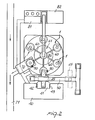
- the machine shown in Figure 2 comprises a casting unit which includes a dual body melting furnace 40 feeding a holding furnace 41 through doors or gates 42 and 43 which are opened alternately in synchonization with their related furnace bodies.
- a cross carriage device 45 which will not be described in detail herein because known per se, picks up the molten metal from the holding furnace 40 and introduces it, through the ladle 9 described hereinabove, into the body 2..
- the arm 50 of the cross carriage 45 enables the ladle 9 to be unloaded outside of the working area for its periodical replacement.
- the last step of introducing high pressure neutral gas may be carried out while the device 1 is being moved to the successive station.
- the device 1 is practically carried by the extensions 60 of a carousel element 61 which is rotated intermittently at regular time intervals to bring sequentially the various devices 1 to the loading station.
- the device 1 is brought, by successive rotational movements, to the unloading station 70, whereat the pressure applied to the melt is released and the now solidified casting is withdrawn from the chill and started along the casting cooling conveyor 71.
- the carousel rotation evidently occurs in steps, the rate of advance being a function of the time required by the number of the casts relatively to the solidification of each single cast.
- a manifold 80 connects the carousel 60 to a control unit 81 and electro-hydraulic control 82.
- the casting process may include a final centrifugation step, thereby the chills 3, as described hereinabove, instead of being held stationary, would be made rotatable by means of motors, generally hydraulic ones, provided below the carousel and so designed that, during the passage from the casting station to the following station, a controlled acceleration of the chill occurs which is then maintained as far as the last but one station. From the latter to the-unloading station, a deceleration takes place, until a full stop condition is reached at a preset position as determined by clutches 90 having the function of positioning the device 1 such that the mouth 8 of the filling compartment 7 is located at the path followed by the ladle 9.
- the invention achieves its objects, and in particular that a continuous and substantially automated casting process has been provided which has a high rate of casting output, thanks to the combination of a carousel carrying either stationary or rotary chills with a device which enables, in sequential steps, casting by gravity, at a low and high pressure, throughout the path travelled by a chill on the carousel up to the automatic casting unloading station, while other casts may follow one another alternately, which take place prior to the complete solidification of the metal which has been poured into the preceding chills.
- the piston 15 one is enabled, first of all, to effect an accurate metering of the melt directly at the pouring time, while the piston will ensure a tight sealed closure of the communication with the outside environment, thus permitting the ladle to be removed prior to the melt within the die beginning to solidify.
- piston 15 can be utilized to further increase the pressure applied during the final stage of the casting process, when very high pressure inert gas is introduced.
- this device affords the possibility of providing an extremely versatile and functional plant, capable of meeting the requirements of any users; in fact, the inventive device can be used singly and operated manually, or be incorporated in a semiautomatic or fully automatic cycle carousel type of casting machine with an hourly output which can be adjusted to suit the individual requirements of its users.
- the materials employed if compatible with the specific intended application, and the dimensions and contingent shapes may be any ones, depending on individual requirements.
Landscapes
- Engineering & Computer Science (AREA)
- Mechanical Engineering (AREA)
- Molds, Cores, And Manufacturing Methods Thereof (AREA)
Applications Claiming Priority (2)
| Application Number | Priority Date | Filing Date | Title |
|---|---|---|---|
| IT27249/79A IT1124969B (it) | 1979-11-13 | 1979-11-13 | Dispositivo di colata in conchiglia di metallo fuso in genere e di lega leggera in particolare |
| IT2724979 | 1979-11-13 |
Publications (1)
| Publication Number | Publication Date |
|---|---|
| EP0029511A1 true EP0029511A1 (fr) | 1981-06-03 |
Family
ID=11221275
Family Applications (1)
| Application Number | Title | Priority Date | Filing Date |
|---|---|---|---|
| EP80106557A Withdrawn EP0029511A1 (fr) | 1979-11-13 | 1980-10-25 | Procédé et dispositif pour la coulée en coquille de métal fondu, en particulier d'un alliage léger |
Country Status (5)
| Country | Link |
|---|---|
| EP (1) | EP0029511A1 (fr) |
| JP (1) | JPS5684163A (fr) |
| AR (1) | AR223250A1 (fr) |
| BR (1) | BR8007192A (fr) |
| IT (1) | IT1124969B (fr) |
Cited By (14)
| Publication number | Priority date | Publication date | Assignee | Title |
|---|---|---|---|---|
| FR2504424A1 (fr) * | 1981-04-22 | 1982-10-29 | Amil Sa | Procede et dispositif perfectionnes de coulee par gravite avec pression additionnelle par verin |
| FR2529492A1 (fr) * | 1982-06-30 | 1984-01-06 | Logvinov Anatoly | Moule pour la production de moulages par refoulage |
| EP0318655A3 (en) * | 1987-10-05 | 1989-10-25 | Tva Holding S.P.A. | Process for casting molten metal, in particular aluminium alloys and magnesium alloys, and device for its execution |
| EP0273586A3 (en) * | 1986-12-01 | 1990-04-25 | Ube Industries, Ltd. | Vertical injection apparatus vertical injection apparatus |
| EP0599768A1 (fr) * | 1992-11-20 | 1994-06-01 | Agustin Arana Erana | Dispositif d'alimentation de métal sans basse pression d'un moule et sable borgne, moule et installation de coules correspondants |
| ES2110884A1 (es) * | 1992-11-20 | 1998-02-16 | Erana Agustin Arana | Segundo certificado de adicion por mejoras introducidas en la p.i. 9202341, por maquina para llenado de moldes de arena con metales no ferreos mediante tecnica de baja presion. |
| EP0845321A1 (fr) * | 1996-11-29 | 1998-06-03 | Showa Aluminum Corporation | Procédé de brasage d'éléments d'aluminium coulés sous pression |
| EP1695777A1 (fr) * | 2005-02-17 | 2006-08-30 | Senator Technology GmbH | Dispositif et procédé de coulée |
| CN102935499A (zh) * | 2011-08-16 | 2013-02-20 | 苏州三基铸造装备股份有限公司 | 一种为给汤机配套的汤杯 |
| CN108620557A (zh) * | 2018-05-25 | 2018-10-09 | 东莞市镁正隆工业熔炉设备有限公司 | 一种合金压铸给料精密计量设备及其工作方法 |
| CN114799132A (zh) * | 2021-01-20 | 2022-07-29 | 通用汽车环球科技运作有限责任公司 | 铸造在线加压室 |
| CN115889738A (zh) * | 2023-02-08 | 2023-04-04 | 保定奥琦圣新型金属材料制造有限公司 | 一种合金生产用定量浇铸装置 |
| CN116475389A (zh) * | 2023-04-26 | 2023-07-25 | 江西威能汽车零部件有限公司 | 一种刹车双缸钳体加工辅助工装 |
| CN116727639A (zh) * | 2023-06-20 | 2023-09-12 | 顺达模具科技有限公司 | 一种汽车离合器挤压铸造成形模具 |
Families Citing this family (4)
| Publication number | Priority date | Publication date | Assignee | Title |
|---|---|---|---|---|
| CN103878349A (zh) * | 2014-03-22 | 2014-06-25 | 中信戴卡宁波轮毂制造有限公司 | 一种铸造方法及装置 |
| CN106735083B (zh) * | 2016-12-28 | 2018-05-11 | 滨州渤海活塞有限公司 | 一种高气压铸造头部预制件增强活塞模具 |
| CN109702172A (zh) * | 2019-01-28 | 2019-05-03 | 广东鸿泰南通精机科技有限公司 | 一种具有真空提前导入功能的压装模具结构 |
| CN112059148B (zh) * | 2020-10-29 | 2024-07-19 | 禹州市恒利来新材料有限公司 | 一种铸铝件用发热保温冒口套 |
Citations (8)
| Publication number | Priority date | Publication date | Assignee | Title |
|---|---|---|---|---|
| GB122133A (en) * | 1918-07-19 | 1919-01-16 | Wallace Cranston Fairweather | Apparatus for Making Metal Castings. |
| FR575542A (fr) * | 1923-03-22 | 1924-08-01 | Procédé et appareil pour la coulée sous pression | |
| CH230300A (de) * | 1941-11-19 | 1943-12-31 | Silumin Ges Mbh | Giessverfahren. |
| DE745944C (de) * | 1939-06-14 | 1944-05-30 | Willi Strecker | Giessvorrichtung fuer Leichtmetall |
| DE1160259B (de) * | 1959-07-24 | 1963-12-27 | Vaw Ver Aluminium Werke Ag | Durch Polieren und anschliessende Schutzoxydation mit dauerhaftem Hochglanz versehene Gussteile aus Aluminium oder Aluminiumlegierungen |
| US3128912A (en) * | 1964-04-14 | Metering device for molten metal | ||
| US3188703A (en) * | 1962-08-08 | 1965-06-15 | Kelsey Hayes Co | Apparatus for low pressure permanent mold casting |
| DE2720352A1 (de) * | 1976-05-10 | 1977-11-17 | Dino Marco Mario Zeppellini | Giesspfanne |
-
1979
- 1979-11-13 IT IT27249/79A patent/IT1124969B/it active
-
1980
- 1980-10-25 EP EP80106557A patent/EP0029511A1/fr not_active Withdrawn
- 1980-10-30 AR AR283071A patent/AR223250A1/es active
- 1980-11-06 BR BR8007192A patent/BR8007192A/pt unknown
- 1980-11-13 JP JP15890880A patent/JPS5684163A/ja active Pending
Patent Citations (8)
| Publication number | Priority date | Publication date | Assignee | Title |
|---|---|---|---|---|
| US3128912A (en) * | 1964-04-14 | Metering device for molten metal | ||
| GB122133A (en) * | 1918-07-19 | 1919-01-16 | Wallace Cranston Fairweather | Apparatus for Making Metal Castings. |
| FR575542A (fr) * | 1923-03-22 | 1924-08-01 | Procédé et appareil pour la coulée sous pression | |
| DE745944C (de) * | 1939-06-14 | 1944-05-30 | Willi Strecker | Giessvorrichtung fuer Leichtmetall |
| CH230300A (de) * | 1941-11-19 | 1943-12-31 | Silumin Ges Mbh | Giessverfahren. |
| DE1160259B (de) * | 1959-07-24 | 1963-12-27 | Vaw Ver Aluminium Werke Ag | Durch Polieren und anschliessende Schutzoxydation mit dauerhaftem Hochglanz versehene Gussteile aus Aluminium oder Aluminiumlegierungen |
| US3188703A (en) * | 1962-08-08 | 1965-06-15 | Kelsey Hayes Co | Apparatus for low pressure permanent mold casting |
| DE2720352A1 (de) * | 1976-05-10 | 1977-11-17 | Dino Marco Mario Zeppellini | Giesspfanne |
Cited By (17)
| Publication number | Priority date | Publication date | Assignee | Title |
|---|---|---|---|---|
| FR2504424A1 (fr) * | 1981-04-22 | 1982-10-29 | Amil Sa | Procede et dispositif perfectionnes de coulee par gravite avec pression additionnelle par verin |
| FR2529492A1 (fr) * | 1982-06-30 | 1984-01-06 | Logvinov Anatoly | Moule pour la production de moulages par refoulage |
| EP0273586A3 (en) * | 1986-12-01 | 1990-04-25 | Ube Industries, Ltd. | Vertical injection apparatus vertical injection apparatus |
| EP0318655A3 (en) * | 1987-10-05 | 1989-10-25 | Tva Holding S.P.A. | Process for casting molten metal, in particular aluminium alloys and magnesium alloys, and device for its execution |
| EP0599768A1 (fr) * | 1992-11-20 | 1994-06-01 | Agustin Arana Erana | Dispositif d'alimentation de métal sans basse pression d'un moule et sable borgne, moule et installation de coules correspondants |
| ES2110884A1 (es) * | 1992-11-20 | 1998-02-16 | Erana Agustin Arana | Segundo certificado de adicion por mejoras introducidas en la p.i. 9202341, por maquina para llenado de moldes de arena con metales no ferreos mediante tecnica de baja presion. |
| EP0845321A1 (fr) * | 1996-11-29 | 1998-06-03 | Showa Aluminum Corporation | Procédé de brasage d'éléments d'aluminium coulés sous pression |
| US5934546A (en) * | 1996-11-29 | 1999-08-10 | Showa Aluminum Corporation | Process for brazing die-cast aluminum material |
| EP1695777A1 (fr) * | 2005-02-17 | 2006-08-30 | Senator Technology GmbH | Dispositif et procédé de coulée |
| CN102935499A (zh) * | 2011-08-16 | 2013-02-20 | 苏州三基铸造装备股份有限公司 | 一种为给汤机配套的汤杯 |
| CN108620557A (zh) * | 2018-05-25 | 2018-10-09 | 东莞市镁正隆工业熔炉设备有限公司 | 一种合金压铸给料精密计量设备及其工作方法 |
| CN114799132A (zh) * | 2021-01-20 | 2022-07-29 | 通用汽车环球科技运作有限责任公司 | 铸造在线加压室 |
| CN114799132B (zh) * | 2021-01-20 | 2024-03-15 | 通用汽车环球科技运作有限责任公司 | 铸造在线加压室 |
| CN115889738A (zh) * | 2023-02-08 | 2023-04-04 | 保定奥琦圣新型金属材料制造有限公司 | 一种合金生产用定量浇铸装置 |
| CN115889738B (zh) * | 2023-02-08 | 2023-05-26 | 保定奥琦圣新型金属材料制造有限公司 | 一种合金生产用定量浇铸装置 |
| CN116475389A (zh) * | 2023-04-26 | 2023-07-25 | 江西威能汽车零部件有限公司 | 一种刹车双缸钳体加工辅助工装 |
| CN116727639A (zh) * | 2023-06-20 | 2023-09-12 | 顺达模具科技有限公司 | 一种汽车离合器挤压铸造成形模具 |
Also Published As
| Publication number | Publication date |
|---|---|
| BR8007192A (pt) | 1981-05-19 |
| IT7927249A0 (it) | 1979-11-13 |
| JPS5684163A (en) | 1981-07-09 |
| AR223250A1 (es) | 1981-07-31 |
| IT1124969B (it) | 1986-05-14 |
Similar Documents
| Publication | Publication Date | Title |
|---|---|---|
| EP0029511A1 (fr) | Procédé et dispositif pour la coulée en coquille de métal fondu, en particulier d'un alliage léger | |
| DE19613668C1 (de) | Gießanlage und Verfahren zur Herstellung von Gußstücken | |
| US4519436A (en) | Method for injecting molten metal in vertical diecasting machine | |
| KR100456764B1 (ko) | 회전식 주조 방법 및 장치 | |
| US2181157A (en) | Method and apparatus for pressure casting | |
| US20070215308A1 (en) | Vertical Casting Apparatus and Vertical Casting Method | |
| GB2045659A (en) | Charging die casting machines | |
| US5758711A (en) | Molding apparatus for minimizing shrinkage and voids | |
| US5121406A (en) | Induction melting furnace | |
| US4550763A (en) | Method and machine for pressure diecasting | |
| JP2013035008A (ja) | ダイカスト鋳造装置及びダイカスト鋳造方法 | |
| EP0177257B1 (fr) | Machine de coulée | |
| US4958675A (en) | Method for casting metal alloys with low melting temperatures | |
| US3410332A (en) | Method and apparatus for casting metals in a controlled atmosphere | |
| US7854251B2 (en) | Method and device for casting molten metal | |
| JP2007253168A (ja) | 竪型鋳造装置及び竪型鋳造方法 | |
| US4060122A (en) | Low-pressure die casting machine | |
| EP0095513B1 (fr) | Procédé de coulée sous pression de type vertical | |
| US2068875A (en) | Pressure casting machine | |
| US1759269A (en) | Fbebebick c | |
| JP2008264796A (ja) | 竪型鋳造装置及び竪型鋳造方法 | |
| US5090470A (en) | Apparatus for casting metal alloys with low melting temperatures | |
| US5031686A (en) | Method for casting metal alloys with low melting temperatures | |
| CN216370124U (zh) | 一种蝶阀加工用阀片成型装置 | |
| CA1218827A (fr) | Chaine de production de pieces coulees, surtout pour la coulee a contre-pression |
Legal Events
| Date | Code | Title | Description |
|---|---|---|---|
| PUAI | Public reference made under article 153(3) epc to a published international application that has entered the european phase |
Free format text: ORIGINAL CODE: 0009012 |
|
| AK | Designated contracting states |
Designated state(s): DE FR GB |
|
| STAA | Information on the status of an ep patent application or granted ep patent |
Free format text: STATUS: THE APPLICATION IS DEEMED TO BE WITHDRAWN |
|
| 18D | Application deemed to be withdrawn |
Effective date: 19820507 |
|
| RIN1 | Information on inventor provided before grant (corrected) |
Inventor name: FRULLA, CLAUDIO |