EP0029516B1 - Trommel für Waschmaschine - Google Patents
Trommel für Waschmaschine Download PDFInfo
- Publication number
- EP0029516B1 EP0029516B1 EP19800106629 EP80106629A EP0029516B1 EP 0029516 B1 EP0029516 B1 EP 0029516B1 EP 19800106629 EP19800106629 EP 19800106629 EP 80106629 A EP80106629 A EP 80106629A EP 0029516 B1 EP0029516 B1 EP 0029516B1
- Authority
- EP
- European Patent Office
- Prior art keywords
- drum
- side wall
- end parts
- parts
- apertures
- Prior art date
- Legal status (The legal status is an assumption and is not a legal conclusion. Google has not performed a legal analysis and makes no representation as to the accuracy of the status listed.)
- Expired
Links
- 230000001154 acute effect Effects 0.000 claims description 4
- 238000005406 washing Methods 0.000 description 14
- XLYOFNOQVPJJNP-UHFFFAOYSA-N water Substances O XLYOFNOQVPJJNP-UHFFFAOYSA-N 0.000 description 7
- 238000003466 welding Methods 0.000 description 5
- 238000001035 drying Methods 0.000 description 3
- 239000000463 material Substances 0.000 description 3
- 230000003014 reinforcing effect Effects 0.000 description 3
- 238000010276 construction Methods 0.000 description 2
- 238000010981 drying operation Methods 0.000 description 2
- 238000000926 separation method Methods 0.000 description 2
- 238000009987 spinning Methods 0.000 description 2
- 229910001220 stainless steel Inorganic materials 0.000 description 2
- 239000010935 stainless steel Substances 0.000 description 2
- 238000005299 abrasion Methods 0.000 description 1
- 230000004323 axial length Effects 0.000 description 1
- 230000000254 damaging effect Effects 0.000 description 1
- 230000001627 detrimental effect Effects 0.000 description 1
Images


Classifications
-
- D—TEXTILES; PAPER
- D06—TREATMENT OF TEXTILES OR THE LIKE; LAUNDERING; FLEXIBLE MATERIALS NOT OTHERWISE PROVIDED FOR
- D06F—LAUNDERING, DRYING, IRONING, PRESSING OR FOLDING TEXTILE ARTICLES
- D06F37/00—Details specific to washing machines covered by groups D06F21/00 - D06F25/00
- D06F37/02—Rotary receptacles, e.g. drums
- D06F37/04—Rotary receptacles, e.g. drums adapted for rotation or oscillation about a horizontal or inclined axis
Definitions
- the present invention relates to a laundry machine such as a washing machine, spin dryer, or tumble dryer, or any machine capable of carrying out any combination of the functions of the above mentioned machines.
- the invention is specifically concerned with a drum in which the laundry is to be placed during washing and/or drying operations.
- the best known type of drum in use in laundry machines typically comprises two cup- shaped parts, one at each end joined at the centre to form a drum, one of which parts has a large central aperture in one end thereof through which the laundry may be placed in and removed from the drum, the other part being provided with an axle or other bearing means by means of which the drum may be supported for rotation at a generally horizontal axis, the cylindrical side wall formed by the connecting parts having therein a large number of apertures usually in the form of circular holes to enable water to pass through the wall.
- the drum as aforedescribed When the laundry machine is a washing machine, the drum as aforedescribed will be placed in a substantially water-tight container and mounted for rotation within said container, the container being partially filled with water and emptied, either automatically or manually, during a washing cycle.
- the container In a normal automatic washing cycle the container can be filled and emptied several times to provide more than one washing operation and usually several rinsing operations.
- the type of drum described above has been in use for many years, however, there are problems with such drums.
- the apertures in the side wall of the drum even though they may be formed with rounded edge surfaces to avoid presentation of sharp edges to the laundry, are still detrimental to the laundry being washed or dried since damage can be caused by the tendency of the laundry to be pressed into the apertures.
- Machines have also been (FR-A-2,140,036) proposed in which a drum comprising a cylindrical perforated side wall part has been connected to end parts by way of radially projecting flanges on the side wall and end parts, the latter including portions of arcuate section presenting interior concave faces adjacent to the connections with the side wall part.
- This construction however would not promote good longitudinal distribution and moreover would suffer from the damaging effect of forcing the articles into the holes of the perforated side wall part.
- a drum in or for a laundry machine comprising end parts connected to opposite ends of an imperforate side wall part divergent internally from a position in the mid region of its length towards each of its ends, the connection in each case being through the intermediary of a flange on one of the parts projecting outwardly in a direction transverse to the interior surface of this part and through the intermediary of a spaced opposing face on the other of the parts, providing a plurality of circumferentially spaced apertures between the end parts and the side wall part, one only of the end parts being provided with mounting means for rotation of the drum about its axis, and the other of the end parts having a central aperture for access to the inside of the drum, characterized in that the end parts have rim portions of arcuate section presenting concave faces inwardly of the drum which are arranged to be in smooth continuation of the interior surface of the side wall part by providing outwardly projecting mutually opposing and connected flanges and on both the side wall and the end wall parts
- the flanges of the end parts are provided with the depression and lands, the flanges on the side wall being left substantially planar.
- such securement may be provided for by welding for example spot welding the mutual abutting contacting parts of the flanges.
- the innermost surface of the drum is as smooth as possible thereby greatly reducing the amount of damage to the clothes being washed or centrifugally dried in the drum, and furthermore presenting easily accessible contact sur- facts by means of which the end parts may be secured firmly to the side wall member of the drum, thereby making the assembly of the drum an operation which can be carried out with simple spot welding apparatus.
- the resultant construction may be easily inspected to ensure that the drum has been properly assembled.
- the arcuate rim portions of the end parts make a large contribution towards the strength of the drum and by providing the contact areas between the end parts and the side wall member at the radially outermost point of the drum, i.e. at positions of maximum diameter, it ensures that the contact surfaces between the end parts and the side wall member are at a position of maximum area and also at a position subjected to a smaller force.
- the drum of the present invention assists greatly in overcoming the problems aforementioned concerned with washing drums, the internal surface of the side wall member being generally imperforate will be as smooth as possible to minimise wear on the laundry during a washing or drying operation. Furthermore, the divergent side wall member contributes towards better distribution of clothes in the drum. The positioning of the apertures ensures there is minimum contact between the clothes and the apertures themselves in addition to providing a very convenient and strong assembly of the drum as a whole.
- the drum is of a diabolo shape but may be of generally arcuate form provided the position of minimum diameter is approximately mid-way between its ends.
- the mid-region of the side wall may be of substantially cylindrical configuration over a certain axial length of the drum, the two end regions of the side wall being divergent with. respect to the rotational axis towards the ends of the drum.
- the angle of divergence relative to the central axis of the drum is such that it is large enough to aid separation of individual items of laundry being washed or dried in a drum to prevent "balling" of several items together and generally assists separation of the laundry to improve the washing and drying thereof. Furthermore, the angle of divergence is not too large that would cause "bunching", at each end region, of the items of laundry being washed or dried.
- the acute angle between the central axis of the drum and such divergent section of the side wall should be greater than 2 1/2° and less than 10°.
- the drum of the present invention may be mounted for rotation about a horizontal or vertical axis or any angle therebetween but is primarily intended for a laundry machine in which the drum is rotated or oscillated about a substantially horizontal axis.
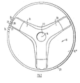
- a laundry machine drum has a first end part generally indicated at 10, a second end part generally indicated at 11, the second end part 11 having a central aperture 12 through which laundry may be put in or taken out of the drum in use of the laundry machine.
- the opening 12 is closed during use of the machine by a door which co-operates and closes an capitad aperture in a water-tight compartment in which the drum in use is mounted for rotation.
- the two end parts 10 and 11 are each connected to a respective end of the side wall member generally indicated at 13.
- the two end parts are formed of shallow dish-like configuration each having rim portions 1 Oa and 11 a a respectively of arcuate section which present concave faces inwardly resulting in end parts having a very rigid form to increase the strength of the drum.
- the drum in use, is rotated about an axis 14 which may be either vertical or horizontal or some position therebetween.
- the drum illustrated in the drawings is designed particularly, but bot exclusively, for rotation about a horizontal axis.
- the side wall member 13 is made from sheet-like material for example stainless steel, the side wall being substantially apertureless and having a smooth internal surface.
- the side wall 13 is shaped so that it has a diabolo-like configuration, the side wall 13 having a minimum diameter between opposing surfaces 15 at a mid-region of the drum and thereafter diverging towards each end two positions of maximum diameter 16 and 17 adjacent respective end parts 10 and 11.
- the side wall member 13 is provided at its ends with radially outwardly directed flanges 18 and 19, to the flanges 18 and 19 are secured respective end parts 10 and 11.
- the end part 10 comprises a dished member which may be a stainless steel pressing, the end part 10 may have a plurality of additional reinforcing ribs two of which can be seen at 20 and 21, which reinforcing ribs extend from a recess 22 to the radially outermost part of the end part 10.
- the end part 10 is also formed with a radially outwardly extending flange 23 which is deformed to form a plurality of depressions and lands such that only relatively circumferentially spaced portions, for example 24, 25 and 26, make face-to-face contact with the flange 18 provided on the side wall member 13. Where face-to-face contact occurs between the end part 10 and the side wall member 13 they may be secured together by spot welding or any other satisfactory means of fastening.
- annular array of apertures for example 29 and 30, are provided at one of the positions at maximum diameter of the drum, which array of apertures provides water inlet/outlet means.
- the other end part 11 is formed in a similar manner with the exception of the provision of the central aperture 12 and the absence of reinforcing ribs. Since the drum is mounted for rotation by means provided on the end part 10, the end part 11 is not subjected to the same strains and forces in use as the end part 10.
- the end part 11 is formed with a flange 31 having similar lands and depressions on its flange 31, the lands for example 32, 33 and 34 make face-to-face contact with the flange 19 on the side wall member 13 and are secured thereto by spot welding for example.
- the depressions 35 and 36 defining combination with the flange 19 of the side wall member 13, an annular array of apertures 37 and 38 providing water inlet/outlet means once again located at a position of maximum diameter of the drum.
- the drum may be provided on its inside preferably at circumferentially spaced intervals with "lifters", which extend substantially parallel to the rotational axis and are secured to the side wall member or the end parts or all three, the lifters being adapted in known manner to cause tumbling action of the laundry in order to improve the washing or drying thereof.
- the lifters will be of a smooth material being apertureless so as to prevent undue wear and abrasion to the laundry being washed or dried.
Landscapes
- Engineering & Computer Science (AREA)
- Textile Engineering (AREA)
- Main Body Construction Of Washing Machines And Laundry Dryers (AREA)
- Storage Of Web-Like Or Filamentary Materials (AREA)
Claims (4)
Applications Claiming Priority (2)
| Application Number | Priority Date | Filing Date | Title |
|---|---|---|---|
| GB7938588 | 1979-11-07 | ||
| GB7938588 | 1979-11-07 |
Publications (2)
| Publication Number | Publication Date |
|---|---|
| EP0029516A1 EP0029516A1 (de) | 1981-06-03 |
| EP0029516B1 true EP0029516B1 (de) | 1984-01-25 |
Family
ID=10509039
Family Applications (1)
| Application Number | Title | Priority Date | Filing Date |
|---|---|---|---|
| EP19800106629 Expired EP0029516B1 (de) | 1979-11-07 | 1980-10-29 | Trommel für Waschmaschine |
Country Status (5)
| Country | Link |
|---|---|
| EP (1) | EP0029516B1 (de) |
| BE (1) | BE885926A (de) |
| DE (1) | DE3066306D1 (de) |
| FR (1) | FR2469491A1 (de) |
| IE (1) | IE50169B1 (de) |
Families Citing this family (1)
| Publication number | Priority date | Publication date | Assignee | Title |
|---|---|---|---|---|
| CN114178796B (zh) * | 2021-12-27 | 2024-01-30 | 无锡市正红车厢有限公司 | 一种滚筒洗衣机用滚筒孔的加工方法 |
Family Cites Families (6)
| Publication number | Priority date | Publication date | Assignee | Title |
|---|---|---|---|---|
| DE571646C (de) * | 1933-03-03 | Friedrich Emil Krauss | Trommel, insbesondere fuer Waescheschleudern | |
| GB829380A (en) * | 1957-07-16 | 1960-03-02 | Gen Motors Ltd | Improvements in or relating to centrifugal clothes driers |
| FR1191068A (fr) * | 1958-02-04 | 1959-10-16 | Thomson Houston Comp Francaise | Perfectionnements aux machines à laver le linge |
| FR1370320A (fr) * | 1963-09-24 | 1964-08-21 | Siemens Elektrogeraete Gmbh | Machine à laver le linge |
| GB1388731A (en) * | 1971-05-28 | 1975-03-26 | Zanussi A Spa Industrie | Drum for a washing machine or dryer |
| IT1083527B (it) * | 1977-06-17 | 1985-05-21 | Bertolino Riccardo | Perfezionamenti nelle macchine lavatrici |
-
1980
- 1980-10-24 IE IE220880A patent/IE50169B1/en unknown
- 1980-10-29 EP EP19800106629 patent/EP0029516B1/de not_active Expired
- 1980-10-29 DE DE8080106629T patent/DE3066306D1/de not_active Expired
- 1980-10-29 BE BE0/202633A patent/BE885926A/fr not_active IP Right Cessation
- 1980-11-05 FR FR8023562A patent/FR2469491A1/fr active Pending
Also Published As
| Publication number | Publication date |
|---|---|
| IE50169B1 (en) | 1986-02-19 |
| EP0029516A1 (de) | 1981-06-03 |
| BE885926A (fr) | 1981-02-16 |
| DE3066306D1 (en) | 1984-03-01 |
| FR2469491A1 (fr) | 1981-05-22 |
| IE802208L (en) | 1981-05-07 |
Similar Documents
| Publication | Publication Date | Title |
|---|---|---|
| US5050259A (en) | Drum type washing apparatus and method of processing the wash using said apparatus | |
| US5746069A (en) | Clothes washing machine having upper and lower dynamic balancers | |
| EP0607678B1 (de) | Auswuchtvorrichtung für eine automatische Waschmaschine | |
| US12227890B2 (en) | Laundry treating apparatus | |
| EP0029516B1 (de) | Trommel für Waschmaschine | |
| US11346034B2 (en) | Laundry treating apparatus | |
| GB2063311A (en) | Drum for a laundry machine | |
| US11414802B2 (en) | Laundry treating apparatus | |
| EP3899124B1 (de) | Wäschewaschtrockner mit einem behälter mit verbesserter mechanischer festigkeit | |
| AU2020200661B2 (en) | Laundry treating apparatus | |
| EP0740716B1 (de) | Dynamische auswuchtvorrichtung einer wäschewaschmaschine | |
| EP3957790B1 (de) | Waschmaschine mit einem laugenbehälter mit rippen | |
| AU2020200660B2 (en) | Laundry treating apparatus | |
| AU2020200653B2 (en) | Laundry treating apparatus | |
| AU2022200211C1 (en) | Laundry treating apparatus | |
| EP3690106B1 (de) | Wäschebehandlungsvorrichtung | |
| JPS59115081A (ja) | 洗濯機用攪拌翼 |
Legal Events
| Date | Code | Title | Description |
|---|---|---|---|
| PUAI | Public reference made under article 153(3) epc to a published international application that has entered the european phase |
Free format text: ORIGINAL CODE: 0009012 |
|
| AK | Designated contracting states |
Designated state(s): DE IT NL SE |
|
| 17P | Request for examination filed |
Effective date: 19810609 |
|
| ITF | It: translation for a ep patent filed | ||
| GRAA | (expected) grant |
Free format text: ORIGINAL CODE: 0009210 |
|
| AK | Designated contracting states |
Designated state(s): DE IT NL SE |
|
| REF | Corresponds to: |
Ref document number: 3066306 Country of ref document: DE Date of ref document: 19840301 |
|
| PG25 | Lapsed in a contracting state [announced via postgrant information from national office to epo] |
Ref country code: SE Effective date: 19841030 |
|
| PLBE | No opposition filed within time limit |
Free format text: ORIGINAL CODE: 0009261 |
|
| STAA | Information on the status of an ep patent application or granted ep patent |
Free format text: STATUS: NO OPPOSITION FILED WITHIN TIME LIMIT |
|
| 26N | No opposition filed | ||
| PG25 | Lapsed in a contracting state [announced via postgrant information from national office to epo] |
Ref country code: NL Effective date: 19850501 |
|
| NLV4 | Nl: lapsed or anulled due to non-payment of the annual fee | ||
| PG25 | Lapsed in a contracting state [announced via postgrant information from national office to epo] |
Ref country code: DE Effective date: 19850702 |
|
| EUG | Se: european patent has lapsed |
Ref document number: 80106629.1 Effective date: 19851007 |