EP0029569B1 - Procédé et dispositif de correction de la distorsion spatiale dans une caméra à scintillation - Google Patents
Procédé et dispositif de correction de la distorsion spatiale dans une caméra à scintillation Download PDFInfo
- Publication number
- EP0029569B1 EP0029569B1 EP80107129A EP80107129A EP0029569B1 EP 0029569 B1 EP0029569 B1 EP 0029569B1 EP 80107129 A EP80107129 A EP 80107129A EP 80107129 A EP80107129 A EP 80107129A EP 0029569 B1 EP0029569 B1 EP 0029569B1
- Authority
- EP
- European Patent Office
- Prior art keywords
- energy
- correction
- signal
- image element
- amplifier
- Prior art date
- Legal status (The legal status is an assumption and is not a legal conclusion. Google has not performed a legal analysis and makes no representation as to the accuracy of the status listed.)
- Expired
Links
- 238000000034 method Methods 0.000 title claims description 21
- 238000012937 correction Methods 0.000 claims description 149
- 230000008859 change Effects 0.000 claims description 39
- 239000011159 matrix material Substances 0.000 claims description 11
- 230000004044 response Effects 0.000 claims description 10
- 239000013598 vector Substances 0.000 claims description 10
- 230000001419 dependent effect Effects 0.000 claims description 8
- 230000003247 decreasing effect Effects 0.000 claims description 4
- 238000011835 investigation Methods 0.000 claims description 4
- 238000005259 measurement Methods 0.000 claims description 3
- 230000003321 amplification Effects 0.000 claims 2
- 239000000470 constituent Substances 0.000 claims 2
- 238000003199 nucleic acid amplification method Methods 0.000 claims 2
- 230000015572 biosynthetic process Effects 0.000 claims 1
- 230000015654 memory Effects 0.000 description 19
- AFYCEAFSNDLKSX-UHFFFAOYSA-N coumarin 460 Chemical compound CC1=CC(=O)OC2=CC(N(CC)CC)=CC=C21 AFYCEAFSNDLKSX-UHFFFAOYSA-N 0.000 description 17
- 238000004458 analytical method Methods 0.000 description 6
- 238000001228 spectrum Methods 0.000 description 6
- 238000010586 diagram Methods 0.000 description 5
- 239000013078 crystal Substances 0.000 description 4
- 238000002059 diagnostic imaging Methods 0.000 description 4
- 230000006870 function Effects 0.000 description 4
- 230000010365 information processing Effects 0.000 description 4
- 238000012545 processing Methods 0.000 description 4
- 230000005855 radiation Effects 0.000 description 4
- 238000012552 review Methods 0.000 description 4
- LXQXZNRPTYVCNG-YPZZEJLDSA-N americium-241 Chemical compound [241Am] LXQXZNRPTYVCNG-YPZZEJLDSA-N 0.000 description 3
- DSAJWYNOEDNPEQ-AHCXROLUSA-N barium-133 Chemical compound [133Ba] DSAJWYNOEDNPEQ-AHCXROLUSA-N 0.000 description 3
- 230000000694 effects Effects 0.000 description 3
- 230000006835 compression Effects 0.000 description 2
- 238000007906 compression Methods 0.000 description 2
- 230000010354 integration Effects 0.000 description 2
- 238000012360 testing method Methods 0.000 description 2
- 241000750676 Bacillus phage Gamma Species 0.000 description 1
- 238000000149 argon plasma sintering Methods 0.000 description 1
- 238000013500 data storage Methods 0.000 description 1
- 238000013461 design Methods 0.000 description 1
- 238000011161 development Methods 0.000 description 1
- 230000018109 developmental process Effects 0.000 description 1
- 238000006073 displacement reaction Methods 0.000 description 1
- 238000012986 modification Methods 0.000 description 1
- 230000004048 modification Effects 0.000 description 1
- 238000009206 nuclear medicine Methods 0.000 description 1
- 239000002245 particle Substances 0.000 description 1
- 230000035515 penetration Effects 0.000 description 1
- 230000002285 radioactive effect Effects 0.000 description 1
Images
Classifications
-
- G—PHYSICS
- G01—MEASURING; TESTING
- G01T—MEASUREMENT OF NUCLEAR OR X-RADIATION
- G01T1/00—Measuring X-radiation, gamma radiation, corpuscular radiation, or cosmic radiation
- G01T1/16—Measuring radiation intensity
- G01T1/161—Applications in the field of nuclear medicine, e.g. in vivo counting
- G01T1/164—Scintigraphy
- G01T1/1641—Static instruments for imaging the distribution of radioactivity in one or two dimensions using one or several scintillating elements; Radio-isotope cameras
- G01T1/1642—Static instruments for imaging the distribution of radioactivity in one or two dimensions using one or several scintillating elements; Radio-isotope cameras using a scintillation crystal and position sensing photodetector arrays, e.g. ANGER cameras
Definitions
- the invention relates to a method and an apparatus for correcting the spatial distortion of a scintillation camera that generates image event position coordinate signals and image event energy signals Z c , correction factors in response to image events having a predetermined reference energy level Z REF during an off-line calibration phase are determined and stored, and image event position coordinate signals corrected in accordance with the stored correction factors are generated in an on-line examination phase.
- a method and a device of this type are e.g. B. known from US-PS 37 45 345.
- the respective correction factor which corresponds to a picture event position coordinate signal, is read out and, in accordance with this, the picture event energy signal is finally corrected directly for each picture event.
- the corrected image event energy signals are finally fed to an energy analyzer which has an energy window with a defined width. If a corrected image event energy signal falls within the limits of the window of the energy analyzer, it is accepted as a valid image event and forwarded to the image recording device for recording. However, if the image event energy signal lies outside the limits of the energy window, the energy analyzer considers the image event to be invalid; it is rejected and therefore does not appear.
- the Lapidus article describes a method for modifying the Z (energy) signal of an image event by reading out a stored correction factor (from a 64 x 64 data field) corresponding to the position of the image event.
- the correction factor changes the pulse width of the Z signal with the aid of a pulse width modulator.
- the image device uses this Z signal with a variable pulse width to vary the intensity of the image point imaged on a film. A flowing fashion is used to “learn” the distribution of the non-uniformity. A data field of values is thus obtained and stored, which represents the response of the camera detector to each of the 4096 X, Y positions.
- the object of the present invention is therefore to further develop a method and a device specifically for correcting the spatial distortion in such a way that an even more precise correction is possible, it being in particular of no importance how many individual energy sources with different energy levels a camera images or how many energy levels a single energy source contains.
- An apparatus for performing this method includes a scintillation camera that generates image event position coordinate signals and image event energy signals Z c and that includes a spatial distortion corrector that also generates image event position coordinate signals that are corrected in accordance with stored spatial distortion correction factors, wherein the Correction factors during an off-line calibration phase in response to image events that have a preselected reference energy level Z REF have been determined and stored.
- this device is characterized in that the correction device has a signal change unit for measuring the dependence of the spatial distortion of the scintillation camera on different energy levels of the image events, which differ from the reference energy level Z REF of the off-line calibration phase, and for forming a spatial distortion pattern from the measured dependency of spatial distortion, which takes into account the spatial degree of distortion that increases with decreasing energy level, and that the signal changing unit, depending on the spatial distortion pattern formed, modifies the correction of the image event position coordinate signals such that energy level-corrected image event position coordinate signals result for each image event, provided the associated image event Energy signal Z c has a different energy level compared to the reference energy level Z REF .
- the present invention thus enables a dynamic change in the spatial distortion correction of the scintillation camera with the aid of the signal change unit of the correction device.
- the correction device contains a memory in which the correction factors for the spatial distortion are stored in a predetermined addressable format.
- the correction device converts the individual image event position coordinate signals into the corrected image event position coordinate signals in accordance with the stored correction factors.
- a combining unit enables the already corrected image event position coordinate signals to be changed in accordance with the respective energy level of the image event, so that an accurate correction of the spatial distortion is also obtained for the current energy level of the image event. In this way, the scintillation camera is automatically and dynamically capable of correcting spatial distortion effects in image events with different energy levels.
- Different energy levels of the image events occur when the scintillation camera captures radiation from a radiation source that has a variety of different energy levels, or when it images a plurality of energy sources, each of which has an energy level that differs from the energy level for which the stored ones Correction factors for the spatial distortion had been calculated.
- the change unit changes the correction of the spatial distortion without having to change previously saved correction factors or even having to change the scintillation camera itself by internal modification.
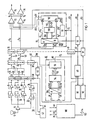
- An on-line correction device for correcting the spatial distortion which is used to practice the method according to the invention, has the reference number 11 in FIG. 1. It is shown in connection with parts of the scintillation camera.
- the scintillation camera of Figure 1 is of the general type that converts scintillation events into electrical signals that represent the location coordinates of each of the scintillation events and their energy. This type is e.g. B. also known as “Anger type”.
- Such scintillation cameras are described, for example, in US Patents 3011 057, 3745345 and 3984689, to which express reference is made for the purpose of extracting further information regarding the structure and functioning of a scintillation camera.
- Scintillation events always occur when e.g. B. gamma rays hit a scintillation crystal on the end face of the camera. They can be detected by means of photomultiplier tubes (one of which is indicated in FIG. 1, for example, with the reference number 12), for which purpose these are arranged behind the scintillation crystal in a predetermined configuration pattern, so that the light energy of each scintillation event can be converted into electrical pulses.
- photomultiplier tubes one of which is indicated in FIG. 1, for example, with the reference number 12
- Normal scintillation cameras work with groups of about 37 to 75 photomultiplier tubes so as to be able to capture the scintillation events across the surface of the scintillation crystal, as shown, for example, in Figures 1 and 2 of the aforementioned U.S. Patent 3745345.
- the pulse outputs of all photomultiplier tubes 12 within the tube arrangement are connected to sample and hold stages 24 via the preamplifier 14, summing and subtracting amplifier J6, integration stages 18, sample and hold stages 20 and multiplier stages 22, which, as in FIG 1 is shown in principle, at its outputs 26, 28 provide the X and Y position coordinates of each scintillation event.
- the output signal of each photomultiplier tube in the tube assembly depends on the proximity of the affected photomultiplier tube to the scintillation event.
- the output signals of the photomultiplier tubes 12 are also fed to an energy analysis circuit 30 for the Z signal.
- the circuit 30 includes a summing amplifier stage 32, an integration stage 34 and two sample and hold stages 36 and 38.
- the output of the sample and hold stage 38 generates at 40 an uncorrected Z signal Z IN which represents the energy of each image event, such as it arises, represents.
- the circuit 30 for the Z signal also includes a processing circuit 42 which is connected to the outputs of the summing amplifier 32 and the integrator 34 and which generates an output signal at 44 for the sample and hold stage 36 and for an equalization and control stage 46 .
- the processing circuit 42 supplies the device with the function of a coarse analyzer on the input side, as it is e.g. B. in US Pat. No.
- the output of the equalization and control stage 46 goes on the one hand to the sample and hold stage 38 and on the other hand to an energy analyzer 48 which has an energy window with a certain width.
- the X and Y coordinate signals at 26 and 28 and the Z energy signal Z IN at 40 are input signals to the energy correction device 10.
- the on-line energy correction device 10 comprises an analog-digital converter 50 which is connected to the outputs 26 and 28 for the X and Y position coordinate signals.
- the analog-to-digital converter 50 provides the outputs 52 with the X and Y position coordinates for each picture event as a digital value on a suitable number of digital control lines.
- the digital output values are given to the addressing input of an energy correction factor memory 54.
- the memory 54 has a data field of energy correction factors stored therein, which are arranged within the data field in such a way that they can be addressed in accordance with information about the coordinates of image field positions, which information represents parts of the area or image carrier of the image field of the camera.
- the energy correction factors are determined in an off-line calibration phase and stored in the energy correction factor memory 54 for the purpose of use during the on-line examination phase of the scintillation camera and the associated apparatus.
- each image event arising from a position X, Y calls via the associated digitized X and Y coordinate signals in the energy cor rectification factor memory 54 an address for a memory cell in which an energy correction factor is stored, which is specifically assigned to the image event from the position X, Y for its energy correction.
- the energy correction value is then read out from the memory.
- the energy correction factor memory 54 in response to each picture event, provides an output signal at 56 on a predetermined number of digital control lines and in a digital format that represents the energy correction factor to suitably match the energy signal at 40 that is also from the picture event originates, in accordance with the pixel at which the event occurred in the image area can be supplied to carry out the correction.
- the digital correction factor which is denoted by f (p) in FIG. 1, is output from the output 56 of the energy correction factor memory 54 to the input of an energy signal correction unit 58 of the energy correction device 10.
- the Z signal Z IN of 40 is also fed as an input signal to the correction unit 58.
- the energy signal correction unit 58 then delivers an corrected energy signal Z c in analog form at an output 60.
- the corrected energy signal Z c at 60 is fed to the input of the energy analyzer 48.
- the energy analyzer 48 now compares the energy level of the corrected energy signal Z c at 60 for each image event with a preselected energy window which is defined by lower and upper energy limits. As a result of the comparison, the analyzer 48 generates an acceptance signal at the output 62 when the corrected energy signal Z c lies within the limits of the preselected energy window. Accordingly, however, it delivers a rejection signal at the output 62 if the energy signal is outside the limits of the energy window.
- the output 62 of the energy analyzer 48 is connected to a light key control stage 64, which controls the associated image display and analysis device via the light key output 66.
- light key control stage 64 determines whether or not an image event should be displayed or possibly counted for analytical purposes.
- the position coordinates of the event to be displayed are derived from the X, Y position coordinate signals at 26, 28. It ultimately determines the correct position of the image event in the image matrix, which is produced by the associated image display and analysis device.
- the output 26 for the X position coordinate signal is connected to a sample and hold stage 70. This generates a signal X a for a first input of an X mixing and spectrum gate 72.
- the output 28 for the Y position coordinate signal is connected to a sample and hold stage 71 which generates a signal Y a which corresponds to the first Input of a Y-mixing and spectrum gate 74 is fed.
- the outputs of the mixing and spectrum gates 72 and 74 are each connected to one of two orientation gates 76 and 78.
- the outputs of the gates 76 and 78 directly control the vertical and horizontal deflection, via which the position of the image event to be displayed is finally determined in the image of the image device or on the analysis device.
- the X-mixing and spectrum gate 72 also has a second input, which is connected to a first output ⁇ X of the correction device 11 for correcting the spatial distortion.
- the Y-mixing and spectrum gate 74 is located with a second input at a second output ⁇ Y of the correction device 11.
- a third input for each of the two gates 72 and 74 is also with the output 83 of a control stage 81 for a spectrum display connected, which is controlled on the one hand by the output signal of the energy analyzer 48 and on the other hand by the corrected energy signal Z c .
- the energy signal correction unit 58 corrects the uncorrected Z energy signal at 40 in accordance with a correction factor f (p) so as to minimize the non-uniformity of the energy response of the scintillation camera as a function of the position of the image event on the camera image area .
- the energy signal correction unit 58 then supplies a corrected energy signal Z c at 60 to the energy analyzer 48, which finally decides whether the image event is accepted for display or whether it is rejected.
- the correction can also be carried out in connection with a single radiation source which itself has a plurality of different energy levels. However, the correction is also possible if the image events originate from a plurality of sources which have different energy levels of the radiation from one another.
- the type of correction remains the same; it is only necessary to provide a correspondingly higher number of energy analyzers with correspondingly different energy windows for evaluating several energy levels. This possibility is indicated in FIG. 1 by adding two further energy analyzers 90 and 92.
- the correction device 11 contains a correction factor memory 108, in which correction factors for correcting the spatial distortion are stored in the form of a predetermined addressable data field.
- the correction factors serve to correct the distortion of image events in the course of the on-line examination phase.
- the correction factors that are stored in the memory 108 were determined in an off-line calibration phase preceding the on-line examination phase.
- this off-line calibration phase the spatial distortion characteristics of the scintillation camera, based on a special reference Energy level, exactly determined.
- the off-line testing, measuring and analyzing apparatus used is not shown in detail. However, it is of a type as described in EP-A-00 21 366 and z. B is shown as a data storage device 14 and computer 16 in FIG. 1 of this application.
- the individual correction factors can of course also be determined in other known ways, for. B. according to one of the methods used in the prior art described above.
- the image area of the scintillation camera is divided into a matrix of 64 horizontal and 64 vertical lines.
- the associated correction factor for the spatial distortion is then determined for the corner points of each surface element of this matrix.
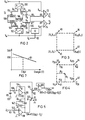
- FIG. 3 shows the correction factors in the form of vectors which indicate the direction of correction. These vectors each attack at the corner points of the individual screen elements of the 64 x 64 matrix. Each vector at a cross point of the matrix is composed of an X correction component and a Y correction component of the correction factor assigned to this cross point.
- the correction factor can therefore be referred to as AV (X, Y) in the following.
- each vector indicates the direction of the correction.
- the respective vector is directed in the opposite direction to that which was measured in the off-line calibration phase as a measure of the spatial distortion.
- the respective vector of the illustration in FIG. 3 thus defines a correction factor which counteracts the measured distortion at the respective point of attack.
- the correction vector therefore places the pixel that was previously incorrectly positioned due to the spatial distortion into the correct position.
- the four correction factor vectors V1, V2, V3, V4 in FIG. 3 thus represent the correction factors in four adjacent points (X i , Y j ), (X i +1, Y i ), (X i , Y i +1), (X i + 1 , Y i + 1) of the 64 x 64 data field.
- the data field is stored in the memory 108 of the correction device 11 for the spatial distortion as a number of coefficients C 1 to C 8 , the sums and differences of the current X and Contain Y-correction factor components of the data field, as they were determined by the off-line test, measurement and analysis apparatus.
- each coefficient C 1 to C 8 is composed of eight bits of information.
- the correction device 11 for the spatial distortion contains an analog-digital converter (ADC) 100 for the X coordinate and an analog-digital converter (ADC) 102 for the Y coordinate .
- the ADC 100 converts the X a position coordinate signal supplied to its analog input into two data streams X u and X L.
- the ADC 102 converts the position coordinate signal Y a supplied to its analog input into two separate data streams Y u and Y L.
- the indices U of the data streams X u and Y u characterize the resulting data in the order of “most significant data x.
- the indices L of X L and Y identify data that are classified as «least significant data».
- the most significant data X u , Y u are fed to the X and Y addressing inputs of the correction factor memory 108 via data lines 104 and 106, respectively.
- the correction factor memory 108 then supplies the coefficients C 1 to C 8 in digital form on a data line 110.
- the data line 110 is connected to the digital data input of a correction interpolator 112.
- This correction interpolator 112 also includes two further data inputs with data lines 114 and 116.
- the least significant data X L are fed to the interpolator via the data line 114.
- the least significant data Y L are fed to the interpolator via line 116.
- These least significant data X L and Y L on the data lines 114 and 116 define the residual functions R x and Ry, as shown in FIG. 4 ′.
- the signal change unit 13 for changing the correction of the spatial distortion now generates an energy change signal ZVR for the correction interpolator 112.
- the stored coefficients C 1 to C 8 of the correction factors are modified in accordance with the level of the energy signal Z c .
- the energy signal Z c arrives on the output line 63 of the sample and hold stage 61 to the signal change unit 13 of the correction device 11.
- correction interpolator 112 is designed in such a way that it carries out the interpolation operations recorded below and converts the results ⁇ X, ⁇ Y into an analog signal form:
- R x and Ry represent the coordinates of the image event within a cell of the data field.
- the correction factors AX and AY which are obtained according to the above operations, are applied to the gates 72 and 74 as corresponding AX and AY analog signals.
- the X a , Y a position coordinate signals of each image event, as supplied by the scintillation camera, are thus corrected by the factors AX and ⁇ Y.
- Energy-level-corrected position coordinate signals X c , Y c are thus obtained. These are corrected for spatial distortion in accordance with the coefficients C 1 to C 8 of the memory 108 depending on the change in the stored coefficients.
- Such a change is carried out by the signal ZVR in the case of a picture event if there is a difference between the energy level of the picture event and that energy level on the basis of which the correction factors in the off-line calibration phase were calculated. The change is directly dependent on the difference between the energy level of the picture event and the last-mentioned energy level.
- the spatial distortion is greater for image events with lower energy levels than for those with higher energy levels.
- This can be done by using two different radioactive sources, e.g. B. Americium 241, which has an energy level of 80 keV, and Barium 133, which has an energy level of 360 keV. If one compares the uncorrected images of both sources, the image of Americium 241 shows increased intensities or so-called "hot spots in the tube center of the photomultiplier tubes, while the image of Barium 133 shows lower intensities or so-called” cold spots "at these points. Americium 241 therefore causes the greater spatial distortion in comparison with barium 133. The amount of distortion thus changes inversely with the level of the energy level of the picture event.
- the signal changing unit 13 corrects a correction factor in inversely proportional to the energy level of the image event when such correction is necessary. As already mentioned before, this correction is always necessary if the energy level of the respective image event is different from that of the reference energy level Z REF . for which the correction factors had been calculated in the off-line calibration phase.
- the signal change unit 13 is used as it is e.g. B. is shown in Figure 5, for changing correction factors, a relationship between the change signal ZVR and the energy of the energy signal Z c in the sense that with linearly decreasing Z c, the change signal ZVR increases linearly (linear opposite relationship).
- the change unit 13 therefore generates a change signal ZVR specifically assigned to it for each image event in response to the energy level which specifically has this event.
- the correction factors measured and stored during the off-line phase are automatically and dynamically adapted to changed conditions from picture event to picture event.
- the correction of the spatial distortion is thus also carried out automatically and dynamically in the right way.
- the scintillation camera therefore always maps any type of energy source from which the image events originate without distortion.
- This source can be a single source that has a plurality of different energy levels; however, the camera can also image a plurality of sources that have different energy levels.
- the linearly opposing relationship between the image event energy signal Z c and the energy change signal ZVR of the change unit 13 in the embodiment according to FIG. 5 is shown in the diagram in FIG.
- the reference energy level Z REF is plotted on the abscissa, for which the correction factors were measured during the off-line calibration phase.
- the reference energy level is, for example, 122 keV.
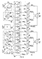
- the signal change unit 13 for changing the correction of the spatial distortion comprises a voltage source with the reference voltage VR, which is on the one hand at ground reference potential 122 and on the other hand at one end of a potentiometer 124, which has the resistance value R2.
- the other end of the potentiometer 124 leads to a switch 126 (S1) which can be switched between two switch positions A and B. In switch position A, the switch connects the second end of potentiometer 124 to ground reference potential 122.
- the potentiometer 124 develops a partial voltage at the potentiometer tap, which is set in position A of the switch S1 so that it assumes the value KVR.
- the partial voltage KVR is fed to the non-inverting input of an amplifier stage 128, which generates the change signal ZVR on the output side.
- the output of amplifier 128 is fed back to the inverting input.
- the reference voltage VR is also connected to the inverting input of an amplifier 132 via an ohmic resistor 130 with the resistance value R.
- the non-inverting input of the amplifier 132 is connected to ground reference potential.
- the output of amplifier 132 is fed back to the inverting input via an ohmic resistor 134, which also has a resistance value of R.
- amplifier 132 thus works as an inverting amplifier with gain one.
- the amplifier accordingly supplies the voltage VR on the output side.
- This output voltage is coupled via an adjustable resistor 136 with the resistance value R4 to the inverting input of an amplifier 138.
- an ohmic resistor 140 which has the resistance value R ; also has the picture event energy signal Z c of 63.
- the non-inverting input of the amplifier 138 again has ground reference potential 122.
- An adjustable feedback resistor 142 with the resistance value R f is connected between the output of the amplifier 138 and the inverting input.
- the settings as discussed are all made with switch S1 in position A.
- the output of the amplifier 138 leads to the switch contact B of the switch 126.
- the resistance value R, of the resistor 142 can be set so that, in accordance with the relationship between Z c and ZVR obtained by measurement and analysis required gain factor K1 according to Figure 7 results.
- the change signal ZVR at the output of the amplifier stage 128 results as follows:
- the correction factor memory 108 contains a total of eight electronically programmable read-only memories 150 to 164, which are called EPROM in common use and in which the coefficients C 1 to C 8 of the correction factors are stored.
- the division between the individual EPROMs is such that the four EPROMs 150, 152, 154, 156 provide the X correction factors C i , C 2 , C 3 and C 4 , while the EPROMs 158, 160, 162 and 164 for the output of the Y correction factors C s to C 8 are responsible. All EPROMs 150 to 164 are addressed by the most significant data bits of the information X u and Y u on lines 104 and 106.
- EPROM's 150 to 164 can store up to 4000 data words, each data word comprising a total of eight bits of information.
- the 64 x 64 matrix of the data field has a total of 4096 picture elements; As already mentioned at the beginning, however, the image area of the camera is circular. For this reason there is always a certain number of picture elements of the square 64 x 64 matrix outside the circle of the camera picture area, so that a 4 K memory (memory content 4 kilobits) is sufficient to store the information actually required.
- each EPROM 150 to 164 is now assigned an 8-bit multiplier digital-to-analog converter 170 to 184 in the interpolator 112, hereinafter referred to as MDAC for short.
- MDAC multiplier digital-to-analog converter
- the connection of each EPROM with the MDAC assigned to it is such that that at the output of an EPROM Correction factor C 1 to C 8 is applied to the digital input of the MDAC.
- the multiplier inputs are the interpolation information shown in FIG.
- the change information ZVR is supplied by the signal change unit 13.
- the change information ZVRR x comes from an MDAC 190 of the interpolator 112, on the digital input of which the least significant bits of the information X L are given via the line 114. As already mentioned, these input data are designated R x .
- the information ZVR is fed to the multiplier input by the change unit 13.
- the remaining information ZVRRy and ZVRR xR y are accordingly provided by two further MDACs 192 and 194 of the interpolator 112. Both MDAC's are fed at the digital input via line 116 with the least significant information of the signal Y in the form of Ry.
- the signal ZVR is again present at the multiplier input of the MDAC 192.
- the output signal ZVRR X of the MDAC 190 is present at the multiplier input of the MDAC 194.
Landscapes
- Physics & Mathematics (AREA)
- Health & Medical Sciences (AREA)
- Engineering & Computer Science (AREA)
- Biomedical Technology (AREA)
- General Health & Medical Sciences (AREA)
- Medical Informatics (AREA)
- Nuclear Medicine, Radiotherapy & Molecular Imaging (AREA)
- Optics & Photonics (AREA)
- Life Sciences & Earth Sciences (AREA)
- General Physics & Mathematics (AREA)
- High Energy & Nuclear Physics (AREA)
- Molecular Biology (AREA)
- Spectroscopy & Molecular Physics (AREA)
- Nuclear Medicine (AREA)
Claims (13)


Applications Claiming Priority (2)
| Application Number | Priority Date | Filing Date | Title |
|---|---|---|---|
| US06/096,182 US4316257A (en) | 1979-11-20 | 1979-11-20 | Dynamic modification of spatial distortion correction capabilities of scintillation camera |
| US96182 | 1993-07-23 |
Publications (2)
| Publication Number | Publication Date |
|---|---|
| EP0029569A1 EP0029569A1 (fr) | 1981-06-03 |
| EP0029569B1 true EP0029569B1 (fr) | 1988-02-10 |
Family
ID=22256131
Family Applications (1)
| Application Number | Title | Priority Date | Filing Date |
|---|---|---|---|
| EP80107129A Expired EP0029569B1 (fr) | 1979-11-20 | 1980-11-17 | Procédé et dispositif de correction de la distorsion spatiale dans une caméra à scintillation |
Country Status (5)
| Country | Link |
|---|---|
| US (1) | US4316257A (fr) |
| EP (1) | EP0029569B1 (fr) |
| JP (1) | JPS5686378A (fr) |
| DE (1) | DE3072077D1 (fr) |
| DK (1) | DK492580A (fr) |
Families Citing this family (24)
| Publication number | Priority date | Publication date | Assignee | Title |
|---|---|---|---|---|
| FR2479990A1 (fr) | 1980-04-04 | 1981-10-09 | Labo Electronique Physique | Dispositif electronique de correction des defauts de linearite d'une camera de gammagraphie de type anger |
| JPS57570A (en) * | 1980-06-02 | 1982-01-05 | Toshiba Corp | Scintillation camera device |
| US4432059A (en) * | 1980-09-03 | 1984-02-14 | Elscint Ltd. | Scanning gamma camera |
| US4566074A (en) * | 1981-10-08 | 1986-01-21 | Tokyo Shibaura Denki Kabushiki Kaisha | Scintillation camera |
| US4466075A (en) * | 1981-11-23 | 1984-08-14 | Siemens Gammasonics, Inc. | Motion correction circuitry and method for a radiation imaging device |
| US4611283A (en) * | 1981-12-30 | 1986-09-09 | Raytheon Company | Radiographic imaging apparatus and methods for operating such apparatus |
| US4528639A (en) * | 1982-10-29 | 1985-07-09 | The United States Of America As Represented By The Administrator Of The National Aeronautics And Space Administration | Method of and apparatus for generating an inerstitial point in a data stream having an even number of data points |
| US4583187A (en) * | 1983-02-02 | 1986-04-15 | Siemens Gammasonics, Inc. | Method and circuit for stabilizing conversion gain of radiation detectors of a radiation detection system |
| US4575810A (en) * | 1983-03-11 | 1986-03-11 | Siemens Gammasonics, Inc. | Method and circuit for processing pulses by applying the technique of weighted acquisition |
| JPS61110078A (ja) * | 1984-11-02 | 1986-05-28 | Toshiba Corp | 核医学デ−タ処理装置 |
| CA1280224C (fr) * | 1987-08-27 | 1991-02-12 | Daniel Gagnon | Methode et circuit de traitement de signaux a bande etroite se trouvant dans une bande large comportant une perturbation |
| JP3165861B2 (ja) * | 1990-06-12 | 2001-05-14 | セイコープレシジョン株式会社 | カメラの特性誤差補正装置 |
| US5171998A (en) * | 1990-06-14 | 1992-12-15 | Engdahl John C | Gamma ray imaging detector |
| US5354991A (en) * | 1993-03-01 | 1994-10-11 | The United States Of America As Represented By The Unites States Department Of Energy | Apparatus and method for detecting full-capture radiation events |
| US5345082A (en) * | 1993-03-22 | 1994-09-06 | Sopha Medical Systems, Inc. | Scintillation camera utilizing energy dependent linearity correction |
| US5338937A (en) * | 1993-06-14 | 1994-08-16 | Sloan-Kettering Institute For Cancer Research | Radiation imaging device having an enlarged uniform field of view |
| US5576547A (en) * | 1993-07-27 | 1996-11-19 | Park Medical Systems Inc. | Position calculation and energy correction in the digital scintillation camera |
| US5504333A (en) * | 1994-07-29 | 1996-04-02 | Kabushiki Kaisha Toshiba | Scintillation camera |
| US6002434A (en) * | 1997-01-14 | 1999-12-14 | Matsushita Electric Industrial Co., Ltd. | Registration correction waveform determination method and system for a television camera |
| US7417232B2 (en) * | 2005-06-17 | 2008-08-26 | Siemens Medical Solutions Usa, Inc. | Systems and methods for camera calibration |
| US7208739B1 (en) * | 2005-11-30 | 2007-04-24 | General Electric Company | Method and apparatus for correction of pileup and charge sharing in x-ray images with energy resolution |
| WO2012065130A2 (fr) * | 2010-11-12 | 2012-05-18 | Saint-Gobain Ceramics & Plastics, Inc. | Système de détection de rayonnement et son procédé d'utilisation |
| CN112525107B (zh) * | 2020-11-24 | 2022-09-09 | 浙江知象光电科技有限公司 | 一种基于事件相机的结构光三维测量方法 |
| CN112882084B (zh) * | 2021-01-18 | 2022-05-24 | 明峰医疗系统股份有限公司 | 非线性在线修正方法、系统及计算机可读存储介质 |
Citations (2)
| Publication number | Priority date | Publication date | Assignee | Title |
|---|---|---|---|---|
| US3745345A (en) * | 1971-11-09 | 1973-07-10 | Nuclear Chicago Corp | Radiation imaging device |
| EP0021366A1 (fr) * | 1979-06-22 | 1981-01-07 | Siemens Aktiengesellschaft | Procédé et dispositif de correction de la distorsion spatiale pour caméras à scintillation |
Family Cites Families (3)
| Publication number | Priority date | Publication date | Assignee | Title |
|---|---|---|---|---|
| US3872434A (en) * | 1973-12-05 | 1975-03-18 | Recognition Equipment Inc | Dynamic sample-by-sample automatic gain control |
| US4157533A (en) * | 1977-11-25 | 1979-06-05 | Recognition Equipment Incorporated | Independent channel automatic gain control for self-scanning photocell array |
| US4212061A (en) * | 1977-12-21 | 1980-07-08 | Medtronic, Inc. | Radiation signal processing system |
-
1979
- 1979-11-20 US US06/096,182 patent/US4316257A/en not_active Expired - Lifetime
-
1980
- 1980-11-17 EP EP80107129A patent/EP0029569B1/fr not_active Expired
- 1980-11-17 DE DE8080107129T patent/DE3072077D1/de not_active Expired
- 1980-11-18 JP JP16253480A patent/JPS5686378A/ja active Granted
- 1980-11-19 DK DK492580A patent/DK492580A/da not_active Application Discontinuation
Patent Citations (2)
| Publication number | Priority date | Publication date | Assignee | Title |
|---|---|---|---|---|
| US3745345A (en) * | 1971-11-09 | 1973-07-10 | Nuclear Chicago Corp | Radiation imaging device |
| EP0021366A1 (fr) * | 1979-06-22 | 1981-01-07 | Siemens Aktiengesellschaft | Procédé et dispositif de correction de la distorsion spatiale pour caméras à scintillation |
Also Published As
| Publication number | Publication date |
|---|---|
| JPH0119111B2 (fr) | 1989-04-10 |
| JPS5686378A (en) | 1981-07-14 |
| DK492580A (da) | 1981-05-21 |
| EP0029569A1 (fr) | 1981-06-03 |
| US4316257A (en) | 1982-02-16 |
| DE3072077D1 (en) | 1988-03-17 |
Similar Documents
| Publication | Publication Date | Title |
|---|---|---|
| EP0029569B1 (fr) | Procédé et dispositif de correction de la distorsion spatiale dans une caméra à scintillation | |
| EP0029244B1 (fr) | Procédé et dispositif de correction des irrégularités dans la réponse en énergie d'une caméra à scintillation | |
| DE69323531T2 (de) | Ungleichförmigkeitsausgleich mit grossem Dynamikbereich für infrarote Bildebenematrizen | |
| DE3886323T2 (de) | Interpolationsverfahren. | |
| DE3404066C2 (fr) | ||
| DE2254506C2 (fr) | ||
| EP0194477B1 (fr) | Dispositif de balayage à rayons X | |
| DE19648211A1 (de) | Kernmedizinisches Verfahren | |
| DE68913543T2 (de) | Vorrichtung und verfahren zur messung der aktivität radioaktiver muster, die mehrere radioaktive isotope enthalten. | |
| EP0253060A1 (fr) | Dispositif de balayage à rayons X | |
| DE2503978B2 (de) | Vorrichtung zur Untersuchung eines Körpers mit durchdringender Strahlung | |
| DE102011077859A1 (de) | Quantenzählender Strahlungsdetektor | |
| DE68923560T2 (de) | Ablenkkorrektursystem mit Speicherabbildung. | |
| DE3403457A1 (de) | Verfahren und schaltungsanordnung zum abstimmen der strahlungsdetektoren eines strahlungsanzeigegeraetes | |
| DE2641775A1 (de) | Strahlungsabbildungseinrichtung | |
| EP0365786B1 (fr) | Méthode de détermination de la fonction de transfert d'une caméra vidéo | |
| DE2725750A1 (de) | Verfahren und vorrichtung zur bestimmung des quench-effektes bei szintillationszaehlern mit fluessigem szintillator | |
| DE69621743T2 (de) | Gammakamera mit Streukorrekturbildes | |
| DE69528949T2 (de) | Verbessertes Gammakamera-System | |
| DE69323257T2 (de) | Nuklearmedizinische Bildwiedergabe - Einrichtung | |
| DE10112792A1 (de) | Verfahren zur Korrektur einer Kalibrierwerte enthaltenden Kalibriertabelle eines CT-Geräts | |
| DE102004039681B4 (de) | Tomographiegerät und Verfahren für ein Tomographiegerät | |
| DE102010061586A1 (de) | Systeme und Verfahren zum Erzeugen von Kalibrierungskennfeldern für nicht-pixelartig aufgebaute Gamma-Detektoren | |
| DE69004899T2 (de) | Verfahren zur Korrektur der Signale von einem linearen Strahlungsdetektor und Korrekturvorrichtung zur Anwendung dieses Verfahrens. | |
| DE1764603B2 (de) | Verfahren zum automatischen kompensieren von auf loeschvorgaengen beruhenden spektralen verschiebungen bei einem fluessigkeitsszintillationszaehler |
Legal Events
| Date | Code | Title | Description |
|---|---|---|---|
| PUAI | Public reference made under article 153(3) epc to a published international application that has entered the european phase |
Free format text: ORIGINAL CODE: 0009012 |
|
| AK | Designated contracting states |
Designated state(s): DE FR GB NL |
|
| 17P | Request for examination filed |
Effective date: 19810415 |
|
| GRAA | (expected) grant |
Free format text: ORIGINAL CODE: 0009210 |
|
| AK | Designated contracting states |
Kind code of ref document: B1 Designated state(s): DE FR GB NL |
|
| REF | Corresponds to: |
Ref document number: 3072077 Country of ref document: DE Date of ref document: 19880317 |
|
| ET | Fr: translation filed | ||
| GBT | Gb: translation of ep patent filed (gb section 77(6)(a)/1977) | ||
| PG25 | Lapsed in a contracting state [announced via postgrant information from national office to epo] |
Ref country code: GB Effective date: 19881117 |
|
| PLBE | No opposition filed within time limit |
Free format text: ORIGINAL CODE: 0009261 |
|
| STAA | Information on the status of an ep patent application or granted ep patent |
Free format text: STATUS: NO OPPOSITION FILED WITHIN TIME LIMIT |
|
| 26N | No opposition filed | ||
| GBPC | Gb: european patent ceased through non-payment of renewal fee | ||
| PGFP | Annual fee paid to national office [announced via postgrant information from national office to epo] |
Ref country code: DE Payment date: 19900126 Year of fee payment: 10 |
|
| PG25 | Lapsed in a contracting state [announced via postgrant information from national office to epo] |
Ref country code: DE Effective date: 19910801 |
|
| PGFP | Annual fee paid to national office [announced via postgrant information from national office to epo] |
Ref country code: NL Payment date: 19911130 Year of fee payment: 12 |
|
| PG25 | Lapsed in a contracting state [announced via postgrant information from national office to epo] |
Ref country code: NL Effective date: 19930601 |
|
| NLV4 | Nl: lapsed or anulled due to non-payment of the annual fee | ||
| PGFP | Annual fee paid to national office [announced via postgrant information from national office to epo] |
Ref country code: FR Payment date: 19951123 Year of fee payment: 16 |
|
| PG25 | Lapsed in a contracting state [announced via postgrant information from national office to epo] |
Ref country code: FR Effective date: 19970731 |
|
| REG | Reference to a national code |
Ref country code: FR Ref legal event code: ST |