EP0029672B1 - Elektrischer Sicherheits-Initialzünder - Google Patents
Elektrischer Sicherheits-Initialzünder Download PDFInfo
- Publication number
- EP0029672B1 EP0029672B1 EP80303921A EP80303921A EP0029672B1 EP 0029672 B1 EP0029672 B1 EP 0029672B1 EP 80303921 A EP80303921 A EP 80303921A EP 80303921 A EP80303921 A EP 80303921A EP 0029672 B1 EP0029672 B1 EP 0029672B1
- Authority
- EP
- European Patent Office
- Prior art keywords
- casing
- static discharge
- sleeve
- charge
- wires
- Prior art date
- Legal status (The legal status is an assumption and is not a legal conclusion. Google has not performed a legal analysis and makes no representation as to the accuracy of the status listed.)
- Expired
Links
- 239000003999 initiator Substances 0.000 title description 4
- 230000003068 static effect Effects 0.000 claims description 55
- 229910000859 α-Fe Inorganic materials 0.000 claims description 17
- 239000000758 substrate Substances 0.000 claims description 15
- WABPQHHGFIMREM-UHFFFAOYSA-N lead(0) Chemical compound [Pb] WABPQHHGFIMREM-UHFFFAOYSA-N 0.000 claims description 13
- 239000000463 material Substances 0.000 claims description 8
- 239000004020 conductor Substances 0.000 claims description 6
- 230000000977 initiatory effect Effects 0.000 claims description 5
- -1 polymonochloroparaxylylene Polymers 0.000 claims description 4
- 239000011248 coating agent Substances 0.000 claims description 2
- 238000000576 coating method Methods 0.000 claims description 2
- 239000012815 thermoplastic material Substances 0.000 claims 2
- 229910052729 chemical element Inorganic materials 0.000 claims 1
- RYGMFSIKBFXOCR-UHFFFAOYSA-N Copper Chemical compound [Cu] RYGMFSIKBFXOCR-UHFFFAOYSA-N 0.000 description 11
- 229910052802 copper Inorganic materials 0.000 description 11
- 239000010949 copper Substances 0.000 description 11
- 229910052751 metal Inorganic materials 0.000 description 9
- 239000002184 metal Substances 0.000 description 9
- 238000000034 method Methods 0.000 description 7
- 238000009413 insulation Methods 0.000 description 6
- 239000011888 foil Substances 0.000 description 5
- 239000011521 glass Substances 0.000 description 5
- 239000000203 mixture Substances 0.000 description 4
- 230000005611 electricity Effects 0.000 description 3
- RTAQQCXQSZGOHL-UHFFFAOYSA-N Titanium Chemical compound [Ti] RTAQQCXQSZGOHL-UHFFFAOYSA-N 0.000 description 2
- ZACISHMWZUXBDS-UHFFFAOYSA-L barium(2+);2,4,6-trinitrobenzene-1,3-diolate Chemical compound [Ba+2].[O-]C1=C([N+]([O-])=O)C=C([N+]([O-])=O)C([O-])=C1[N+]([O-])=O ZACISHMWZUXBDS-UHFFFAOYSA-L 0.000 description 2
- 238000005452 bending Methods 0.000 description 2
- 239000003990 capacitor Substances 0.000 description 2
- AXZAYXJCENRGIM-UHFFFAOYSA-J dipotassium;tetrabromoplatinum(2-) Chemical compound [K+].[K+].[Br-].[Br-].[Br-].[Br-].[Pt+2] AXZAYXJCENRGIM-UHFFFAOYSA-J 0.000 description 2
- 238000005530 etching Methods 0.000 description 2
- 239000004033 plastic Substances 0.000 description 2
- 229920003023 plastic Polymers 0.000 description 2
- 239000002985 plastic film Substances 0.000 description 2
- 229910001487 potassium perchlorate Inorganic materials 0.000 description 2
- 239000003566 sealing material Substances 0.000 description 2
- 229910000679 solder Inorganic materials 0.000 description 2
- 239000010936 titanium Substances 0.000 description 2
- 229910052719 titanium Inorganic materials 0.000 description 2
- KXGFMDJXCMQABM-UHFFFAOYSA-N 2-methoxy-6-methylphenol Chemical compound [CH]OC1=CC=CC([CH])=C1O KXGFMDJXCMQABM-UHFFFAOYSA-N 0.000 description 1
- RZVAJINKPMORJF-UHFFFAOYSA-N Acetaminophen Chemical compound CC(=O)NC1=CC=C(O)C=C1 RZVAJINKPMORJF-UHFFFAOYSA-N 0.000 description 1
- 239000004677 Nylon Substances 0.000 description 1
- 239000004698 Polyethylene Substances 0.000 description 1
- 208000027418 Wounds and injury Diseases 0.000 description 1
- PNEYBMLMFCGWSK-UHFFFAOYSA-N aluminium oxide Inorganic materials [O-2].[O-2].[O-2].[Al+3].[Al+3] PNEYBMLMFCGWSK-UHFFFAOYSA-N 0.000 description 1
- 239000011230 binding agent Substances 0.000 description 1
- 238000002485 combustion reaction Methods 0.000 description 1
- 230000006378 damage Effects 0.000 description 1
- 239000003822 epoxy resin Substances 0.000 description 1
- 239000002360 explosive Substances 0.000 description 1
- 238000010304 firing Methods 0.000 description 1
- 238000013467 fragmentation Methods 0.000 description 1
- 238000006062 fragmentation reaction Methods 0.000 description 1
- 238000001746 injection moulding Methods 0.000 description 1
- 208000014674 injury Diseases 0.000 description 1
- 239000011810 insulating material Substances 0.000 description 1
- 238000011031 large-scale manufacturing process Methods 0.000 description 1
- 230000007246 mechanism Effects 0.000 description 1
- 238000003801 milling Methods 0.000 description 1
- 238000012986 modification Methods 0.000 description 1
- 230000004048 modification Effects 0.000 description 1
- 229920001778 nylon Polymers 0.000 description 1
- ISWSIDIOOBJBQZ-UHFFFAOYSA-N phenol group Chemical group C1(=CC=CC=C1)O ISWSIDIOOBJBQZ-UHFFFAOYSA-N 0.000 description 1
- 239000005011 phenolic resin Substances 0.000 description 1
- 229920001568 phenolic resin Polymers 0.000 description 1
- 229920000647 polyepoxide Polymers 0.000 description 1
- 229920000573 polyethylene Polymers 0.000 description 1
- 229920001343 polytetrafluoroethylene Polymers 0.000 description 1
- 239000004810 polytetrafluoroethylene Substances 0.000 description 1
- 239000000843 powder Substances 0.000 description 1
- 238000002360 preparation method Methods 0.000 description 1
- 239000007787 solid Substances 0.000 description 1
- 229920001169 thermoplastic Polymers 0.000 description 1
- 239000004416 thermosoftening plastic Substances 0.000 description 1
- 238000001771 vacuum deposition Methods 0.000 description 1
Images

Classifications
-
- F—MECHANICAL ENGINEERING; LIGHTING; HEATING; WEAPONS; BLASTING
- F42—AMMUNITION; BLASTING
- F42B—EXPLOSIVE CHARGES, e.g. FOR BLASTING, FIREWORKS, AMMUNITION
- F42B3/00—Blasting cartridges, i.e. case and explosive
- F42B3/10—Initiators therefor
- F42B3/18—Safety initiators resistant to premature firing by static electricity or stray currents
Definitions
- This invention relates to electroexplosive devices and more particularly to an electroexplosive device (EED) which is useful in automotive airbags.
- EED electroexplosive device
- EED electroexplosive device
- squibs initiators
- electric initiators electric detonators
- electrically initiated matches electrically initiated matches
- Airbags have been suggested as a means for protecting passengers of automobiles and other vehicles from injury due to striking a part of the vehicle (such as the windshield or dash board) in the event of rapid deceleration, which may occur in the event of a crash.
- An advantage of the airbag over other passenger restraint devices, such as seat belts, is that the airbag is initiated automatically by rapid deceleration and does not require any action on the part of a passenger (such as fastening a seat belt).
- a semiconductive plug presents a conductive discharge path for high voltage discharges and a high resistance path for the low voltages normally used to fire EED's.
- Disadvantages of semiconductive mixes are twofold. First of all, dielectric strength and insulation resistance are relatively low and variable. The second disadvantage is that the static discharge mix is of paste consistency and must be introduced into the EED in precise amounts, which is difficult and expensive because of the small sizes of most EED's.
- U.S. Patent 3,333,538 to Schnettler shows a thin nonconductive plastic sheet having a plurality of conductive hexagon-shaped areas, separated by spark gaps formed by the uncoated spaces between the hexagons.
- the hexagons are dimensioned so that one gap is always provided between each lead wire and the shell, and so that there is always at least one gap between the lead wires.
- the plastic sheet is pierced by the lead wires during assembly, which results in firm electrical contact between the lead wires and the conductive areas of the sheet.
- One disadvantage of the Schnettler structure is that the sheet must be oriented during assembly so that the rows of hexagons are parallel to the line connecting centers of the lead wires.
- Another disadvantage is there is some danger of bending the lead wires during assembly, because no clearance is provided between the leads and the sheet.
- Another disadvantage is that the leads must be straight at the time of assembly of the static shunt device. Also, the distance between lead wires must equal or exceed the distance from either lead wire to the casing.
- This static discharge device comprises a tab of metallic foil which is connected to the metallic casing of the EED and which has a pair of points that are in proximity with the lead wires of the EED.
- This structure provides a pair of spark gaps from each of the lead wires to the metal foil.
- Proper operation of this device depends on precise control of spark gap distances, so that currents induced by static electricity will jump across the spark gaps from the leads to the metal foil.
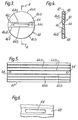
- FIG. 1 Another type of static shunt device is illustrated in GB-A-2018959 (Fig 3). This device comprises a spark gap between the housing crimp 38 and the edge 49 of a metal foil lining 47, that is in direct contact with one of the leads at 53.
- U.S. Patent 4,061,088 to Ueda discloses an EED containing a nonlinear resistor element which prevent ignition in the event of a static discharge.
- an electroexplosive device comprising an electrically conductive casing containing, a heat-ignitable charge, means for igniting said charge including a bridge element in proximity with the charge and conductor means comprising at least one lead wire for supplying an electric current to the bridge element, means for preventing accidental electrostatic discharge of the device, and means inside the casing for preventing accidental radio frequency (RF) discharge.
- RF radio frequency
- the means for preventing accidental electrostatic discharge is a static discharge element comprising a non-conductive substrate having a central opening to permit the lead wire or wires to extend therethrough, and a thin electrically conductive layer covering a portion of at least one face of the substrate.
- the conductive layer is in electrical contact with the casing but is out of electrical contact with the heat-ignitable charge, the central opening and the lead wire (or wires) and has a boundary of which an inner portion is disposed in proximity with, but entirely out of contact with, the adjacent edge of the central opening, whereby a spark gap is provided between the lead wires and the conductive layer.
- the means for protecting the device against accidental RF initiation is a ferrite sleeve having one or more openings extending longitudinally therethrough for the lead wire (or wires), means for insulating the sleeve from the lead wire (or wires), and means for providing electrical contact between the sleeve and the casing.
- the preferred electroexplosive device according to this invention is an igniter as shown in FIGS. 1 and 2.
- Casing 12 is preferably a cylindrical metallic casing which is open at one end and closed at the other end.
- Casing 12 is formed by cylindrical metal sleeve 12a and a cup-shaped metallic member comprising a cylindrical wall 12b which is a press fit inside sleeve 12a, and a circular end wall 12c which closes one end of the casing 12.
- End wall 12c is scored with a plurality of diametric grooves 12d (four are shown in FIG. 2), so that the end wall will assume a petal configuration and avoid fragmentation when the device is fired.
- EED 10 which are located inside the casing 12 will be described in the order in which they are located in the assembled device, beginning at the closed end and proceeding toward the open end of the casing.
- a base charge 14 of powdered igniter material preferably a titanium/potassium perchlorate mixture, is located inside casing 12 adjacent the closed end thereof.
- a heat ignitable charge 16 and charge holder 18 therefor are next to the base charge 14 and a heat ignitable charge 16 and charge holder 18 therefor.
- the heat ignitable charge 16 is preferably pressed barium styphnate but may be another heat ignitable material which in combustion liberates enough heat to ignite the base charge 14.
- the charge holder 18 is an annular plastic member, preferably made of glass-filled nylon. The central opening of charge holder 18 contains the ignition charge 16, and the outer wall abuts the casing 12. Charge holder 18 has a shoulder 18a.
- the electroexplosive device 10 is provided with means for igniting ignition charge 16 including a bridge element 20 and conductor means (shown as conductors 22, 24) including leads 22a, 24a for supplying an electric current to the bridge element 20.
- Bridge element 20 is in proximity with the ignition charge 16 and the shoulder 18a.
- Bridge element 20 may consist of either one or two wires connecting the ends of lead wires 22a, 24a. The use of two bridge wires instead of one reduces the chance that there will be no operative wire.
- Leads 22a, 24a extend longitudinally from bridge element 20 toward the open end of the casing 12.
- Conductors 22, 24 also include metallic connectors 22b, 24b in the form of sleeves, and external wires 22c, 24c, respectively.
- the leads 22a, 24a are bent at 22d and 24d in order to provide enough space to prevent short circuiting between connectors 22b and 24b while maintaining the leads close enough together at the bottom so that the bridge element 20 will have the desired characteristics.
- External wires 22c, 24c extend through the open end of casing 12. External wires 22c, 24c may be covered by insulation 22e, 24e.
- a glass plug 26 and concentric metal header 28 Surrounding lead wires 22a, 24a are a glass plug 26 and concentric metal header 28.
- the middle portion of the outer wall of header 28 abuts the inner wall of casing 12.
- the end portions of the outer wall are of smaller radius than the middle portion, to provide fitting engagement with the charge holder 18 and to provide a recess for a ring 30 of solder material.
- the inner wall of header 28 abuts glass plug 26.
- a glass- to-metal seal is formed between the glass plug on the one hand and the leads 22a, 24a and the header 28 on the other.
- the base charge 16, charge holder 18, bridge element 20, leads 22a, 24a, glass plug 26 and header 28 are preferably formed into an ignition assembly prior to assembly of the complete electroexplosive device 10.
- a static discharge disc 40 rests on the upper end of header 28. Static discharge disc 40 harmlessly dissipates currents which are due to static electricity. The static discharge disc 40 will subsequently be described in detail with reference to FIGS. 3 and 4.
- a nonconductive separator 50 of suitable plastic material such as polytetrafluoroethylene, is placed above the static discharge disc 40 to separate the disc from ferrite sleeve 52.
- a ferrite sleeve 52 surrounding the lead wires is disposed above the separator 50.
- Ferrite sleeve 52 has opening means comprising one or more openings (one for each lead).
- the sleeve 52 has two openings in the preferred embodiment shown.
- a thin layer or coating 56 of a thermoplastic insulating material, such as polymonochloroparaxylylene, is applied to the insides of these openings preferably by vacuum deposition, in order to provide insulation between the sleeve 52 and the lead wires 22a and 24a passing there through.
- An electrically conductive solder layer is placed between the outside diameter of sleeve 52 and the inside wall of casing 12 in order to provide good electrical contact between the ferrite sleeve 52 and the casing 12.
- a mass 60 of waterproof nonconductive sealing material closes the open end of the casing 12.
- a conventional two-part epoxy resin may be used as the sealing material.
- the static discharge disc 40 will now be described with reference to FIGS. 3 and 4.
- the details of the static discharge disc do not form a part of the present invention, but are described and claimed in the copending application of Donald M. Stonestrom, filed of even date herewith and entitled Static Discharge Disc.
- static discharge disc 40 has a nonconductive circular substrate 42 which is preferably made of phenolic printed circuit board material. Other rigid substrate materials can be used.
- the substrate 42 includes an opening or slot 44 of oblong shape, having opposed parallel sides 44a, 44b, and semicircular end portions 44c.
- the slot 44 is preferably centered so that the parallel sides 44a, 44b lie at approximately equal distances from a diameter of disc 40.
- the width of the slotted opening 44 i.e., the distance between parallel sides 44a and 44b
- Portions of both faces of substrate 42 are coated with electrically conductive layers 46, 48, preferably of copper.
- Conductive layer 46 has two portions 46a, 46b of the same size and shape, each in the shape of a segment of a circle, and separated from each other by a nonconductive portion of the substrate.
- Portion 46a extends from its inner boundary 46c, which is a straight line parallel to and in proximity with, but spaced from, edge 44a of opening 44, to outer boundary 46e, which lies along the circumference of disc 40.
- the electrically conductive portion 46b extends from its inner boundary 46d, which is a straight line close to but spaced from the edge 44b of opening 44, to its outer boundary 46f along the circumference of the disc 40.
- the portion of substrate 42 between the two conductive portions 46a and 46b is uncoated and therefore nonconductive.
- the preferred static discharge disc 40 is coated with electrically conductive layers on both sides so that it will not be necessary to place the disc in any particular orientation during assembly of the EED 10.
- the static discharge disc can be provided with an electrically conductive layer on one side only if desired; however, in that case it is necessary during assembly of an EED to be sure that the side having the conductive layer is placed face down so that the conductive layer will be in registry with the conductive header 28 in the assembled device.
- Two holes 64 are punched near either end of the strip 62 and midway between the two long sides. These holes are used as reference holes for die sets and feeding mechanisms.
- a plurality of oblong slots 44 aligned in rows are punched.
- a punch press having a die which will form the desired oblong slots is used.
- All slots may be punched at one time; however, where required by limitations in the punch press or die, one may punch three rows at a time, turn the strip around, and punch the other three rows. Also, one may punch the holes over a length of several inches, advance the strip, and so on until the entire length of the strip has been punched. It is possible to obtain very precise spacing of slots and alignment of rows in this manner.
- copper is removed by known etching techniques to form six rows 68 in which copper has been removed. These rows are aligned with and slightly wider than the slots 44. Precise positioning of these rows 68, and removal of all copper from the sides of slots 44, can be achieved through use of the two reference holes 64. After removal of the copper from these rows, the work piece 62 is once again placed in a punch press, clamped at 64, and the static discharge discs are punched out with a circular punch.
- the method of preparing static discharge discs described herein has pronounced advantages over other methods previously tried for making static discharge discs.
- the present method is suitable for large scale production of static discharge discs, the areas of bare substrate may be precisely aligned with the holes 44 so that there is no danger that copper will touch the edges of the slot, and the reject rate is quite low.
- the use of etching instead of other techniques for removing copper, such as milling is a particularly important factor in obtaining the required precise alignment of the rows of bare substrate with the rows of oblong slots.
- the present invention will now be described with reference to a specific embodiment thereof.
- This specific embodiment is constructed in accordance with the drawings herein, having a length not exceeding 2.8 cm (1.1 inch) and having a diameter of 0.76 cm (0.3 inch).
- the base charge consists of 90 mg of titanium/potassium perchlorate mixture pressed at 3500 Ncm- 2 .
- the ignition charge consists of 9 mg. of barium styphnate, having a moisture content not over 0.5%, which is pressed at 17000 Ncm- 2 .
- Lead wires 22a, 24a are 0.1 cm in diameter.
- the static discharge disc is 0.66 cm in diameter, 0.08 cm thick (including the copper layers on either side, each of which is about 0.01 cm thick), with a slot width of 0.11 cm and a copper-free substrate width of 0.13 cm.
- the EED of the present invention is particularly useful as the initiator or passive restraint devices, popularly known as airbags, for automobiles.
- the EED may be used to ignite a heat generating cartridge which imparts additional energy to a stored gas source which inflates the airbag.
- One of the requirements for an EED in this service is that the EED shall not function when subjected to the discharge from a 500 picofarad capacitor charged to 25,000 volts, the discharge being applied through the leads (which are connected together) to the casing through a series resistance of 5,000 ohms.
- Electroexplosive devices according to this invention are capable of meeting that requirement.
- the static discharge disc of FIGS. 3 and 4 offers major advantages over prior art structure for dissipating static charges.
- a major advantage of the static discharge disc herein is a high degree of reliability.
- the gap between the edges 44a, 44b of the slot 44 and the adjacent boundaries 46c, 46d of the copper-covered area of the disc assures that there will always by a spark gap between the lead wires 22a, 24a and the copper-covered area, even when the lead wires touch an edge of the slot.
- the spark gap between the lead wires and the copper-covered area will never be too large for effective operation, because the disc can be formed to close tolerances and is virtually incapable of incorrect assembly (other than to place the wrong side in contact with metal sleeve 28 when a disc which is copper covered on only one side is used).
- the static discharge disc herein also has high dielectric strength and insulation resistance.
- static discharge disc herein is that it can be used with a wide variety of EED's. In other words, the static discharge disc does not impose any significant structural limitations on the EED.
- static discharge disc is a solid member and can therefore be assembled into an EED more easily than can be the paste consistency static shunt mixes which must be introduced by injection molding techniques or other techniques suitable for handling pastes.
- the present static discharge disc satisfies the need for static discharge device and associated EED which have a high degree of reliability, high dielectric stength, ease of assembly, and low cost.
- the igniter shown in FIGS 1 and 2 also possesses advantages not found in prior art devices. First of all, the ignitor herein will not fire or be degraded by discharges from a 500 picofarad capacitor charged to 25,000 volts, when fired through a 5,000 ohm resistor either pin to pin or pin to case. This advantage accrues primarily as result of using the static discharge disc shown in FIGS. 3 and 4.
- the igniter of FIGS. 1 and 2 also possesses all of the other advantages stated above which result from the use of the static discharge disc shown herein.
- the igniter herein is also capable of meeting an all-fire requirement of 3.5 amp. and a 3 mili-second pulse, and a no-fire requirement of 0.75 amp. for 10 seconds minimum. Also, the igniter herein has an after fire resistance of 1,000 ohms minimum pin-to-pin and pin-to-case at 24 volts dc, measured from 1 to 200 ms after application of a 3.0 ms firing pulse.
- the igniter herein also has good RF attenuation.
- the igniter will not fire when RF power is delivered as follows: 4.0 watts at a frequency from 1 MHz to 12 GHz; or 2.0 watts at 5 MHz; or 0.5 watts at 1 MHz. Much better results in both pin-to-pin and pin-to-case test modes have been achieved.
- the present igniter structure also assures good electrical contact between the ferrite sleeve and the casing, and insulation between the ferrite sleeve and the lead wires.
- a further advantage of the igniter herein is that good RF protection is achieved with the ferrite sleeve alone, without possibility of current flow through the ferrite sleeve under normal conditions, by virtue of good electrical contact between the ferrite sleeve and the casing and insulation between the ferrite sleeve and the lead.
- a further advantage of the igniter herein is that, by using both the ferrite sleeve and the static discharge element shown and described herein, good RF protection and good electrostatic protection are achieved in a compact EED.
- an EED according to this invention may have either 1, 2, or 4 lead wires, and the static discharge disc will be shaped accordingly. In all cases the inner boundary of the copper layer on the static discharge disc will be close to but spaced from the edge of the opening for the lead wire or wires.
- One lead devices are those in which there is an electrical connection from the bridge element to a ground-ed metallic casing, as is well known in the art.
Landscapes
- Engineering & Computer Science (AREA)
- General Engineering & Computer Science (AREA)
- Elimination Of Static Electricity (AREA)
Claims (10)
Applications Claiming Priority (2)
| Application Number | Priority Date | Filing Date | Title |
|---|---|---|---|
| US06/096,080 US4422381A (en) | 1979-11-20 | 1979-11-20 | Igniter with static discharge element and ferrite sleeve |
| US96080 | 1987-09-11 |
Publications (2)
| Publication Number | Publication Date |
|---|---|
| EP0029672A1 EP0029672A1 (de) | 1981-06-03 |
| EP0029672B1 true EP0029672B1 (de) | 1983-08-24 |
Family
ID=22255182
Family Applications (1)
| Application Number | Title | Priority Date | Filing Date |
|---|---|---|---|
| EP80303921A Expired EP0029672B1 (de) | 1979-11-20 | 1980-11-04 | Elektrischer Sicherheits-Initialzünder |
Country Status (4)
| Country | Link |
|---|---|
| US (1) | US4422381A (de) |
| EP (1) | EP0029672B1 (de) |
| JP (1) | JPS5688894A (de) |
| DE (1) | DE3064647D1 (de) |
Cited By (1)
| Publication number | Priority date | Publication date | Assignee | Title |
|---|---|---|---|---|
| DE3637988A1 (de) * | 1986-11-07 | 1988-05-11 | Diehl Gmbh & Co | Anzuendbauteil |
Families Citing this family (59)
| Publication number | Priority date | Publication date | Assignee | Title |
|---|---|---|---|---|
| GB2123122A (en) * | 1982-01-08 | 1984-01-25 | Hunting Eng Ltd | Explosive devices |
| US4441427A (en) * | 1982-03-01 | 1984-04-10 | Ici Americas Inc. | Liquid desensitized, electrically activated detonator assembly resistant to actuation by radio-frequency and electrostatic energies |
| US4592280A (en) * | 1984-03-29 | 1986-06-03 | General Dynamics, Pomona Division | Filter/shield for electro-explosive devices |
| US4745858A (en) * | 1986-09-26 | 1988-05-24 | Ireco Incorporated | Electric detonator with static electricity suppression |
| IL82508A (en) * | 1987-05-13 | 1991-06-10 | Israel Defence | Electric igniter assembly |
| US4762067A (en) * | 1987-11-13 | 1988-08-09 | Halliburton Company | Downhole perforating method and apparatus using secondary explosive detonators |
| US5036768A (en) * | 1990-02-13 | 1991-08-06 | Dow Robert L | Attenuator for dissipating electromagnetic and electrostatic energy |
| US5088412A (en) * | 1990-07-16 | 1992-02-18 | Networks Electronic Corp. | Electrically-initiated time-delay gas generator cartridge for missiles |
| US5088413A (en) * | 1990-09-24 | 1992-02-18 | Schlumberger Technology Corporation | Method and apparatus for safe transport handling arming and firing of perforating guns using a bubble activated detonator |
| US5153368A (en) * | 1991-05-28 | 1992-10-06 | Ici Americas, Inc. | Filtered electrical connection assembly using potted ferrite element |
| US5140906A (en) * | 1991-11-05 | 1992-08-25 | Ici Americas, Inc. | Airbag igniter having double glass seal |
| US5454320A (en) * | 1992-10-23 | 1995-10-03 | Quantic Industries, Inc. | Air bag initiator |
| JP2700100B2 (ja) * | 1993-05-28 | 1998-01-19 | 日本工機株式会社 | イグナイター |
| US5333550A (en) * | 1993-07-06 | 1994-08-02 | Teledyne Mccormick Selph | Tin alloy sheath material for explosive-pyrotechnic linear products |
| US5501154A (en) * | 1993-07-06 | 1996-03-26 | Teledyne Industries, Inc. | Substantially lead-free tin alloy sheath material for explosive-pyrotechnic linear products |
| US5596163A (en) * | 1993-08-25 | 1997-01-21 | Ems-Patvag Ag | Gas generator igniting capsule |
| US5505134A (en) * | 1993-09-01 | 1996-04-09 | Schlumberger Technical Corporation | Perforating gun having a plurality of charges including a corresponding plurality of exploding foil or exploding bridgewire initiator apparatus responsive to a pulse of current for simultaneously detonating the plurality of charges |
| US5436791A (en) * | 1993-09-29 | 1995-07-25 | Raymond Engineering Inc. | Perforating gun using an electrical safe arm device and a capacitor exploding foil initiator device |
| US5444598A (en) * | 1993-09-29 | 1995-08-22 | Raymond Engineering Inc. | Capacitor exploding foil initiator device |
| US5728964A (en) * | 1993-10-20 | 1998-03-17 | Quantic Industries, Inc. | Electrical initiator |
| US5648634A (en) * | 1993-10-20 | 1997-07-15 | Quantic Industries, Inc. | Electrical initiator |
| ZA948566B (en) * | 1993-11-18 | 1995-05-18 | Ici America Inc | Airbag igniter and method of manufacture |
| US5616881A (en) * | 1995-05-30 | 1997-04-01 | Morton International, Inc. | Inflator socket pin collar for integrated circuit initaitor with integral metal oxide varistor for electro-static discharge protections |
| US5678163A (en) * | 1995-08-10 | 1997-10-14 | Rice; Eldon D. | Method for making an airbag initiator |
| US5847309A (en) * | 1995-08-24 | 1998-12-08 | Auburn University | Radio frequency and electrostatic discharge insensitive electro-explosive devices having non-linear resistances |
| US6327978B1 (en) | 1995-12-08 | 2001-12-11 | Kaman Aerospace Corporation | Exploding thin film bridge fracturing fragment detonator |
| US5672841A (en) * | 1995-12-15 | 1997-09-30 | Morton International, Inc. | Inflator initiator with zener diode electrostatic discharge protection |
| US5932832A (en) * | 1996-04-15 | 1999-08-03 | Autoliv Asp, Inc. | High pressure resistant initiator with integral metal oxide varistor for electro-static discharge protection |
| DE19637587A1 (de) * | 1996-09-14 | 1998-03-19 | Dynamit Nobel Ag | Zünd-/Anzündelement mit einer auf einem Chip angeordneten Zündbrücke |
| FR2754050B1 (fr) * | 1996-10-01 | 1998-10-30 | Livbag Snc | Microgenerateur pyrotechnique de gaz a prise bifilaire bloquee |
| US5988069A (en) * | 1996-11-12 | 1999-11-23 | Universal Propulsion Company, Inc. | Electric initiator having a sealing material forming a ceramic to metal seal |
| US5831203A (en) * | 1997-03-07 | 1998-11-03 | The Ensign-Bickford Company | High impedance semiconductor bridge detonator |
| US6553911B1 (en) * | 1997-04-30 | 2003-04-29 | Erico International Corporation | Exothermic reactions and methods |
| US5920029A (en) * | 1997-05-30 | 1999-07-06 | Emerson Electric Company | Igniter assembly and method |
| US6105503A (en) * | 1998-03-16 | 2000-08-22 | Auburn University | Electro-explosive device with shaped primary charge |
| AU2342700A (en) | 1998-09-24 | 2000-04-26 | Schlumberger Technology Corporation | Detonators for use with explosive devices |
| US7347278B2 (en) * | 1998-10-27 | 2008-03-25 | Schlumberger Technology Corporation | Secure activation of a downhole device |
| US7383882B2 (en) | 1998-10-27 | 2008-06-10 | Schlumberger Technology Corporation | Interactive and/or secure activation of a tool |
| US6283227B1 (en) | 1998-10-27 | 2001-09-04 | Schlumberger Technology Corporation | Downhole activation system that assigns and retrieves identifiers |
| US6148263A (en) * | 1998-10-27 | 2000-11-14 | Schlumberger Technology Corporation | Activation of well tools |
| US6938689B2 (en) | 1998-10-27 | 2005-09-06 | Schumberger Technology Corp. | Communicating with a tool |
| EP1139059B1 (de) * | 2000-03-28 | 2006-07-12 | Hirschmann Automotive GmbH | Zündvorrichtung für ein Sicherheitssystem |
| US6435095B1 (en) | 2000-08-09 | 2002-08-20 | Mccormick Selph, Inc. | Linear ignition system |
| US6772692B2 (en) * | 2000-05-24 | 2004-08-10 | Lifesparc, Inc. | Electro-explosive device with laminate bridge |
| DE10026329A1 (de) * | 2000-05-26 | 2001-11-29 | Bosch Gmbh Robert | Zündvorrichtung |
| US20060219121A1 (en) * | 2000-08-09 | 2006-10-05 | Trw Automotive U.S. Llc | Ignition material for an igniter |
| US6557474B1 (en) * | 2000-08-30 | 2003-05-06 | Glasseal Products | Initiator header subassembly for inflation devices |
| US6467414B1 (en) | 2001-06-29 | 2002-10-22 | Breed Automotive Technology, Inc. | Ignitor with printed electrostatic discharge spark gap |
| RU2200929C1 (ru) * | 2001-12-17 | 2003-03-20 | Федеральное государственное унитарное предприятие "Научно-производственное предприятие "Краснознаменец" | Электровоспламенительное устройство |
| US20040055495A1 (en) * | 2002-04-23 | 2004-03-25 | Hannagan Harold W. | Tin alloy sheathed explosive device |
| US20060208474A1 (en) * | 2003-12-24 | 2006-09-21 | Nippon Kayaku Kabushiki Kaisha | Gas producer |
| US20060006632A1 (en) * | 2004-06-03 | 2006-01-12 | Daicel Chemical Industries, Ltd. | Gas generator for air bag |
| US7640857B2 (en) * | 2006-01-23 | 2010-01-05 | Schlumberger Technology Corporation | Protective electrically conductive layer covering a reactive layer to protect the reactive layer from electrical discharge |
| JP5044982B2 (ja) * | 2006-05-16 | 2012-10-10 | タカタ株式会社 | イニシエータ、インフレータ及びエアバッグ装置 |
| JP4705550B2 (ja) * | 2006-10-26 | 2011-06-22 | 日本化薬株式会社 | スクイブならびにエアバッグ用ガス発生装置およびシートベルトプリテンショナー用ガス発生装置 |
| US8056477B2 (en) * | 2009-06-10 | 2011-11-15 | Autoliv Asp, Inc. | Protection system for use with airbag inflators and initiators |
| US8267014B2 (en) * | 2009-12-22 | 2012-09-18 | The United States Of America As Represented By The Secretary Of The Navy | Multiple-bay ejection device |
| US9939235B2 (en) * | 2013-10-09 | 2018-04-10 | Battelle Energy Alliance, Llc | Initiation devices, initiation systems including initiation devices and related methods |
| SE546845C2 (en) * | 2022-09-19 | 2025-02-25 | Saab Ab | An igniter for igniting explosives or pyrotechnic composition |
Family Cites Families (26)
| Publication number | Priority date | Publication date | Assignee | Title |
|---|---|---|---|---|
| CA581316A (en) * | 1959-08-11 | Canadian Industries Limited | Blasting caps with printed circuit bridge | |
| US2086532A (en) * | 1935-10-30 | 1937-07-13 | Du Pont | Electric blasting initiator |
| US2977878A (en) * | 1954-01-13 | 1961-04-04 | Christian F Kinkel | Detonator |
| FR1134318A (fr) | 1954-04-15 | 1957-04-10 | Canadian Ind 1954 Ltd | Amorce électrique à l'épreuve des effets statiques |
| US3180263A (en) * | 1963-04-08 | 1965-04-27 | Jr Nathan P Williams | Static electricity desensitizing device |
| US3264989A (en) * | 1964-03-06 | 1966-08-09 | Du Pont | Ignition assembly resistant to actuation by radio frequency and electrostatic energies |
| US3306202A (en) * | 1964-12-02 | 1967-02-28 | Vincent J Menichelli | Electric initiator |
| US3333538A (en) * | 1966-06-09 | 1967-08-01 | Hercules Inc | Electric initiator structure |
| US3831523A (en) * | 1967-01-04 | 1974-08-27 | Us Army | Electroexplosive device |
| US3426682A (en) * | 1967-04-27 | 1969-02-11 | Sidney A Corren | Exploding fuse |
| US3420174A (en) * | 1967-09-29 | 1969-01-07 | Us Navy | Pulse sensitive electro-explosive device |
| US3753403A (en) * | 1968-09-19 | 1973-08-21 | Us Navy | Static discharge for electro-explosive devices |
| US3638811A (en) * | 1970-04-06 | 1972-02-01 | Morris D Robinson | Vehicle lift with trailer hitch or the like |
| US3804018A (en) * | 1970-06-04 | 1974-04-16 | Ici America Inc | Initiator and blasting cap |
| US3683811A (en) * | 1970-06-22 | 1972-08-15 | Hercules Inc | Electric initiators for high energy firing currents |
| US3735705A (en) * | 1971-07-15 | 1973-05-29 | Amp Inc | Filtered electro-explosive device |
| US3789762A (en) * | 1972-03-30 | 1974-02-05 | Us Navy | Device to prevent accidental ignition of electro-explosives from electrostatic discharge |
| US3789403A (en) * | 1972-07-24 | 1974-01-29 | Hughes Aircraft Co | Digital line graphics control on range scalable radar crt display |
| US3971320A (en) * | 1974-04-05 | 1976-07-27 | Ici United States Inc. | Electric initiator |
| US3988989A (en) * | 1975-09-10 | 1976-11-02 | The United States Of America As Represented By The Secretary Of The Navy | High-pressure, electrically initiated explosive igniter |
| US3999484A (en) * | 1975-10-28 | 1976-12-28 | Ici United States Inc. | Delay device having dimpled transfer disc |
| JPS5261212A (en) * | 1975-11-13 | 1977-05-20 | Toyota Motor Co Ltd | Electric detonator |
| SE445489B (sv) | 1978-04-03 | 1986-06-23 | Thiokol Corp | Elektriskt aktiverbar sprengkapsel |
| US4306499A (en) * | 1978-04-03 | 1981-12-22 | Thiokol Corporation | Electric safety squib |
| JPS559301A (en) * | 1978-07-01 | 1980-01-23 | Nissan Motor | Connector for igniter |
| DE2904174C2 (de) * | 1979-02-05 | 1984-01-26 | Heko - Elektronik GmbH & Co KG, 2804 Lilienthal | Elektrische Anzündeinheit |
-
1979
- 1979-11-20 US US06/096,080 patent/US4422381A/en not_active Expired - Lifetime
-
1980
- 1980-11-04 EP EP80303921A patent/EP0029672B1/de not_active Expired
- 1980-11-04 DE DE8080303921T patent/DE3064647D1/de not_active Expired
- 1980-11-20 JP JP16402180A patent/JPS5688894A/ja active Pending
Cited By (1)
| Publication number | Priority date | Publication date | Assignee | Title |
|---|---|---|---|---|
| DE3637988A1 (de) * | 1986-11-07 | 1988-05-11 | Diehl Gmbh & Co | Anzuendbauteil |
Also Published As
| Publication number | Publication date |
|---|---|
| US4422381A (en) | 1983-12-27 |
| DE3064647D1 (en) | 1983-09-29 |
| EP0029672A1 (de) | 1981-06-03 |
| JPS5688894A (en) | 1981-07-18 |
Similar Documents
| Publication | Publication Date | Title |
|---|---|---|
| EP0029672B1 (de) | Elektrischer Sicherheits-Initialzünder | |
| US4307663A (en) | Static discharge disc | |
| KR100383335B1 (ko) | 일렉트로파이로테크닉 점화기 | |
| EP0779492B1 (de) | Zünder für Aufblasvorrichtung mit Zenerdiode zum Schutz von elektrostatischen Entladungen | |
| JP3294582B2 (ja) | 電気火工品イグナイター | |
| US5036768A (en) | Attenuator for dissipating electromagnetic and electrostatic energy | |
| US5831203A (en) | High impedance semiconductor bridge detonator | |
| KR100390109B1 (ko) | 정전기적 방전에 대해 보호되는 포토에칭된 필라멘트파이로테크닉 시동기 | |
| US4592280A (en) | Filter/shield for electro-explosive devices | |
| US5932832A (en) | High pressure resistant initiator with integral metal oxide varistor for electro-static discharge protection | |
| EP1038154B1 (de) | Brückenzünder | |
| US6435095B1 (en) | Linear ignition system | |
| JP3136144B2 (ja) | 電気式火薬用起爆装置および起爆システム | |
| JPH06341793A (ja) | イグナイター | |
| EP0609605B1 (de) | Brückenzünder mit gedruckten Leiterplatten für Airbag-Aufblasgeräte | |
| JPS6233516B2 (de) | ||
| US4378738A (en) | Electromagnetic and electrostatic insensitive blasting caps, squibs and detonators | |
| JP2905758B2 (ja) | 火工式ガス発生器用のセルフロック式2線コネクタ付き点火装置 | |
| US5070789A (en) | Electric exploding bridge wire initiators | |
| US3426682A (en) | Exploding fuse | |
| EP0314898B1 (de) | Zündelement für elektrische Zündsysteme | |
| JPS6233515B2 (de) | ||
| US3449999A (en) | Method of making an electrical initiator | |
| GB2315118A (en) | Electro-explosvie device | |
| MXPA99008177A (en) | High impedance semiconductor bridge detonator |
Legal Events
| Date | Code | Title | Description |
|---|---|---|---|
| PUAI | Public reference made under article 153(3) epc to a published international application that has entered the european phase |
Free format text: ORIGINAL CODE: 0009012 |
|
| AK | Designated contracting states |
Designated state(s): BE DE FR GB IT NL SE |
|
| 17P | Request for examination filed |
Effective date: 19810504 |
|
| ITF | It: translation for a ep patent filed | ||
| GRAA | (expected) grant |
Free format text: ORIGINAL CODE: 0009210 |
|
| AK | Designated contracting states |
Designated state(s): BE DE FR GB IT NL SE |
|
| REF | Corresponds to: |
Ref document number: 3064647 Country of ref document: DE Date of ref document: 19830929 |
|
| ET | Fr: translation filed | ||
| PLBE | No opposition filed within time limit |
Free format text: ORIGINAL CODE: 0009261 |
|
| STAA | Information on the status of an ep patent application or granted ep patent |
Free format text: STATUS: NO OPPOSITION FILED WITHIN TIME LIMIT |
|
| 26N | No opposition filed | ||
| ITTA | It: last paid annual fee | ||
| PGFP | Annual fee paid to national office [announced via postgrant information from national office to epo] |
Ref country code: GB Payment date: 19941026 Year of fee payment: 15 |
|
| EAL | Se: european patent in force in sweden |
Ref document number: 80303921.3 |
|
| PG25 | Lapsed in a contracting state [announced via postgrant information from national office to epo] |
Ref country code: GB Effective date: 19951104 |
|
| GBPC | Gb: european patent ceased through non-payment of renewal fee |
Effective date: 19951104 |
|
| PGFP | Annual fee paid to national office [announced via postgrant information from national office to epo] |
Ref country code: SE Payment date: 19971015 Year of fee payment: 18 Ref country code: FR Payment date: 19971015 Year of fee payment: 18 |
|
| PGFP | Annual fee paid to national office [announced via postgrant information from national office to epo] |
Ref country code: NL Payment date: 19971021 Year of fee payment: 18 |
|
| PGFP | Annual fee paid to national office [announced via postgrant information from national office to epo] |
Ref country code: DE Payment date: 19971027 Year of fee payment: 18 Ref country code: BE Payment date: 19971027 Year of fee payment: 18 |
|
| PG25 | Lapsed in a contracting state [announced via postgrant information from national office to epo] |
Ref country code: SE Free format text: LAPSE BECAUSE OF NON-PAYMENT OF DUE FEES Effective date: 19981105 |
|
| PG25 | Lapsed in a contracting state [announced via postgrant information from national office to epo] |
Ref country code: BE Free format text: LAPSE BECAUSE OF NON-PAYMENT OF DUE FEES Effective date: 19981130 |
|
| BERE | Be: lapsed |
Owner name: ICI AMERICAS INC. Effective date: 19981130 |
|
| PG25 | Lapsed in a contracting state [announced via postgrant information from national office to epo] |
Ref country code: NL Free format text: LAPSE BECAUSE OF NON-PAYMENT OF DUE FEES Effective date: 19990601 |
|
| PG25 | Lapsed in a contracting state [announced via postgrant information from national office to epo] |
Ref country code: FR Free format text: LAPSE BECAUSE OF NON-PAYMENT OF DUE FEES Effective date: 19990730 |
|
| EUG | Se: european patent has lapsed |
Ref document number: 80303921.3 |
|
| NLV4 | Nl: lapsed or anulled due to non-payment of the annual fee |
Effective date: 19990601 |
|
| REG | Reference to a national code |
Ref country code: FR Ref legal event code: ST |
|
| PG25 | Lapsed in a contracting state [announced via postgrant information from national office to epo] |
Ref country code: DE Free format text: LAPSE BECAUSE OF NON-PAYMENT OF DUE FEES Effective date: 19990901 |