EP0029676A1 - Connecteur pour l'interconnexion électrique d'un système à panneaux et un système à panneaux incorporant le connecteur - Google Patents
Connecteur pour l'interconnexion électrique d'un système à panneaux et un système à panneaux incorporant le connecteur Download PDFInfo
- Publication number
- EP0029676A1 EP0029676A1 EP80303972A EP80303972A EP0029676A1 EP 0029676 A1 EP0029676 A1 EP 0029676A1 EP 80303972 A EP80303972 A EP 80303972A EP 80303972 A EP80303972 A EP 80303972A EP 0029676 A1 EP0029676 A1 EP 0029676A1
- Authority
- EP
- European Patent Office
- Prior art keywords
- connector
- shaped
- wiring
- wires
- panels
- Prior art date
- Legal status (The legal status is an assumption and is not a legal conclusion. Google has not performed a legal analysis and makes no representation as to the accuracy of the status listed.)
- Withdrawn
Links
- 238000005452 bending Methods 0.000 claims description 5
- 238000000638 solvent extraction Methods 0.000 claims description 3
- 238000009434 installation Methods 0.000 abstract description 2
- 238000005192 partition Methods 0.000 description 14
- 238000004891 communication Methods 0.000 description 7
- 230000001681 protective effect Effects 0.000 description 6
- 230000013011 mating Effects 0.000 description 4
- 210000005069 ears Anatomy 0.000 description 3
- 230000000712 assembly Effects 0.000 description 2
- 238000000429 assembly Methods 0.000 description 2
- 238000010276 construction Methods 0.000 description 2
- 238000009429 electrical wiring Methods 0.000 description 2
- 238000000034 method Methods 0.000 description 2
- 229910001209 Low-carbon steel Inorganic materials 0.000 description 1
- 239000010960 cold rolled steel Substances 0.000 description 1
- 230000005611 electricity Effects 0.000 description 1
- 238000009413 insulation Methods 0.000 description 1
- 239000000463 material Substances 0.000 description 1
- 229910000679 solder Inorganic materials 0.000 description 1
Images

Classifications
-
- H—ELECTRICITY
- H02—GENERATION; CONVERSION OR DISTRIBUTION OF ELECTRIC POWER
- H02G—INSTALLATION OF ELECTRIC CABLES OR LINES, OR OF COMBINED OPTICAL AND ELECTRIC CABLES OR LINES
- H02G3/00—Installations of electric cables or lines or protective tubing therefor in or on buildings, equivalent structures or vehicles
- H02G3/28—Installations of cables, lines, or separate protective tubing therefor in conduits or ducts pre-established in walls, ceilings or floors
- H02G3/286—Installations of cables, lines, or separate protective tubing therefor in conduits or ducts pre-established in walls, ceilings or floors in walls
- H02G3/288—Installations of cables, lines, or separate protective tubing therefor in conduits or ducts pre-established in walls, ceilings or floors in walls in modular walls, e.g. wall panels
Definitions
- This invention relates to movable room divider panels, and in particular to a wiring arrangement therefor.
- Freestanding, movable room divider panels are commonly used in offices and other areas to partition a large open space into a plurality of separate work stations.
- the panels are movable and may be disassembled and rearranged to accommodate a wide variety of , different working requirements.
- the wiring is preferably run continuous from one panel to the next. Even in those partition systems which include some type of wiring raceway attached thereto, the legs of the partition panels typically extend into or through the raceway, thereby destroying the protective integrity of the raceway for purposes of compliance with electrical code requirements. Further, that portion of the wiring which extends between adjacent panels must, under the above.noted strict building codes, be fully shielded. Although both flexible and rigid conduit can be used with standard junction boxes to electrify the partition panels, it is very difficult to run the conduit through or along the panels in a neat, clean-cut manner without damaging the structural integrity of the panels.
- a connector for electrically interconnecting adjacent movable room divider panels having isolated electrical wire receptacle portions comprises a channel adapted for positioning between adjacently disposed room divider panels, and having a longitudinally extending interior cavity therethrough shaped for receiving electrical wires therein; the channel having a split body constructed for longitudinal opening to enable wires to be laid in the interior cavity and for the body to be closed about the wires; the channel having first connection means for connection with one room divider panel and second connection means spaced longitudinally of the channel from the first for connection with an adjacent room divider panel, and including open ends for hard wiring to pass through the connector between the receptacle portions of adjacent panels.
- a panel assembly for partitioning a room includes two adjacent movable room divider panels each including a wiring raceway, the wiring raceways being according to the first aspect of the present invention.
- the invention makes it possible to hard wire room divider panel assemblies without the use of conventional conduit while still satisfying the relevant regulations.
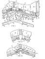
- the reference numeral 1 generally designates an arrangement for hard wiring movable room divider panels 2, and includes wiring raceways 3 connected with room divider panels 2, with the free ends of the raceways disposed in an adjacent, end-to-end relationwhip when the panels are assembled.
- a panel-to-panel wiring connector 4 extends between the ends of adjacent raceways 3, and comprises a protective outer shell with a longitudinally extending interior cavity therethrough communicating the raceways, and shaped to receive wires 5 therein, thereby providing a continuous protective enclosure for the wires.
- the panels 2 are of a conventional design, and include a central panel member 10 having a lower edge 11 and side edges 12 with trim members 13.
- Each panel 10 is supported by a pair of legs 14 which depend from the centre of the panel lower edge 11 at each end of the panel.
- the legs 14 are preferably vertically adjustable, and support the panels 2 a spaced apart distance from the floor, such that wiring raceways 3 may be positioned between the panel lower edge 11 and the supporting floor surface.
- Each panel leg 14 ( Figures 2 to 5) includes an upper, channel-shaped member 15 which is telescopically received in a mating portion of the panel and connects the leg to the panel.
- the leg channels 15 are preferably received in hollow, vertical support columns disposed in the panels 2, such that an aperture or passageway 15' is formed along each side of the panels.
- Detents 16 extend.outwardly of the channel surfaces and provide a stop which abuts the lower edge of the panel 10 and ensures that the panel lower edge 11 is spaced apart a predetermined distance from the supporting floor.
- the panel legs 14 also include a body portion 17, having a flange 18 projecting inwardly along the longitudinal centreline of the raceway 3, and a base 19.
- the leg flange 18 includes an aperture to receive a fastener 20 to connect the wiring raceway 3 to the panel lege 14.
- the leg base 19 includes an adjustable foot or glide 21 threadedly mounted therein for steplessly varying the vertical position of each end of the panels 2.
- a tab portion.22 of the leg base 19 extends inwardly, and is connected with and supports a clip 23 and tray - 24 arrangement which is shaped to receive and retain a. communications cable therein, as described hereinafter in greater detail.
- the wiring arrangement 1 also includes end caps 29 ( Figures 2 to 5) to cover the ends of the space formed between the panel lower edge 11 and the supporting floor at each exposed, outer end of the partition system.
- Each end cap 29 comprises a bracket 30 having one end 30' thereof connected with the leg 14 by fasteners 31.
- the bracket 30 extends inwardly to a medial portion of the side edge 12 of the panel, and thence extends outwardly therefrom to an enlarged cover 32.
- One end cap 29 is connected to each side of the panel leg 14, such that the two covers 32 mate to form a closure having a height and width sufficient to cover the space at the end of the partition between the lower edge 11 of the panel and the floor.
- That portion 33 of'the cover 32 which extends upwardly and downwardly of the bracket 30 is separated from the remainder of the cover by a groove or score line 34 along which cap portion 33 may be severed to facilitate installing communications lines in the tray 24 underneath the wiring raceway 3, as described in greater detail hereinafter.
- the wiring raceways 3 are adapted to extend along the length of the panels 2 and form a protective enclosure for the wires 5 in a manner complying with general electrical building code requirements.
- the raceways 3 are elongate boxes having a substantially rectangular shape, as best illustrated in Figures 1, 2 and 4.
- the raceways comprise upper and lower walls 40 and 41 respectively, with inwardly turned flange segments 42 and 43 along the side edges thereof.
- the upper and lower walls 40 and 41 are interconnected in a spaced apart relationship by fixed side walls 44 to 46 ( Figures 2 and 4) positioned at each end of the raceway and forming an offset portion 47 thereof which is shaped to facilitate the connection of the associated panel leg 14 therewith.
- the side walls 44 to 46 comprise generally U-shaped members with upper and lower flanges 48 thereof overlying the exterior surfaces of the upper and lower walls 40 and 41, and are connected thereto by means such as spot welds 49.
- the fixed side walls 44 to 46 are arranged in a mutually perpendicular fashion, or stepped pattern,so as to form a generally L-shaped space or aperture in which the panel leg 14 is positioned.
- Fixed side wall 45 includes an elongated slot 50 through which a fastener 20 extends and attaches the raceway 3 to leg flange 18, and also includes an electrical ground fastener 51, and an aperture 52 which is adapted to communicate the wiring raceway 3 with the interior 15' of the panel leg 10 and the vertical support post portion of the panel.
- the outer fixed wall 46 is L-shaped, with the outer leg 46' thereof abutting the panel leg 14, and including a pair of spaced apart apertures 53 therein which are aligned with and receive fasteners 31 therein to avoid interference therebetween.
- the raceways 3 include end walls 54 connected with leg 46' on the right-hand side of the raceway and fixed wall 44 on the left-hand side along a groove or score line, such that the end wall may be detached from the raceway to permit adjacent wiring raceways to be electrically interconnected.
- the leg 46' and associated portions of the upper and lower wall 40 and 41 form a shallow U-shaped channel in which the connector 4 is adapted to be telescopically received.
- connector 4 may be inserted between those portions of the upper and lower walls 40 and 41 disposed between the flange 42 and the outer edge of the fixed side wall 44.
- a mounting plate and wireway cover 60 (Figure 1) is connected along both sides of the wiring raceway 3 to close the opening between the upper and lower walls 40 and 41, and to interconnect the upper and lower walls.
- the cover 60 is a channel-shaped structure having a flat face 61 and inwardly extending flanges 62 which are adapted to overlie the exterior surface of the upper and lower walls 40 and 41 so as to form a secure closure for the raceway.
- the plate face 61 also includes a plurality of fastener apertures 63 therethrough which are aligned and mate with threaded apertures in the upper and lower flange members 42 and 43, and are adapted to receive threaded fasteners 59 therethrough to connect the cover 60 with the upper and lower raceway walls 40 and 41.
- the cover 60 also includes an electrical appliance aperture 64 therethrough having recessed end walls 65 with a fastener aperture 66 therein.
- the appliance aperture and wall arrangement 64 and 65 are shaped to mount a standard electrical receptacle 67 ( Figure 12) therein using fasteners 68 threadedly connected in mating cover apertures 66.
- a closure or cover plate.69 is connected with and extends between the recessed end walls 65 by fasteners 68, closing the receptacle opening.
- the cover plate 69 preferably includes a circular knock-out plug 70 positioned centrally therein for purposes to be described hereinafter.
- A.base trim plate 75 is provided for each of the raceways to cover the space between the lower edge of the panel 2 and the supporting floor surface, thereby covering the raceways 3 and communication wire retainers 24, such that all of the wiring is concealed.
- the trim.plate 75 includes an aperture 76 therein which is aligned and shaped to mate with the electrical receptacle 67, and permits the exterior face of the receptacle to extend therethrough.
- An access cover 77 is connected in the trim plate aperture 76 in the event that the associated wireway is not provided with an electrical outlet or other utility.
- the exterior surface of the cover plate is otherwise continuous, and a plurality of tabs 78 extend along the upper and lower edges thereof to form a snap lock engagement with the wiring raceway 3 to retain the same in place.
- the raceway 3 has a symmetrical shape, with oppositely oriented off-set portions 47, and identical upper and. lower halves. In this manner, a single raceway design may be used in a wide variety of different configurations, and may be installed from either side of the panel system.
- the panel-to-panel wiring connector 4 has a split body construction with means for longitudinally opening the protective outer shell, laying the wires 5 into the interior cavity of the connector body, and closing the outer shell about the wires.
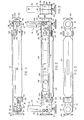
- the connector 4 comprises two U-shaped channel members 84 and 85 which are nested together to form a cavity therebetween in which the wires 5 are received.
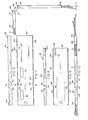
- the first channel member 84 is preferably positioned furthest away from the inside surface of panel 2, and comprises a U-shaped channel with a central web 87 and flanges 88 extending from opposing side edges thereof.
- the flanges 88. are spaced apart a distance substantially commensurate with the distance between the inside surfaces of the upper and lower raceway walls 40 and 41, such that the flanges may be telescopingly inserted therebetween.
- Two pair of V-shaped notches 89 and 90 are provided in the upper and lower flanges 88, and are spaced apart a distance sufficient to form a pair of trapezoidally shaped ears 91 therebetween.
- a pair of apertures 92 are provided in the web 87 adjacent opposing side edges thereof, and are centered at the base of the trapezoidal ears 91.
- a pair of aligned, spaced apart, elongated slots 93 are positioned in the web at a location in alignment with the upper fastener 53 (Figure 2) which connects the end caps 29 to the leg 14.
- the web also includes ends 94 which are bent backwardly and doubled over to form a smooth terminal edge.
- the second channel member 85 is preferably located nearest the inside surface of the panel system, and includes a U-shaped channel having a web 95 and opposing flanges 96 which are spaced apart a distance substantially commensurate with the distance between the inside surfaces of the outside channel flanges 88, such that the same are matingly received therein.
- the interior channel flanges 96 have a width slightly less than that of the outside channel flanges 88, such that when the channel members 84 and 85 are interconnected, the outside channel member flanges 88 and the web 95 of the inside channel are substantially flush.
- the inside channel flanges 96 include two pairs of apertures 97 and 98 therethrough which are vertically aligned, and spaced apart a distance sufficient to form a tab 99 therebetween.
- a connector tongue 100 is formed in web 94 and bent inwardly flush with the free edges of flanges 95 to connect the two connector members 84 and 85.
- the connector tongue includes a slot 101 shaped to receive therein a fastener 102 (Figure 12) which in turn is threaded through a mating aperture 103 ( Figure 7) in the outside channel web 87.
- the outside and inside channel members 84 and 85 are interconnected by inserting the inside channel 85, with flange 96 first, inbetween the flanges 88 of outside channel 84.
- the channel members 84 and 85 are longitudinally aligned until such time as the terminal edges of tabs 99 protrude through mating apertures 92, thereby locking or keying the two channel members in place.
- the trapezoidally shaped ears 91 overlie the tabs 99 and cover the interior flange apertures 97 and 98, such that the connector forms a substantially imperforate shield about the wires.
- the channel members 84 and 85 are preferably constructed of a suitable material such that wiring connector 4 is elastically deformable, and may be manually bent into an angular relationship which is commensurate with the angular relationship between the adjacent room divider panel which the connector is intended to bridge.
- the illustrated channel members 84 and 85 are constructed of a rather low carbon steel, such as 20 gauge cold rolled steel, and may be manually bent in the assembed position, as illustrated in Figures 10 and 11, as a result of the V-notch and aperture arrangement 89-90 and 97-98 in the associated channel flanges.
- outside channel 84 bends at two places, along a pair of parallel lines extending between each pair of V-notches 89 and 90.
- each of the V-notches 89 and 90 is in the nature of 90°, such that the connector may be formed into an angle of greater than 90°.
- the inside channel 85 bends in a similar manner along two lines extending between the associated apertures 97 and 98. Because the outer edge of the trapezoidally shaped ear 91 is substantially equal in width to that of the tabs 99, in this example approximately 6.4 mms (1/4 inch), and the apertures are relatively narrow, in the nature of 3.2 mms (1/8 inch), the connector remains substantially imperforate even when the same is bent into a wide variety of different angular configurations.
- the reference numeral la generally designates another embodiment of the present invention ( Figure 15), wherein the wiring raceway includes a flexible midportion to facilitate wiring curved panels, such as those used to form rounded 90° corners. Since the wiring raceway is otherwise substantially the same as the previously described device, similar parts appearing in Figures 1 to 14 and 15 respectively are represented by the same, corresponding reference numeral, except for the suffic "a" in the numerals of the latter.
- the wiring raceway 3 is truncated at a convenient, predetermined location from each end of the same, and is closed by an end wall 105. Each end wall 105 includes an adapter 106 which attaches the free end of a flexible conduit 107 therewith, such that the conduit communicates with the wiring raceways 3.
- the wireway covers 6"Oa are correspondingly shortened to mate with the associated raceway end.
- the wiring raceways 3 and end caps 29 are preferably installed in new room partition panels at the factory.
- the panels 2 are set into the desired configuration in the room to be partitioned, and are mechanically interconnected.
- an electrician removes one or both of the trim panels 75 from each of the panels to be wired, as well as from those panels disposed between the same and the source of power through which wiring must be run.
- the trim panels 75 are removed by pulling outwardly at the bottom of the panels at extreme ends thereof in the area of the feet or glides 21.
- a wiring raceway 3 is positioned between the legs of the panel and attached thereto by fasteners 20.
- the symmetrical shape of the raceways 3 permits them to be installed from either side of the panel without disassembling the other raceway side. The electrician may then wire the raceways by using a wide variety of different techniques according to the particular circumstances and his personal preference.
- conventional 12-2 or 14-2 wire with an earth may be used, in conjunction with standard 240V/AC duplex outlets, switches, and the like.
- One method for wiring the panels comprises laying the electrical wires 5 loosely around the base of those panels to be wired, as specified by the electrical wiring layout.
- the receptacles 67 are then wired and mounted beginning with those closest to the source of electrical power.
- a connector 4 is provided to shield the wire.
- the electrician initially severs the adjacent raceway end walls 54 along the associated groove by means such as fatiguing the end off with a side-to-side bending motion.
- the electrician then selects a pair of inside and outside channel members 84 and 85, aligns the same by inserting the tabs 99 into the corresponding apertures 92, and then manually bends the channels into an angular relationship which corresponds to that of the adjacently postiioned partitions which the connector is to bridge. If the panels are straight, the connector is not bent. If the.panels intersect at a 90 corner, the connector is bent into a right angle, as illustrated in Figure 11.
- the outside channel 84 is next inserted between the upper and lower walls 40 and 41 of the raceway, such that it fits snugly therein in nested fashion, and fasteners 53 are inserted through connector slots 93 and are engaged in legs 14, thereby securely attaching the ends of the connector to the respective panels.
- the fasteners 53 are conductive so as to establish an electrical earth path between the wireways 3.
- the wires 5 are then shaped to conform to the angle of the outside channel 84 and laid therein, and the inside channel 85 is then placed thereover, with tabs 99 located in apertures 92, and connected with the outside channel 84 by fastener 102, such that the wires are safely received in and shielded by the connector.
- Fastener 102 is also preferably conductive to ensure a continuous electrical earth path through the wiring raceways 3.
- Receptacles 67 are installed in the raceways -3 by drawing a loop or free end of the wire through the cover aperture 64, preferably while the cover 60 is disassembled from the raceway.
- the wires 5 are then prepared in a.conventional fashion by stripping the insulation from the free ends, and connecting them to the receptacle 67.
- the ground wire is connected to the fastener 51 to ensure proper electrical earthing for the panel system.
- the receptacle 67 is connected to the cover 60 by fastener 68, and wireway cover 60 is in turn connected to the wiring raceway 3 by fasteners 59, such that the wiring raceways 3 in combination with the connectors 4 form a continuous shield for the wiring 5.
- the knock-out plug 70 is removed from the receptacle cover plate 69, and an appropriate socket is physically connected therewith (see, for example, Figure 16), and the wires are run through the raceway.
- the cover plate is then reconnected with the wireway cover 60.
- wires 5 are to be directed to the ceiling or floor, the wires are threaded through the raceway aperture 52 at a selected end of the raceway, and directed upwardly or downwardly through the vertical passageway 15'.
- communications lines 112 such as intercom and telephone wires, are connected with the panels 2 in a manner which completely isolates them from the electrical wires 5, as is required by strict building codes.
- the lower portion 33 of the cap is severed therefrom along groove 34 to form an aperture into which the communication line can be inserted.
- the line 112 is directed between clip 23 and the upper surface of the tray 24, and is supported along its medial portion on tray 24. Those end caps 29 which are required at the exposed, free ends of the panels may then be replaced.
- the base trim panels 75 are then snapped onto the wiring raceways. At those locations in which a receptacle or power inlet is located, the plug member 77 is removed, such that the electrical appliance may extend therethrough for easy access.
- the split body construction of the connectors 4, in conjunction with the wiring raceways 3, provides an arrangement for efficiently hard wiring the panel system without pre-wired, flexible conduit connectors and/or a conventional conduit type of installation. Because the connectors 4 are manually bendable and have an uncomplicated design, the panels may be completely wired with the use of just a few, simple hand tools, such as pliers and screwdrivers.
Landscapes
- Engineering & Computer Science (AREA)
- Architecture (AREA)
- Civil Engineering (AREA)
- Structural Engineering (AREA)
- Installation Of Indoor Wiring (AREA)
Applications Claiming Priority (2)
| Application Number | Priority Date | Filing Date | Title |
|---|---|---|---|
| US91789 | 1979-11-06 | ||
| US06/091,789 US4308418A (en) | 1979-11-06 | 1979-11-06 | Arrangement for hard wiring movable room divider panels |
Publications (1)
| Publication Number | Publication Date |
|---|---|
| EP0029676A1 true EP0029676A1 (fr) | 1981-06-03 |
Family
ID=22229662
Family Applications (1)
| Application Number | Title | Priority Date | Filing Date |
|---|---|---|---|
| EP80303972A Withdrawn EP0029676A1 (fr) | 1979-11-06 | 1980-11-06 | Connecteur pour l'interconnexion électrique d'un système à panneaux et un système à panneaux incorporant le connecteur |
Country Status (4)
| Country | Link |
|---|---|
| US (1) | US4308418A (fr) |
| EP (1) | EP0029676A1 (fr) |
| JP (1) | JPS5667104A (fr) |
| CA (1) | CA1140314A (fr) |
Cited By (2)
| Publication number | Priority date | Publication date | Assignee | Title |
|---|---|---|---|---|
| WO1992019825A1 (fr) * | 1991-04-29 | 1992-11-12 | Teknion Furniture Systems | Panneau pour bureaux permettant de poser directement des cables de telecommunications |
| GB2289903A (en) * | 1994-05-12 | 1995-12-06 | Wu Ming Hsin | Conduit connecting mechanism for a screen panel |
Families Citing this family (37)
| Publication number | Priority date | Publication date | Assignee | Title |
|---|---|---|---|---|
| FR2508524A1 (fr) * | 1981-06-25 | 1982-12-31 | Mors Jean Bouchon Entr Elect | Ensemble modulaire de construction d'un emplacement d'exposition |
| JPS58156908U (ja) * | 1982-04-15 | 1983-10-20 | 株式会社稲葉製作所 | パ−テイシヨンにおける余剰コ−ドの収納装置 |
| JPS59192508U (ja) * | 1983-06-08 | 1984-12-20 | 株式会社 伊藤喜工作所 | 間仕切壁における設備盤装置 |
| US4703985A (en) * | 1985-02-07 | 1987-11-03 | Haworth, Inc. | Raceway for curved wall panel |
| US4800696A (en) * | 1986-12-17 | 1989-01-31 | Amp Incorporated | Premise wiring system for frame structures |
| US4808768A (en) * | 1987-02-05 | 1989-02-28 | Richard E. Caragher | Utility routing system for modular panels |
| US4874322A (en) * | 1987-09-28 | 1989-10-17 | Amp Incorporated | Surface applied wiring apparatus |
| US4952163A (en) * | 1988-09-26 | 1990-08-28 | Amp Incorporated | Outlet for surface accessible wiring |
| US4932181A (en) * | 1988-11-23 | 1990-06-12 | The Shaw-Walker Company | Base assembly for an open office partition panel |
| US5152698A (en) * | 1989-02-07 | 1992-10-06 | Steelcase Inc. | Floor track system for office furniture and the like |
| US5092786A (en) * | 1989-02-21 | 1992-03-03 | Steelcase Inc. | Modular powerway for office furniture and the like |
| US5158472A (en) * | 1989-02-21 | 1992-10-27 | Steelcase Inc. | Modular powerway for office furniture and the like |
| US5209035A (en) | 1991-01-10 | 1993-05-11 | Steelcase Inc. | Utility panel system |
| US5252086A (en) * | 1992-05-28 | 1993-10-12 | Steelcase Inc. | Modular powerway with selectable receptacle |
| US5277609A (en) * | 1992-05-28 | 1994-01-11 | Steelcase Inc. | Modular powderway for partition panels and the like (C-39) |
| US5451714A (en) * | 1993-03-11 | 1995-09-19 | Spectranet International | Telephone and data signal distribution system and raceway and panel associated therewith |
| US5886295A (en) * | 1997-07-18 | 1999-03-23 | Steelcase Inc. | Modular utility distribution mounting system |
| US5942724A (en) * | 1997-09-23 | 1999-08-24 | The Wiremold Company | Wire containment system for mounting on a wall structure |
| US5998732A (en) * | 1998-01-13 | 1999-12-07 | Panduit Corp. | Raceway outlet station |
| US6235988B1 (en) * | 1999-05-28 | 2001-05-22 | Pent Assemblies, Inc. | Wall panel assembly |
| US6291769B1 (en) * | 1999-12-28 | 2001-09-18 | Mono-Systems, Inc. | Device plate for divided cable raceway |
| US6344611B2 (en) | 2000-03-08 | 2002-02-05 | Hubbell Incorporated | Raceway fitting with or without fitting base |
| CA2339604C (fr) * | 2000-03-08 | 2007-09-04 | Hubbell Incorporated | Accessoire de canalisation de cables avec ou sans raccord a embase |
| US6344610B1 (en) * | 2000-03-23 | 2002-02-05 | Pent Products, Inc. | Rigid electrical conduct with pass-through cut-out for use in a modular wall panel |
| US7569775B2 (en) * | 2005-01-13 | 2009-08-04 | The Wiremold Company | T-shaped raceway base scoring system (with slots) |
| US7262371B2 (en) * | 2005-01-13 | 2007-08-28 | The Wiremold Company | Modular raceway with base and integral divider |
| US7741568B2 (en) * | 2005-01-13 | 2010-06-22 | The Wiremold Company | Downward facing receptacle assembly for cable raceway |
| US7388163B2 (en) * | 2005-08-23 | 2008-06-17 | Panduit Corp. | Metal raceway system |
| US7926231B2 (en) * | 2005-10-19 | 2011-04-19 | Group Dekko, Inc. | Apparatus and method of routing cabling around leveler legs in a thin modular office panel |
| US8910435B2 (en) | 2008-05-27 | 2014-12-16 | Steelcase Inc. | Partition assembly |
| AU2010279668B2 (en) * | 2009-08-06 | 2014-08-07 | Corning Research & Development Corporation | System and method for providing final drop in a living unit in a building |
| US20120192505A1 (en) * | 2011-01-31 | 2012-08-02 | Alfred Lawrence Michaelsen | Wood construction members and methods |
| US11259637B2 (en) | 2015-04-13 | 2022-03-01 | Steelcase Inc. | Seating arrangement |
| US10194750B2 (en) | 2015-04-13 | 2019-02-05 | Steelcase Inc. | Seating arrangement |
| US10966527B2 (en) | 2017-06-09 | 2021-04-06 | Steelcase Inc. | Seating arrangement and method of construction |
| EP3984413A1 (fr) | 2015-04-13 | 2022-04-20 | Steelcase Inc. | Agencement de siège |
| US10181675B1 (en) * | 2017-12-19 | 2019-01-15 | Kenneth E. Anderson | Electrical outlet plug strip |
Citations (6)
| Publication number | Priority date | Publication date | Assignee | Title |
|---|---|---|---|---|
| FR1305181A (fr) * | 1961-11-10 | 1962-09-28 | Plinthe électrique | |
| DE2458311A1 (de) * | 1974-12-10 | 1976-06-16 | Friedhelm H Timpert | Sockelleiste zur aufnahme von wasserfuehrenden rohrleitungen oder elektrischen kabeln |
| FR2324827A1 (fr) * | 1975-09-22 | 1977-04-15 | Haworth Mfg Inc | Panneau prefabrique precable |
| US4096349A (en) * | 1977-04-04 | 1978-06-20 | Lightolier Incorporated | Flexible connector for track lighting systems |
| FR2400786A1 (fr) * | 1977-08-18 | 1979-03-16 | Miller Herman Inc | Dispositif de distribution de courant electrique pour des postes de travail dans un systeme de cloisonnement |
| BE875223A (fr) * | 1978-05-26 | 1979-07-16 | Steelcase Inc | Systeme de panneaux pour cloison mobile |
Family Cites Families (11)
| Publication number | Priority date | Publication date | Assignee | Title |
|---|---|---|---|---|
| US2066242A (en) * | 1934-07-14 | 1936-12-29 | Bryant Electric Co | Conduit construction |
| US2321304A (en) * | 1939-10-16 | 1943-06-08 | United States Gypsum Co | Wall construction |
| US2790653A (en) * | 1954-07-15 | 1957-04-30 | Wiremold Co | Elbow connection for surface wiring conduits |
| US3529389A (en) * | 1968-09-30 | 1970-09-22 | Comstruct Inc | Modular building wall structure with electrical raceway means |
| US3619477A (en) * | 1970-01-26 | 1971-11-09 | Harry R Rasmussen | Escutcheon |
| US3841042A (en) * | 1973-03-13 | 1974-10-15 | Tiffany Industries | Panel locking devices |
| CA1011915A (en) * | 1974-11-20 | 1977-06-14 | Precision Mfg Inc | Divider screen assembly |
| US3990204A (en) * | 1975-09-22 | 1976-11-09 | Haworth Mfg., Inc. | Alignment system for wall panels |
| US4017137A (en) * | 1976-01-16 | 1977-04-12 | The Wiremold Company | Electrical raceway and receptacle assemblies |
| US4133153A (en) * | 1977-03-21 | 1979-01-09 | Gf Business Equipment, Inc. | Partition raceway |
| US4135775A (en) * | 1977-06-20 | 1979-01-23 | Steelcase Inc. | Movable divider panels with electrical wiring |
-
1979
- 1979-11-06 US US06/091,789 patent/US4308418A/en not_active Expired - Lifetime
-
1980
- 1980-09-30 CA CA000361279A patent/CA1140314A/fr not_active Expired
- 1980-10-20 JP JP14582180A patent/JPS5667104A/ja active Pending
- 1980-11-06 EP EP80303972A patent/EP0029676A1/fr not_active Withdrawn
Patent Citations (9)
| Publication number | Priority date | Publication date | Assignee | Title |
|---|---|---|---|---|
| FR1305181A (fr) * | 1961-11-10 | 1962-09-28 | Plinthe électrique | |
| DE2458311A1 (de) * | 1974-12-10 | 1976-06-16 | Friedhelm H Timpert | Sockelleiste zur aufnahme von wasserfuehrenden rohrleitungen oder elektrischen kabeln |
| FR2324827A1 (fr) * | 1975-09-22 | 1977-04-15 | Haworth Mfg Inc | Panneau prefabrique precable |
| US4060294A (en) * | 1975-09-22 | 1977-11-29 | Haworth Mfg., Inc. | Wall panel with prewired power system |
| US4096349A (en) * | 1977-04-04 | 1978-06-20 | Lightolier Incorporated | Flexible connector for track lighting systems |
| FR2400786A1 (fr) * | 1977-08-18 | 1979-03-16 | Miller Herman Inc | Dispositif de distribution de courant electrique pour des postes de travail dans un systeme de cloisonnement |
| GB2004132A (en) * | 1977-08-18 | 1979-03-21 | Miller Herman Inc | >Electric energy supply system for a space divider system |
| BE875223A (fr) * | 1978-05-26 | 1979-07-16 | Steelcase Inc | Systeme de panneaux pour cloison mobile |
| GB2021876A (en) * | 1978-05-26 | 1979-12-05 | Steelcase Inc | Room divider panel assemblies |
Cited By (3)
| Publication number | Priority date | Publication date | Assignee | Title |
|---|---|---|---|---|
| WO1992019825A1 (fr) * | 1991-04-29 | 1992-11-12 | Teknion Furniture Systems | Panneau pour bureaux permettant de poser directement des cables de telecommunications |
| GB2289903A (en) * | 1994-05-12 | 1995-12-06 | Wu Ming Hsin | Conduit connecting mechanism for a screen panel |
| GB2289903B (en) * | 1994-05-12 | 1997-08-20 | Wu Ming Hsin | Conduit connecting mechanism for a screen panel |
Also Published As
| Publication number | Publication date |
|---|---|
| JPS5667104A (en) | 1981-06-06 |
| CA1140314A (fr) | 1983-02-01 |
| US4308418A (en) | 1981-12-29 |
Similar Documents
| Publication | Publication Date | Title |
|---|---|---|
| US4308418A (en) | Arrangement for hard wiring movable room divider panels | |
| CA1133617A (fr) | Systeme de cablage pour tableaux | |
| US4270020A (en) | Partition wiring system | |
| US5913787A (en) | Communications conduit connector mounting device | |
| US6158180A (en) | Mounting device for communications conduit connector | |
| US7456366B2 (en) | Modular raceway with base and integral divider | |
| US5285009A (en) | Electrical floor box | |
| CA1133618A (fr) | Systeme de cablage de tableaux | |
| US7826202B2 (en) | Modular electrical distribution system for a building | |
| US5673522A (en) | Junction box forlow profile raised panel flooring | |
| US8093510B2 (en) | Downward facing receptacle assembly for cable raceway | |
| US4874322A (en) | Surface applied wiring apparatus | |
| US5396027A (en) | Strip electrical system | |
| US8172588B2 (en) | Modular electrical distribution system for a building | |
| US7183504B2 (en) | Electrical floor access module system | |
| US4627684A (en) | Housing for electrical connectors | |
| EP1839380B1 (fr) | Chemin de câbles modulaire avec base et diviseur intégral | |
| CA1199379A (fr) | Jupe de distribution d'energie electrique et d'entites similaires dans les installations privees | |
| JPH0287920A (ja) | カーペット下の電力用配線システムおよびアダプタ | |
| US6730844B2 (en) | Dual-purpose wiring device and method of wiring | |
| CA2519168C (fr) | Dispositif de pose de connecteur pour conduit de communications | |
| CA1133619A (fr) | Systeme de cablage pour cloison mobile | |
| CA2232335C (fr) | Dispositif de montage pour connecteur de conduit de cables de transmission |
Legal Events
| Date | Code | Title | Description |
|---|---|---|---|
| PUAI | Public reference made under article 153(3) epc to a published international application that has entered the european phase |
Free format text: ORIGINAL CODE: 0009012 |
|
| AK | Designated contracting states |
Designated state(s): DE FR GB |
|
| 17P | Request for examination filed |
Effective date: 19810629 |
|
| STAA | Information on the status of an ep patent application or granted ep patent |
Free format text: STATUS: THE APPLICATION IS DEEMED TO BE WITHDRAWN |
|
| 18D | Application deemed to be withdrawn |
Effective date: 19831117 |
|
| RIN1 | Information on inventor provided before grant (corrected) |
Inventor name: SPEET, LARRY ALBERT Inventor name: VAN KUIK, DIRK JACOBUS |