EP0029678B1 - Récupération d'hydrocarbures en C2 à partir d'un courant de tête d'un déméthaniseur - Google Patents
Récupération d'hydrocarbures en C2 à partir d'un courant de tête d'un déméthaniseur Download PDFInfo
- Publication number
- EP0029678B1 EP0029678B1 EP80304004A EP80304004A EP0029678B1 EP 0029678 B1 EP0029678 B1 EP 0029678B1 EP 80304004 A EP80304004 A EP 80304004A EP 80304004 A EP80304004 A EP 80304004A EP 0029678 B1 EP0029678 B1 EP 0029678B1
- Authority
- EP
- European Patent Office
- Prior art keywords
- stream
- hydrocarbons
- liquid
- vapor
- enriched
- Prior art date
- Legal status (The legal status is an assumption and is not a legal conclusion. Google has not performed a legal analysis and makes no representation as to the accuracy of the status listed.)
- Expired
Links
- 238000011084 recovery Methods 0.000 title claims description 41
- 229930195733 hydrocarbon Natural products 0.000 title claims description 39
- 150000002430 hydrocarbons Chemical class 0.000 title claims description 39
- 239000007788 liquid Substances 0.000 claims description 54
- VGGSQFUCUMXWEO-UHFFFAOYSA-N Ethene Chemical compound C=C VGGSQFUCUMXWEO-UHFFFAOYSA-N 0.000 claims description 38
- 239000005977 Ethylene Substances 0.000 claims description 38
- VNWKTOKETHGBQD-UHFFFAOYSA-N methane Chemical compound C VNWKTOKETHGBQD-UHFFFAOYSA-N 0.000 claims description 30
- 238000010992 reflux Methods 0.000 claims description 30
- 239000001257 hydrogen Substances 0.000 claims description 17
- 229910052739 hydrogen Inorganic materials 0.000 claims description 17
- 238000000034 method Methods 0.000 claims description 16
- 238000005057 refrigeration Methods 0.000 claims description 14
- 238000009833 condensation Methods 0.000 claims description 11
- 230000005494 condensation Effects 0.000 claims description 11
- 239000003507 refrigerant Substances 0.000 claims description 10
- 239000000203 mixture Substances 0.000 claims description 9
- 239000004215 Carbon black (E152) Substances 0.000 claims description 6
- 230000003993 interaction Effects 0.000 claims description 3
- 239000012530 fluid Substances 0.000 claims description 2
- 125000004435 hydrogen atom Chemical class [H]* 0.000 claims 1
- 239000007789 gas Substances 0.000 description 19
- UFHFLCQGNIYNRP-UHFFFAOYSA-N Hydrogen Chemical compound [H][H] UFHFLCQGNIYNRP-UHFFFAOYSA-N 0.000 description 13
- OTMSDBZUPAUEDD-UHFFFAOYSA-N Ethane Chemical compound CC OTMSDBZUPAUEDD-UHFFFAOYSA-N 0.000 description 8
- 238000001816 cooling Methods 0.000 description 5
- 238000000926 separation method Methods 0.000 description 5
- IJGRMHOSHXDMSA-UHFFFAOYSA-N Atomic nitrogen Chemical compound N#N IJGRMHOSHXDMSA-UHFFFAOYSA-N 0.000 description 4
- ATUOYWHBWRKTHZ-UHFFFAOYSA-N Propane Chemical compound CCC ATUOYWHBWRKTHZ-UHFFFAOYSA-N 0.000 description 4
- 238000009835 boiling Methods 0.000 description 4
- 238000010586 diagram Methods 0.000 description 3
- 150000002431 hydrogen Chemical class 0.000 description 3
- 239000012263 liquid product Substances 0.000 description 3
- 239000000047 product Substances 0.000 description 3
- QGZKDVFQNNGYKY-UHFFFAOYSA-N Ammonia Chemical compound N QGZKDVFQNNGYKY-UHFFFAOYSA-N 0.000 description 2
- XKRFYHLGVUSROY-UHFFFAOYSA-N Argon Chemical compound [Ar] XKRFYHLGVUSROY-UHFFFAOYSA-N 0.000 description 2
- 238000004821 distillation Methods 0.000 description 2
- 239000008246 gaseous mixture Substances 0.000 description 2
- 229910052757 nitrogen Inorganic materials 0.000 description 2
- 239000001294 propane Substances 0.000 description 2
- OKTJSMMVPCPJKN-UHFFFAOYSA-N Carbon Chemical compound [C] OKTJSMMVPCPJKN-UHFFFAOYSA-N 0.000 description 1
- UGFAIRIUMAVXCW-UHFFFAOYSA-N Carbon monoxide Chemical compound [O+]#[C-] UGFAIRIUMAVXCW-UHFFFAOYSA-N 0.000 description 1
- HSFWRNGVRCDJHI-UHFFFAOYSA-N alpha-acetylene Natural products C#C HSFWRNGVRCDJHI-UHFFFAOYSA-N 0.000 description 1
- 229910021529 ammonia Inorganic materials 0.000 description 1
- 229910052786 argon Inorganic materials 0.000 description 1
- 229910052799 carbon Inorganic materials 0.000 description 1
- 229910002091 carbon monoxide Inorganic materials 0.000 description 1
- 230000006835 compression Effects 0.000 description 1
- 238000007906 compression Methods 0.000 description 1
- 230000000694 effects Effects 0.000 description 1
- 230000002708 enhancing effect Effects 0.000 description 1
- 125000002534 ethynyl group Chemical group [H]C#C* 0.000 description 1
- 230000002349 favourable effect Effects 0.000 description 1
- 239000000463 material Substances 0.000 description 1
- 239000003345 natural gas Substances 0.000 description 1
- QQONPFPTGQHPMA-UHFFFAOYSA-N propylene Natural products CC=C QQONPFPTGQHPMA-UHFFFAOYSA-N 0.000 description 1
- 125000004805 propylene group Chemical group [H]C([H])([H])C([H])([*:1])C([H])([H])[*:2] 0.000 description 1
- 238000010926 purge Methods 0.000 description 1
Images

Classifications
-
- F—MECHANICAL ENGINEERING; LIGHTING; HEATING; WEAPONS; BLASTING
- F25—REFRIGERATION OR COOLING; COMBINED HEATING AND REFRIGERATION SYSTEMS; HEAT PUMP SYSTEMS; MANUFACTURE OR STORAGE OF ICE; LIQUEFACTION SOLIDIFICATION OF GASES
- F25J—LIQUEFACTION, SOLIDIFICATION OR SEPARATION OF GASES OR GASEOUS OR LIQUEFIED GASEOUS MIXTURES BY PRESSURE AND COLD TREATMENT OR BY BRINGING THEM INTO THE SUPERCRITICAL STATE
- F25J3/00—Processes or apparatus for separating the constituents of gaseous or liquefied gaseous mixtures involving the use of liquefaction or solidification
- F25J3/02—Processes or apparatus for separating the constituents of gaseous or liquefied gaseous mixtures involving the use of liquefaction or solidification by rectification, i.e. by continuous interchange of heat and material between a vapour stream and a liquid stream
- F25J3/0228—Processes or apparatus for separating the constituents of gaseous or liquefied gaseous mixtures involving the use of liquefaction or solidification by rectification, i.e. by continuous interchange of heat and material between a vapour stream and a liquid stream characterised by the separated product stream
- F25J3/0252—Processes or apparatus for separating the constituents of gaseous or liquefied gaseous mixtures involving the use of liquefaction or solidification by rectification, i.e. by continuous interchange of heat and material between a vapour stream and a liquid stream characterised by the separated product stream separation of hydrogen
-
- B—PERFORMING OPERATIONS; TRANSPORTING
- B01—PHYSICAL OR CHEMICAL PROCESSES OR APPARATUS IN GENERAL
- B01D—SEPARATION
- B01D3/00—Distillation or related exchange processes in which liquids are contacted with gaseous media, e.g. stripping
- B01D3/14—Fractional distillation or use of a fractionation or rectification column
-
- C—CHEMISTRY; METALLURGY
- C07—ORGANIC CHEMISTRY
- C07C—ACYCLIC OR CARBOCYCLIC COMPOUNDS
- C07C7/00—Purification; Separation; Use of additives
- C07C7/04—Purification; Separation; Use of additives by distillation
-
- F—MECHANICAL ENGINEERING; LIGHTING; HEATING; WEAPONS; BLASTING
- F25—REFRIGERATION OR COOLING; COMBINED HEATING AND REFRIGERATION SYSTEMS; HEAT PUMP SYSTEMS; MANUFACTURE OR STORAGE OF ICE; LIQUEFACTION SOLIDIFICATION OF GASES
- F25J—LIQUEFACTION, SOLIDIFICATION OR SEPARATION OF GASES OR GASEOUS OR LIQUEFIED GASEOUS MIXTURES BY PRESSURE AND COLD TREATMENT OR BY BRINGING THEM INTO THE SUPERCRITICAL STATE
- F25J3/00—Processes or apparatus for separating the constituents of gaseous or liquefied gaseous mixtures involving the use of liquefaction or solidification
- F25J3/02—Processes or apparatus for separating the constituents of gaseous or liquefied gaseous mixtures involving the use of liquefaction or solidification by rectification, i.e. by continuous interchange of heat and material between a vapour stream and a liquid stream
- F25J3/0204—Processes or apparatus for separating the constituents of gaseous or liquefied gaseous mixtures involving the use of liquefaction or solidification by rectification, i.e. by continuous interchange of heat and material between a vapour stream and a liquid stream characterised by the feed stream
- F25J3/0219—Refinery gas, cracking gas, coke oven gas, gaseous mixtures containing aliphatic unsaturated CnHm or gaseous mixtures of undefined nature
-
- F—MECHANICAL ENGINEERING; LIGHTING; HEATING; WEAPONS; BLASTING
- F25—REFRIGERATION OR COOLING; COMBINED HEATING AND REFRIGERATION SYSTEMS; HEAT PUMP SYSTEMS; MANUFACTURE OR STORAGE OF ICE; LIQUEFACTION SOLIDIFICATION OF GASES
- F25J—LIQUEFACTION, SOLIDIFICATION OR SEPARATION OF GASES OR GASEOUS OR LIQUEFIED GASEOUS MIXTURES BY PRESSURE AND COLD TREATMENT OR BY BRINGING THEM INTO THE SUPERCRITICAL STATE
- F25J3/00—Processes or apparatus for separating the constituents of gaseous or liquefied gaseous mixtures involving the use of liquefaction or solidification
- F25J3/02—Processes or apparatus for separating the constituents of gaseous or liquefied gaseous mixtures involving the use of liquefaction or solidification by rectification, i.e. by continuous interchange of heat and material between a vapour stream and a liquid stream
- F25J3/0228—Processes or apparatus for separating the constituents of gaseous or liquefied gaseous mixtures involving the use of liquefaction or solidification by rectification, i.e. by continuous interchange of heat and material between a vapour stream and a liquid stream characterised by the separated product stream
- F25J3/0233—Processes or apparatus for separating the constituents of gaseous or liquefied gaseous mixtures involving the use of liquefaction or solidification by rectification, i.e. by continuous interchange of heat and material between a vapour stream and a liquid stream characterised by the separated product stream separation of CnHm with 1 carbon atom or more
-
- F—MECHANICAL ENGINEERING; LIGHTING; HEATING; WEAPONS; BLASTING
- F25—REFRIGERATION OR COOLING; COMBINED HEATING AND REFRIGERATION SYSTEMS; HEAT PUMP SYSTEMS; MANUFACTURE OR STORAGE OF ICE; LIQUEFACTION SOLIDIFICATION OF GASES
- F25J—LIQUEFACTION, SOLIDIFICATION OR SEPARATION OF GASES OR GASEOUS OR LIQUEFIED GASEOUS MIXTURES BY PRESSURE AND COLD TREATMENT OR BY BRINGING THEM INTO THE SUPERCRITICAL STATE
- F25J3/00—Processes or apparatus for separating the constituents of gaseous or liquefied gaseous mixtures involving the use of liquefaction or solidification
- F25J3/02—Processes or apparatus for separating the constituents of gaseous or liquefied gaseous mixtures involving the use of liquefaction or solidification by rectification, i.e. by continuous interchange of heat and material between a vapour stream and a liquid stream
- F25J3/0228—Processes or apparatus for separating the constituents of gaseous or liquefied gaseous mixtures involving the use of liquefaction or solidification by rectification, i.e. by continuous interchange of heat and material between a vapour stream and a liquid stream characterised by the separated product stream
- F25J3/0238—Processes or apparatus for separating the constituents of gaseous or liquefied gaseous mixtures involving the use of liquefaction or solidification by rectification, i.e. by continuous interchange of heat and material between a vapour stream and a liquid stream characterised by the separated product stream separation of CnHm with 2 carbon atoms or more
-
- F—MECHANICAL ENGINEERING; LIGHTING; HEATING; WEAPONS; BLASTING
- F25—REFRIGERATION OR COOLING; COMBINED HEATING AND REFRIGERATION SYSTEMS; HEAT PUMP SYSTEMS; MANUFACTURE OR STORAGE OF ICE; LIQUEFACTION SOLIDIFICATION OF GASES
- F25J—LIQUEFACTION, SOLIDIFICATION OR SEPARATION OF GASES OR GASEOUS OR LIQUEFIED GASEOUS MIXTURES BY PRESSURE AND COLD TREATMENT OR BY BRINGING THEM INTO THE SUPERCRITICAL STATE
- F25J2200/00—Processes or apparatus using separation by rectification
- F25J2200/80—Processes or apparatus using separation by rectification using integrated mass and heat exchange, i.e. non-adiabatic rectification in a reflux exchanger or dephlegmator
-
- F—MECHANICAL ENGINEERING; LIGHTING; HEATING; WEAPONS; BLASTING
- F25—REFRIGERATION OR COOLING; COMBINED HEATING AND REFRIGERATION SYSTEMS; HEAT PUMP SYSTEMS; MANUFACTURE OR STORAGE OF ICE; LIQUEFACTION SOLIDIFICATION OF GASES
- F25J—LIQUEFACTION, SOLIDIFICATION OR SEPARATION OF GASES OR GASEOUS OR LIQUEFIED GASEOUS MIXTURES BY PRESSURE AND COLD TREATMENT OR BY BRINGING THEM INTO THE SUPERCRITICAL STATE
- F25J2210/00—Processes characterised by the type or other details of the feed stream
- F25J2210/12—Refinery or petrochemical off-gas
-
- F—MECHANICAL ENGINEERING; LIGHTING; HEATING; WEAPONS; BLASTING
- F25—REFRIGERATION OR COOLING; COMBINED HEATING AND REFRIGERATION SYSTEMS; HEAT PUMP SYSTEMS; MANUFACTURE OR STORAGE OF ICE; LIQUEFACTION SOLIDIFICATION OF GASES
- F25J—LIQUEFACTION, SOLIDIFICATION OR SEPARATION OF GASES OR GASEOUS OR LIQUEFIED GASEOUS MIXTURES BY PRESSURE AND COLD TREATMENT OR BY BRINGING THEM INTO THE SUPERCRITICAL STATE
- F25J2245/00—Processes or apparatus involving steps for recycling of process streams
- F25J2245/02—Recycle of a stream in general, e.g. a by-pass stream
-
- F—MECHANICAL ENGINEERING; LIGHTING; HEATING; WEAPONS; BLASTING
- F25—REFRIGERATION OR COOLING; COMBINED HEATING AND REFRIGERATION SYSTEMS; HEAT PUMP SYSTEMS; MANUFACTURE OR STORAGE OF ICE; LIQUEFACTION SOLIDIFICATION OF GASES
- F25J—LIQUEFACTION, SOLIDIFICATION OR SEPARATION OF GASES OR GASEOUS OR LIQUEFIED GASEOUS MIXTURES BY PRESSURE AND COLD TREATMENT OR BY BRINGING THEM INTO THE SUPERCRITICAL STATE
- F25J2270/00—Refrigeration techniques used
- F25J2270/04—Internal refrigeration with work-producing gas expansion loop
Definitions
- the present invention relates to low temperature separation of gaseous mixtures and is particularly concerned with enhancing recovery of ethylene and/or ethane from a mixture of hydrocarbons and low boiling gases containing the same.
- Demethanizer columns commonly employ low pressure ethane or ethylene as refrigerant to condense the overhead reflux.
- Joule-Thompson (J-T) expansion refrigeration obtained from the overhead vapor product is utilized to provide auxiliary reflux, by partial condensation of the vapor leaving the main reflux condenser.
- J-T Joule-Thompson
- auxiliary partial condensation permits recovery of approximately 10% of the ethylene remaining in the vapor from the main condenser.
- Such processes are relatively inefficient in terms of the amount of ethylene recovered (10%) due to the extremely large amount of methane which must be condensed in order to recover the residual ethylene.
- Dephlegmators have been employed in the separation of binary gas mixtures, particularly where the components have widely separated boiling points.
- the feed gas is introduced into a dephlegmator where it is cooled to form a condensate stream containing the major portion of the C 2 + hydrocarbons.
- the condensate stream, together with prior condensed material from the feed gas is passed to a demethanizer column.
- the uncondensed portion of the overhead vapor from the demethanizer column reflux condenser is utilized as one of the refrigerant streams in the dephlegmator.
- Dephlegmators have been used for condensation and recovery of methane from ammonia plant purge gas or other industrial mixtures which contain hydrogen and one or more other low-boiling gases such as nitrogen and/or argon.
- a method of obtaining enhanced recovery of C 2 hydrocarbons from the vapor overhead of a demethanizer column charged with a composition containing C 2 hydrocarbons in admixture with hydrogen, methane and C 3 + hydrocarbons which comprises the steps of condensing a portion of said overhead vapors and returning the condensate as main reflux to the demethanizer column, characterized in that said method further comprises the steps of introducing the uncondensed vapors as a stream containing residua!
- the C 2 hydrocarbon enriched liquid stream withdrawn from said dephlegmation zone is returned directly to said demethanizer column as auxiliary reflux for recovery of the C 2 hydrocarbons contained therein in the liquid bottoms withdrawn from said demethanizer column.
- the pressure reduction of the upwardly flowing vapor may be effected, for example, by passage through a Joule-Thompson expansion valve or, more advantageously, by work expansion.
- an expansion engine can provide sufficient refrigeration to the dephlegmator for the ethylene recovery to be increased to 90% or more.
- Such enhanced recovery of ethylene results from the rectification taking place in the dephlegmator. Since less of the methane and lighter components are condensed in the dephlegmator system than in the case of systems employing partial condensors, more of the available refrigeration is utilized to condense ethylene. The liquid stream produced in the dephlegmator is therefore more concentrated in ethylene.
- the vapour stream first introduced into said dephlegmation zone comprises up to about 2% ethylene, more than 85% of which ethylene is recovered in the C 2 enriched liquid stream returned to said demethanizer column.
- the vapor stream first introduced into said dephlegmation zone comprises up to about 2% ethylene, more than 60% of which ethylene is recovered in the C 2 enriched liquid stream returned to said demethanizer column.
- the uncondensed vapor stream is initially introduced into said dephlegmation zone at a pressure of 28 to 42 kg/cm 2 absolute and at a temperature of 170 to 195°K.
- the C 2 enriched liquid stream is withdrawn from said dephlegmation zone at a temperature in the range of 168 to 194°K.
- the upwardly flowing vapors from said dephlegmation zone are further partially condensed and separated into a H 2 enriched vapor stream and a C 1 enriched liquid stream prior to pressure reduction of at least one of said streams for refrigeration supply to the dephlegmation zone.
- the upwardly flowing vapors from said dephlegmation zone are partially condensed in a heat exchanger zone and the resulting partially condensed vapor stream is separated into the H 2 enriched vapor stream and the C 1 enriched liquid stream.
- feed stream is introduced by line 10 into demethanizer column 11.
- a typical feed stream for example, will contain:
- the feed stream which will ordinarily contain mixed vapor and liquid components, is preferably introduced into the demethanizer column at a pressure in the range of about 3 1 - 41 kg/cm 2 , 30 to 40 atmospheres and at a temperature in the range of 195 to 230°K.
- the vapor overhead fraction, discharged from the demethanizer through line 13, is composed chiefly of hydrogen and methane but will usually contain about 2 to 5% of the ethane initially present in the demethanizer feed stream and about 15 to 20% of the original ethylene content thereof.
- the vapor fraction in line 13 is cooled by indirect heat exchange with refrigerant, such as ethylene, in the main reflux condenser 15 to a temperature of about 170 to 195°K and introduced into a phase separator 16. Separated liquid is returned to the demethanizer column as reflux via line 17.
- refrigerant such as ethylene
- the vapor fraction from the phase separator 16 is withdrawn by line 18 and passed into the cryogenic unit represented in the drawing by the dash-dot outline 19. If desired, a portion of the contents of line 18 may be withdrawn and sent to a hydrogen recovery system of known type, as indicated by branch line 20. In preferred operation less than 10%, generally not more than 3 to 5% of the total content of line 18 would be withdrawn for recovery of hydrogen.
- the remainder of the contents of line 18 is introduced into the lower zone of a dephlegmator 21 after being passed through phase separator 22. If required or desired, before entering separator 22, the products may be subjected to further cooling. In any event, the vapor mixture is desirably introduced into the lower zone of the dephlegmator at a temperature in the range of about 170 to 195°K.
- the vapor flows in an upward direction in dephlegmator 21 through one or more indirect heat exchange passages (not shown), for further cooling.
- some of the mixture condenses on the walls of the passages, forming a reflux liquid that flows in a downward direction. Accordingly, interaction takes place between the stream of gas flowing upwards and the downwardly flowing stream of colder liquid. Rectification thus results whereby the gaseous mixture passing through the dephlegmator becomes enriched in C, and lighter components and the liquid leaving the dephlegmator is enriched in C 2 and any higher boiling components that may be present.
- the descending liquid stream is drained from the dephlegmator into separator 22 via the same line 24 through which the vapor overhead from separator 22 is passed upwardly into the dephlegmator, as denoted by the double arrow shown on that line.
- separator 22 the liquid discharged from the dephlegmator is separated from the stream introduced into the separator by line 18.
- the liquid stream discharged from separator 22 is returned to demethanizer 11 via line 25.
- the temperature of the liquid introduced into the demethanizer by line 25 will generally be somewhat lower than the vapor inlet temperature to the dephlegmator, the liquid typically being at a temperature in the range of about 168 to 194°K.
- This stream will contain in addition to methane and small amounts of residual hydrogen and ethane, up to about 10 to 20% of ethylene, which constitutes more than 2% of the ethylene contained in the initial mixed stream entering the demethanizer column via line 10.
- the uncondensed vapor leaving the dephlegmator is reduced in pressure by J-T expansion valve 28 in line 26 with accompanying cooling and reintroduced into the dephlegmator by line 29 to serve as refrigerant for the vapor stream entering therein via line 24.
- the tail gas leaving the dephlegmator via line 30 comprises chiefly methane and hydrogen and contains less than 1 mol % ethylene, which constitutes less than about 1% of the ethylene present in the initial feed gas to the demethanizer column.
- Heat for the distillation in demethanizer column 11 is provided by reboiling in reboiler 31 and returning a portion of the liquid bottoms withdrawn from the column by line 32.
- the liquid fraction withdrawn from column 11 by line 35 consists almost entirely of C 2 + hydrocarbons.
- Figure 2 of the drawings illustrates a modified cryogenic unit for increased recovery of C 2 hydrocarbons from the demethanizer overhead vapors discharged from the main reflux condenser. It will be understood that the demethanizer column with its associated parts are the same as in Figure 1 and are omitted from Figure 2.
- the uncondensed vapors leaving the vapor-liquid reflux separator (16 in Figure 1) by line 18 are admitted to the cryogenic unit 19.
- the vapors as in the preceding embodiment, are introduced into phase separator 22 and the separated vapors flow upwardly through line 24 into the dephlegmator 40.
- the vapors are cooled by indirect heat exchange effecting condensation on the walls of the dephlegmator passages and the resulting liquid forms a reflux that flows downward in counter flow to the vapor.
- the uncondensed vapor is enriched in C 1 by rectification, while the reflux liquid is enriched in C 2 and heavier hydrocarbons to provide the liquid product discharged through line 24 to separator 22.
- Cooling of the vapor in the dephlegmator 40 is effected by heat exchange in the provided passages (not shown) with a low pressure off gas stream, a high pressure off gas stream and the feed to a hydrogen recovery unit.
- the overhead vapor leaving the dephlegmator 40 via line 41 is split into a stream (line 42) composed of that portion of the vapor to be sent to the hydrogen recovery plant, and a high pressure off gas stream (line 43).
- the stream in line 42 is passed through the dephlegmator 40 at substantially the same pressure at which the vapors were admitted through line 24 and at an attained temperature in the range of about 160 to 190° K.
- the stream in line 42 is warmed in the dephlegmator, raising its temperature by about 5 to 10°K, and is sent to the hydrogen recovery unit through line 45.
- the product in line 45 is useful to maintain the desired hydrogen flow rate for the acetylene reactor.
- the stream in line 43 may be flashed, as indicated at J-T valve 44, to an intermediate pressure prior to being passed through the dephlegmator via line 46, wherein it is warmed to a temperature in the range of 168 to 194°K. Leaving the dephlegmator by line 48, the stream is work expanded by turbine 50 with accompanying cooling and returned to the dephlegmator through line 51.
- Each of the streams in lines 42, 46, and 51 in passing through the several passages of the dephlegmator are warmed to a temperature in the range of 168 to 194°K to provide the necessary refrigeration therein to effect the desired condensation and rectification of C 2 and heavier components from the vapor stream introduced by line 24.
- dephlegmator 40 The off gas passing through dephlegmator 40 is discharged therefrom via line 52.
- the collected liquid drained from the dephlegmator passes into separator 22 via line 24 and is withdrawn by line 25, through which it is returned as auxiliary reflux to the demethanizer column and ultimate recovery in the liquid products discharged by line 35 ( Figure 1).
- the C 2 enriched liquid stream recovered in line 25 might also be processed by alternate means prior to recovery of the C 2 hydrocarbons contained therein.
- the liquid might be reduced in pressure by J-T valve 56 and passed via line 57 to become at least partially vaporized in dephlegmator 40 to provide increased refrigeration to the dephlegmator.
- the stream would then be recycled by suitable compression equipment and returned to the demethanizer column 11 for ultimate recovery of C 2 hydrocarbons.
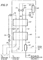
- Figure 3 of the drawings illustrates a further embodiment in which H 2 recovery of a known type is combined with the C 2 hydrocarbon recovery system of the present invention to obtain high H 2 recovery.
- demethanizer column 11 and its auxiliary equipment are omitted from Figure 3 and the uncondensed vapors leaving separator 16 (Figure 1) are introduced via line 18 into phase separator 22.
- the separated vapors flow upwardly via line 24 into dephlegmator 60.
- Uncondensed vapor leaving the top of the dephlegmator 60 via line 61 is subjected to partial condensation in heat exchanger 62 and the resulting H 2 enriched vapor (line 63) and C, enriched liquid (line 64) are separated by means of phase separator 65.
- the liquid in line 64 is reduced in pressure via J-T valve 66, and the vapor in line 63 and the liquid in line 68 are separately warmed in heat exchanger 62 prior to being utilized in dephlegmator 60 to provide the refrigeration necessary for condensation and rectification of the C 2 enriched liquid produced in the dephlegmator (line 25).
- the C, enriched stream is recovered from dephlegmator 60 via line 70 and the H 2 enriched vapor is recovered via line 71.
- additional refrigeration may be provided by means to increase C 2 hydrocarbon recovery, such as J-T expansion by passing a portion of the H 2 enriched vapor in line 63 through J-T valve 73 or work expansion of the H 2 enriched vapor in line 71 through expander 75.
- the H 2 enriched stream is then returned either through heat exchanger 62 via line 76 and dephlegmator 60 via line 78 or only through dephlegmator 60 before the stream is discharged therefrom via line 80.
- a portion of the H 2 enriched stream in line 63 may also be combined with the C, enriched liquid in line 68 via line 82 and valve 83 to enhance refrigeration recovery.
- the mixed vapor-liquid stream charged to the demethanizer column of an ethylene plant is composed of:
- the vapor fraction is cooled in reflux condenser 15 to 174°K and introduced into phase separator 16 from which the condensed liquid fraction is returned to the demethanizer column as a reflux liquid fraction via line 17.
- the overhead vapor fraction from the main reflux condenser is sent to the cryogenic unit 19 via line 18. It is comprised of and 0.2 mol % of ethane, carbon monoxide and propane.
- the stream In passing through the dephlegmator 21, the stream is cooled to 169°K by heat exchange with the returning stream in line 29, effecting condensation and rectification of a portion thereof drained (via line 24) into the phase separator 22.
- the liquid returned as auxiliary reflux to the demethanizer column 11 (via line 25) is composed chiefly of 88.5% methane and 9% ethylene, at an attained temperature of 173°K.
- the refrigeration for the dephlegmator 21 in the illustrated embodiment of Figure 1 is provided by reducing the pressure of the uncondensed vapor in line 26 to 115 psia (8.1 kg/cm 2 ) with consequent reduction in temperature to 144°K.
- the warmed off gas discharged through line 30 at 173°K comprises 72% methane and 27% hydrogen. It contains less than 0.6 mol % of ethylene, which constitutes less than 1% of that initially present in the mixed feed charged to the demethanizer column.
- the liquid product recovered from the demethanizer (line 35) at 502 psia (35.3 kg/cm 2 ) and 288°K comprises:
- the ethylene recovery from the dephlegmator is over 70% of that present in the vapor stream entering the dephlegmator, in addition to which 90% or more of the ethane is recovered.
- the mixed feed to the demethanizer column contains
- the vapor overhead stream from the main reflux condenser is introduced into the dephlegmator 40 ( Figure 2) at a temperature of 174°K and at a pressure of 497 psia (35 kg/cm 2 ).
- the vapor stream is initially cooled in the dephlegmator to 168°K and split into a portion (line 42) going to hydrogen recovery and a high pressure stream (line 43).
- the high pressure stream is flashed via J-T valve 44 to a reduced pressure of 370 psia (26 kg/cm 2 ) with resulting reduction in temperature to 161°K and is passed through the dephlegmator as a refrigerant via line 46.
- the exiting stream in line 48 at 173°K is further reduced in pressure by work expansion in turbine 50 to a pressure of 123 psia (8.65 kg/cm 2 ) with resulting reduction in temperature to 139°K and is returned as refrigerant in the dephlegmator via line 51.
- the several streams recovered from the dephlegmator have the following compositions respectively.
- the off gases discharged from the dephlegmator through lines 45 and 52 contain less than 0.2 mol % ethylene, which constitutes about 0.3% of that initally charged to the demethanizer column.
- the liquid bottoms fraction recovered from the demethanizer column (line 35, Figure 1) at 505 psia (35.5 kg/cm 2 ) and 289°K comprises:
- the ethylene recovery from the dephlegmator constitutes 92+% of that present in the vapor feed charged to the dephlegmator, in addition to which 99% or more of the ethane is recovered.
- Example 1 Figure 1
- Example 2 Figure 2
- H 2 recovery since the stream does not undergo pressure reduction, no refrigeration is obtained from the stream and some C 2 hydrocarbon recovery is therefore lost.
Landscapes
- Engineering & Computer Science (AREA)
- Chemical & Material Sciences (AREA)
- Mechanical Engineering (AREA)
- Thermal Sciences (AREA)
- General Engineering & Computer Science (AREA)
- Physics & Mathematics (AREA)
- Organic Chemistry (AREA)
- Chemical Kinetics & Catalysis (AREA)
- Oil, Petroleum & Natural Gas (AREA)
- Water Supply & Treatment (AREA)
- Analytical Chemistry (AREA)
- Organic Low-Molecular-Weight Compounds And Preparation Thereof (AREA)
- Separation By Low-Temperature Treatments (AREA)
Claims (10)
Applications Claiming Priority (2)
| Application Number | Priority Date | Filing Date | Title |
|---|---|---|---|
| US06/092,894 US4270940A (en) | 1979-11-09 | 1979-11-09 | Recovery of C2 hydrocarbons from demethanizer overhead |
| US92894 | 1979-11-09 |
Publications (2)
| Publication Number | Publication Date |
|---|---|
| EP0029678A1 EP0029678A1 (fr) | 1981-06-03 |
| EP0029678B1 true EP0029678B1 (fr) | 1983-05-11 |
Family
ID=22235675
Family Applications (1)
| Application Number | Title | Priority Date | Filing Date |
|---|---|---|---|
| EP80304004A Expired EP0029678B1 (fr) | 1979-11-09 | 1980-11-10 | Récupération d'hydrocarbures en C2 à partir d'un courant de tête d'un déméthaniseur |
Country Status (6)
| Country | Link |
|---|---|
| US (1) | US4270940A (fr) |
| EP (1) | EP0029678B1 (fr) |
| JP (1) | JPS5829924B2 (fr) |
| CA (1) | CA1129764A (fr) |
| DE (1) | DE3063180D1 (fr) |
| ES (1) | ES496736A0 (fr) |
Cited By (2)
| Publication number | Priority date | Publication date | Assignee | Title |
|---|---|---|---|---|
| US11892447B2 (en) | 2015-12-16 | 2024-02-06 | Laboratoires Expanscience | Method for evaluating the effects of dehydration on children's skin |
| US12061189B2 (en) | 2017-06-22 | 2024-08-13 | Laboratoires Expanscience | Models of reconstructed sensitive skin |
Families Citing this family (29)
| Publication number | Priority date | Publication date | Assignee | Title |
|---|---|---|---|---|
| US4519825A (en) * | 1983-04-25 | 1985-05-28 | Air Products And Chemicals, Inc. | Process for recovering C4 + hydrocarbons using a dephlegmator |
| US4714487A (en) * | 1986-05-23 | 1987-12-22 | Air Products And Chemicals, Inc. | Process for recovery and purification of C3 -C4+ hydrocarbons using segregated phase separation and dephlegmation |
| US4707170A (en) * | 1986-07-23 | 1987-11-17 | Air Products And Chemicals, Inc. | Staged multicomponent refrigerant cycle for a process for recovery of C+ hydrocarbons |
| US4732598A (en) * | 1986-11-10 | 1988-03-22 | Air Products And Chemicals, Inc. | Dephlegmator process for nitrogen rejection from natural gas |
| US4720293A (en) * | 1987-04-28 | 1988-01-19 | Air Products And Chemicals, Inc. | Process for the recovery and purification of ethylene |
| US5186908A (en) * | 1988-10-07 | 1993-02-16 | Mobil Oil Corporation | Increased conversion of C2 -C12 aliphatic hydrocarbons to aromatic hydrocarbons using a highly purified recycle stream |
| US4996381A (en) * | 1988-10-07 | 1991-02-26 | Mobil Oil Corp. | Increased conversion of C2 -C12 aliphatic hydrocarbons to aromatic hydrocarbons using a highly purified recycle stream |
| US4900347A (en) * | 1989-04-05 | 1990-02-13 | Mobil Corporation | Cryogenic separation of gaseous mixtures |
| US5035732A (en) * | 1990-01-04 | 1991-07-30 | Stone & Webster Engineering Corporation | Cryogenic separation of gaseous mixtures |
| US5372009A (en) * | 1993-11-09 | 1994-12-13 | Mobil Oil Corporation | Cryogenic distillation |
| US5502971A (en) * | 1995-01-09 | 1996-04-02 | Abb Lummus Crest Inc. | Low pressure recovery of olefins from refinery offgases |
| US5768913A (en) * | 1997-04-16 | 1998-06-23 | Stone & Webster Engineering Corp. | Process based mixed refrigerants for ethylene plants |
| US5802871A (en) * | 1997-10-16 | 1998-09-08 | Air Products And Chemicals, Inc. | Dephlegmator process for nitrogen removal from natural gas |
| US5983665A (en) * | 1998-03-03 | 1999-11-16 | Air Products And Chemicals, Inc. | Production of refrigerated liquid methane |
| US6343487B1 (en) | 2001-02-22 | 2002-02-05 | Stone & Webster, Inc. | Advanced heat integrated rectifier system |
| RU2217668C2 (ru) * | 2001-12-19 | 2003-11-27 | Общество с ограниченной ответственностью "Оренбурггазпром" | Способ переработки углеводородного сырья |
| CN100551885C (zh) * | 2005-09-29 | 2009-10-21 | 中国石油化工集团公司 | 从制备烯烃的产品气中回收低碳烯烃的方法 |
| US8973398B2 (en) | 2008-02-27 | 2015-03-10 | Kellogg Brown & Root Llc | Apparatus and method for regasification of liquefied natural gas |
| US8309776B2 (en) * | 2009-12-15 | 2012-11-13 | Stone & Webster Process Technology, Inc. | Method for contaminants removal in the olefin production process |
| FR2993282B1 (fr) | 2012-07-13 | 2017-11-10 | Expanscience Lab | Procede d'identification de marqueurs moleculaires de la peau d'enfant |
| FR3011008B1 (fr) | 2013-09-24 | 2017-12-29 | Expanscience Lab | Procedes d'evaluation des effets deleteres des uv sur la peau d'enfant |
| FR3016373B1 (fr) | 2014-01-10 | 2018-01-19 | Laboratoires Expanscience | Modele de peau de mammelon reconstitue |
| FR3019186B1 (fr) | 2014-03-31 | 2019-06-07 | Laboratoires Expanscience | Procedes d'evaluation des effets deleteres de l'urine sur la peau d'enfant |
| WO2016053668A1 (fr) | 2014-09-30 | 2016-04-07 | Dow Global Technologies Llc | Procédé pour augmenter le rendement d'éthylène et de propylène d'une installation de production de propylène |
| EA032725B1 (ru) * | 2015-06-29 | 2019-07-31 | Линде Акциенгезельшафт | Способ и устройство для получения водорода из сырьевой смеси, которая содержит водород и углеводороды |
| US20180298292A1 (en) | 2015-09-29 | 2018-10-18 | Sabic Global Technologies B.V. | Cyrogenic separation of light olefins and methane from syngas |
| FR3053053B1 (fr) | 2016-06-23 | 2018-07-13 | Laboratoires Expanscience | Modeles de la dermatite atopique juvenile |
| FR3133198B1 (fr) | 2022-03-04 | 2025-11-21 | Pierre Fabre Dermo Cosmetique | Modele de peau reconstituee |
| FR3138149A1 (fr) | 2022-07-25 | 2024-01-26 | Pierre Fabre Dermo-Cosmetique | Méthode d’évaluation in vitro de l’activité photoprotectrice d’un actif |
Family Cites Families (13)
| Publication number | Priority date | Publication date | Assignee | Title |
|---|---|---|---|---|
| BE353298A (fr) * | 1927-09-30 | |||
| US2582068A (en) * | 1948-12-30 | 1952-01-08 | Elliott Co | Method and apparatus for separating gases |
| US2775103A (en) * | 1954-12-23 | 1956-12-25 | Phillips Petroleum Co | Hydrocarbon separation |
| US3262278A (en) * | 1963-08-19 | 1966-07-26 | Exxon Research Engineering Co | Increased ethylene recovery by ethane addition |
| US3320754A (en) * | 1964-09-25 | 1967-05-23 | Lummus Co | Demethanization in ethylene recovery with condensed methane used as reflux and heat exchange medium |
| DE1268162B (de) * | 1965-07-28 | 1968-05-16 | Linde Ag | Verfahren zum Zerlegen eines Gasgemisches |
| US3359743A (en) * | 1966-04-29 | 1967-12-26 | Nat Distillers Chem Corp | Low temperature process for the recovery of ethane from a stripped natural gas stream |
| US3360946A (en) * | 1966-04-29 | 1968-01-02 | Nat Distillers Chem Corp | Low temperature process for the recovery of ethane from a stripped natural gas stream |
| US3702541A (en) * | 1968-12-06 | 1972-11-14 | Fish Eng & Construction Inc | Low temperature method for removing condensable components from hydrocarbon gas |
| BE758567A (fr) * | 1969-11-07 | 1971-05-06 | Fluor Corp | Procede de recuperation d'ethylene a basse pression |
| US3902329A (en) * | 1970-10-28 | 1975-09-02 | Univ California | Distillation of methane and hydrogen from ethylene |
| JPS4948287B1 (fr) * | 1970-11-26 | 1974-12-20 | ||
| US4002042A (en) * | 1974-11-27 | 1977-01-11 | Air Products And Chemicals, Inc. | Recovery of C2 + hydrocarbons by plural stage rectification and first stage dephlegmation |
-
1979
- 1979-11-09 US US06/092,894 patent/US4270940A/en not_active Expired - Lifetime
-
1980
- 1980-11-04 CA CA363,949A patent/CA1129764A/fr not_active Expired
- 1980-11-10 ES ES496736A patent/ES496736A0/es active Granted
- 1980-11-10 DE DE8080304004T patent/DE3063180D1/de not_active Expired
- 1980-11-10 JP JP55158078A patent/JPS5829924B2/ja not_active Expired
- 1980-11-10 EP EP80304004A patent/EP0029678B1/fr not_active Expired
Cited By (2)
| Publication number | Priority date | Publication date | Assignee | Title |
|---|---|---|---|---|
| US11892447B2 (en) | 2015-12-16 | 2024-02-06 | Laboratoires Expanscience | Method for evaluating the effects of dehydration on children's skin |
| US12061189B2 (en) | 2017-06-22 | 2024-08-13 | Laboratoires Expanscience | Models of reconstructed sensitive skin |
Also Published As
| Publication number | Publication date |
|---|---|
| US4270940A (en) | 1981-06-02 |
| DE3063180D1 (en) | 1983-06-16 |
| JPS5690019A (en) | 1981-07-21 |
| ES8200855A1 (es) | 1981-11-16 |
| CA1129764A (fr) | 1982-08-17 |
| EP0029678A1 (fr) | 1981-06-03 |
| JPS5829924B2 (ja) | 1983-06-25 |
| ES496736A0 (es) | 1981-11-16 |
Similar Documents
| Publication | Publication Date | Title |
|---|---|---|
| US4270940A (en) | Recovery of C2 hydrocarbons from demethanizer overhead | |
| US6308532B1 (en) | System and process for the recovery of propylene and ethylene from refinery offgases | |
| EP0377949B1 (fr) | Procédé et dispositif de récupération des composants C2 | |
| US3983711A (en) | Plural stage distillation of a natural gas stream | |
| US4720293A (en) | Process for the recovery and purification of ethylene | |
| US4705549A (en) | Separation of C3+ hydrocarbons by absorption and rectification | |
| US4512782A (en) | Multistage rectification of gaseous hydrocarbons containing sour gases | |
| US4881960A (en) | Fractionation of a hydrocarbon mixture | |
| US4525187A (en) | Dual dephlegmator process to separate and purify syngas mixtures | |
| AU1615799A (en) | Enhanced ngl recovery processes | |
| US5026952A (en) | Process for separating C2 + or C3 + or C4 hydrocarbons from a gaseous mixture | |
| US4732598A (en) | Dephlegmator process for nitrogen rejection from natural gas | |
| EP0669389B1 (fr) | Procédé pour la récuperation d'éthylène comprenant une étape de préfroidissement | |
| EP0023838B1 (fr) | Séparation de mélanges de gaz | |
| EP0230754B1 (fr) | Séparation de mélanges gazeux | |
| US4444577A (en) | Cryogenic gas processing | |
| US4272269A (en) | Cryogenic expander recovery process | |
| US3675434A (en) | Separation of low-boiling gas mixtures | |
| CA2082291C (fr) | Integration de la chaleur dans une installation de distillation a colonnes multiples | |
| EP0134243B1 (fr) | Dispositif et procede d'extraction d'hydrocarbures legers a partir de gaz contenant de l'hydrogene | |
| US3355902A (en) | Helium recovery process | |
| US4885063A (en) | Method and apparatus for olefin recovery | |
| US4664687A (en) | Process for the separation of C2+, C3+ or C4+ hydrocarbons | |
| EP0283213A2 (fr) | Procédé de récupération de l'argon | |
| US3915680A (en) | Separation of low-boiling gas mixtures |
Legal Events
| Date | Code | Title | Description |
|---|---|---|---|
| PUAI | Public reference made under article 153(3) epc to a published international application that has entered the european phase |
Free format text: ORIGINAL CODE: 0009012 |
|
| AK | Designated contracting states |
Designated state(s): BE DE FR GB IT NL |
|
| 17P | Request for examination filed |
Effective date: 19810421 |
|
| ITF | It: translation for a ep patent filed | ||
| GRAA | (expected) grant |
Free format text: ORIGINAL CODE: 0009210 |
|
| AK | Designated contracting states |
Designated state(s): BE DE FR GB IT NL |
|
| REF | Corresponds to: |
Ref document number: 3063180 Country of ref document: DE Date of ref document: 19830616 |
|
| ET | Fr: translation filed | ||
| PLBI | Opposition filed |
Free format text: ORIGINAL CODE: 0009260 |
|
| 26 | Opposition filed |
Opponent name: LINDE AKTIENGESELLSCHAFT, WIESBADEN Effective date: 19831213 |
|
| PGFP | Annual fee paid to national office [announced via postgrant information from national office to epo] |
Ref country code: FR Payment date: 19841011 Year of fee payment: 5 |
|
| PGFP | Annual fee paid to national office [announced via postgrant information from national office to epo] |
Ref country code: DE Payment date: 19841031 Year of fee payment: 5 |
|
| PGFP | Annual fee paid to national office [announced via postgrant information from national office to epo] |
Ref country code: BE Payment date: 19841231 Year of fee payment: 5 |
|
| PGFP | Annual fee paid to national office [announced via postgrant information from national office to epo] |
Ref country code: NL Payment date: 19851130 Year of fee payment: 6 |
|
| RDAG | Patent revoked |
Free format text: ORIGINAL CODE: 0009271 |
|
| STAA | Information on the status of an ep patent application or granted ep patent |
Free format text: STATUS: PATENT REVOKED |
|
| 27W | Patent revoked |
Effective date: 19860621 |
|
| NLR2 | Nl: decision of opposition | ||
| BERE | Be: lapsed |
Owner name: AIR PRODUCTS AND CHEMICALS INC. Effective date: 19861130 |
|
| GBPC | Gb: european patent ceased through non-payment of renewal fee | ||
| REG | Reference to a national code |
Ref country code: FR Ref legal event code: ST |