EP0029879A2 - Procédé et dispositif pour l'obtention par voie thermique de carbures métalliques ou de métaux - Google Patents
Procédé et dispositif pour l'obtention par voie thermique de carbures métalliques ou de métaux Download PDFInfo
- Publication number
- EP0029879A2 EP0029879A2 EP80104908A EP80104908A EP0029879A2 EP 0029879 A2 EP0029879 A2 EP 0029879A2 EP 80104908 A EP80104908 A EP 80104908A EP 80104908 A EP80104908 A EP 80104908A EP 0029879 A2 EP0029879 A2 EP 0029879A2
- Authority
- EP
- European Patent Office
- Prior art keywords
- metal
- aluminum
- carbon
- extraction
- carbide
- Prior art date
- Legal status (The legal status is an assumption and is not a legal conclusion. Google has not performed a legal analysis and makes no representation as to the accuracy of the status listed.)
- Granted
Links
Images



Classifications
-
- C—CHEMISTRY; METALLURGY
- C22—METALLURGY; FERROUS OR NON-FERROUS ALLOYS; TREATMENT OF ALLOYS OR NON-FERROUS METALS
- C22B—PRODUCTION AND REFINING OF METALS; PRETREATMENT OF RAW MATERIALS
- C22B5/00—General methods of reducing to metals
- C22B5/02—Dry methods smelting of sulfides or formation of mattes
- C22B5/10—Dry methods smelting of sulfides or formation of mattes by solid carbonaceous reducing agents
-
- C—CHEMISTRY; METALLURGY
- C01—INORGANIC CHEMISTRY
- C01B—NON-METALLIC ELEMENTS; COMPOUNDS THEREOF; METALLOIDS OR COMPOUNDS THEREOF NOT COVERED BY SUBCLASS C01C
- C01B21/00—Nitrogen; Compounds thereof
- C01B21/082—Compounds containing nitrogen and non-metals and optionally metals
- C01B21/0828—Carbonitrides or oxycarbonitrides of metals, boron or silicon
-
- C—CHEMISTRY; METALLURGY
- C01—INORGANIC CHEMISTRY
- C01B—NON-METALLIC ELEMENTS; COMPOUNDS THEREOF; METALLOIDS OR COMPOUNDS THEREOF NOT COVERED BY SUBCLASS C01C
- C01B32/00—Carbon; Compounds thereof
- C01B32/90—Carbides
-
- C—CHEMISTRY; METALLURGY
- C01—INORGANIC CHEMISTRY
- C01B—NON-METALLIC ELEMENTS; COMPOUNDS THEREOF; METALLOIDS OR COMPOUNDS THEREOF NOT COVERED BY SUBCLASS C01C
- C01B32/00—Carbon; Compounds thereof
- C01B32/90—Carbides
- C01B32/914—Carbides of single elements
-
- C—CHEMISTRY; METALLURGY
- C01—INORGANIC CHEMISTRY
- C01B—NON-METALLIC ELEMENTS; COMPOUNDS THEREOF; METALLOIDS OR COMPOUNDS THEREOF NOT COVERED BY SUBCLASS C01C
- C01B32/00—Carbon; Compounds thereof
- C01B32/90—Carbides
- C01B32/914—Carbides of single elements
- C01B32/921—Titanium carbide
-
- C—CHEMISTRY; METALLURGY
- C01—INORGANIC CHEMISTRY
- C01B—NON-METALLIC ELEMENTS; COMPOUNDS THEREOF; METALLOIDS OR COMPOUNDS THEREOF NOT COVERED BY SUBCLASS C01C
- C01B33/00—Silicon; Compounds thereof
- C01B33/02—Silicon
-
- C—CHEMISTRY; METALLURGY
- C01—INORGANIC CHEMISTRY
- C01B—NON-METALLIC ELEMENTS; COMPOUNDS THEREOF; METALLOIDS OR COMPOUNDS THEREOF NOT COVERED BY SUBCLASS C01C
- C01B35/00—Boron; Compounds thereof
- C01B35/02—Boron; Borides
- C01B35/023—Boron
-
- C—CHEMISTRY; METALLURGY
- C01—INORGANIC CHEMISTRY
- C01B—NON-METALLIC ELEMENTS; COMPOUNDS THEREOF; METALLOIDS OR COMPOUNDS THEREOF NOT COVERED BY SUBCLASS C01C
- C01B35/00—Boron; Compounds thereof
- C01B35/02—Boron; Borides
- C01B35/04—Metal borides
-
- C—CHEMISTRY; METALLURGY
- C22—METALLURGY; FERROUS OR NON-FERROUS ALLOYS; TREATMENT OF ALLOYS OR NON-FERROUS METALS
- C22B—PRODUCTION AND REFINING OF METALS; PRETREATMENT OF RAW MATERIALS
- C22B1/00—Preliminary treatment of ores or scrap
- C22B1/14—Agglomerating; Briquetting; Binding; Granulating
- C22B1/24—Binding; Briquetting ; Granulating
- C22B1/242—Binding; Briquetting ; Granulating with binders
- C22B1/244—Binding; Briquetting ; Granulating with binders organic
- C22B1/245—Binding; Briquetting ; Granulating with binders organic with carbonaceous material for the production of coked agglomerates
-
- C—CHEMISTRY; METALLURGY
- C22—METALLURGY; FERROUS OR NON-FERROUS ALLOYS; TREATMENT OF ALLOYS OR NON-FERROUS METALS
- C22B—PRODUCTION AND REFINING OF METALS; PRETREATMENT OF RAW MATERIALS
- C22B21/00—Obtaining aluminium
- C22B21/0038—Obtaining aluminium by other processes
- C22B21/0053—Obtaining aluminium by other processes from other aluminium compounds
-
- H—ELECTRICITY
- H05—ELECTRIC TECHNIQUES NOT OTHERWISE PROVIDED FOR
- H05B—ELECTRIC HEATING; ELECTRIC LIGHT SOURCES NOT OTHERWISE PROVIDED FOR; CIRCUIT ARRANGEMENTS FOR ELECTRIC LIGHT SOURCES, IN GENERAL
- H05B3/00—Ohmic-resistance heating
- H05B3/60—Heating arrangements wherein the heating current flows through granular powdered or fluid material, e.g. for salt-bath furnace, electrolytic heating
-
- C—CHEMISTRY; METALLURGY
- C01—INORGANIC CHEMISTRY
- C01P—INDEXING SCHEME RELATING TO STRUCTURAL AND PHYSICAL ASPECTS OF SOLID INORGANIC COMPOUNDS
- C01P2004/00—Particle morphology
- C01P2004/50—Agglomerated particles
Definitions
- the invention relates to a method and a device for the thermal extraction of a group of metal carbides or metals, wherein a mixture of metal oxide and carbon is reduced to metal carbide and the metal is optionally extracted from the metal carbide.
- This group comprises the carbide-forming metallic elements, aluminum, boron, silicon, titanium, zirconium, tantalum, niobium, molybdenum, tungsten and uranium, which are difficult to reduce their oxides.
- the thermal extraction processes of the metal carbides or metals mentioned are generally quite different and tailored to the respective metal.
- the process according to the invention allows these metal carbides and, in some cases, the metals to be extracted therefrom to be produced according to a common principle.
- aluminum as an example, the fundamental problems of carbothermal reduction of oxides which are difficult to reduce and, on the other hand, details of the process according to the invention are to be described in more detail.
- the chemical difficulties are primarily due to the fact that, in accordance with the thermodynamics in the reduction of aluminum oxide with carbon, aluminum carbide, A1 4 C 3 , is initially formed via the intermediate stage of the oxicarbide.
- Aluminum carbide formation is fundamentally favored over aluminum formation.
- a reduced carbon supply during the reduction process can suppress the formation of aluminum carbide and increase the aluminum content.
- the competitive reaction leading to the formation of volatile aluminum suboxide, A1 2 0 is increasingly supported. Therefore, an increased volatilization of the aluminum oxide used is to be expected if one wants to increase the aluminum formation in the known processes.
- the aluminum carbide which is preferably formed dissolves both in the aluminum oxide and in the aluminum.
- the dissolved aluminum carbide can be converted further to aluminum with aluminum oxide, but under practical conditions this reaction does not proceed exclusively towards aluminum.
- Another aggravating circumstance is the relatively narrow temperature range of 2050 to 2150 ° C, which must be observed for the aluminum oxide reaction in order to achieve a favorable yield of aluminum.
- An undesirable evaporation of the aluminum is noticeable from 2000 ° C.
- the preferred reduction temperatures are 1950 to 2050 ° C. according to the invention aimed for aluminum carbide formation. At these temperatures and with a sufficient supply of carbon, the evaporation losses due to the aluminum suboxide and aluminum can be kept quite low.
- the necessary narrowly limited temperature control around 2000 ° C is a major technical problem for the reduction process for the production of aluminum carbide.
- the physical difficulties of carbothermal aluminum production are, on the one hand, that the molten aluminum oxide (melting point around 2050 ° C) is specifically heavier than the liquid aluminum.
- a molten mixture of aluminum oxide, aluminum carbide and carbon accumulates on the bottom of the reduction furnace rather than cut-off aluminum.
- Graphitized carbon which can form during the reduction process, also has approximately the same density as the liquid aluminum.
- An enrichment of aluminum carbide leads to difficult-to-melt approaches, since aluminum carbide is a solid phase and increases the melting points of the binary mixtures at higher concentrations in aluminum oxide or aluminum.
- a three-stage process for the thermal extraction of aluminum has also become known, in which aluminum carbide is produced as an intermediate. With a limited amount of carbon, the aluminum oxide is reduced to a gaseous mixture of A1 2 0, Al steam and CO. The mixture of A1 2 0 and Al steam distilled off from the reduction furnace is then reacted with an excess of carbon to form aluminum carbide. In a third stage, the aluminum carbide is decomposed into aluminum and carbon at temperatures of 2000 ° C and under a pressure of 20 to 50 torr. The aluminum is condensed liquid or solid.
- the shortcomings of this three-stage process are that, on the one hand, the thermal decomposition of the aluminum carbide under vacuum is extremely difficult to accomplish. The complete conversion of A1 2 0 with the carbon to A1 4 C 3 and the back reaction of Al steam with CO present further difficulties.
- the object of the present invention is to avoid the disadvantages of the known methods and to enable a continuous extraction of aluminum carbide and metallic aluminum. According to the invention this is achieved in that the mixture of aluminum oxide and carbon is agglomerated, each piece of agglomerate is coated with carbon and / or graphite, the bodies thus produced are coked and reduced in a tightly packed bed and the aluminum is obtained from the aluminum carbide obtained in this way is extracted with aluminum fluoride.
- the first essential step of the method according to the invention consists in the selection of the suitable feed material and its preparation.
- the finely divided aluminum oxide is mixed with a bindable carbon carrier.
- carbon binders such as tars, pitches, resins or, in particular, so-called extract substances from the solvent and pressure extraction of hard coal can be used.
- the green mixture of aluminum oxide and carbon binder is agglomerated into small moldings. Agglomeration is understood to mean processes for the fragmentation of finely divided materials, as described in the journal Chemie-Ingenieur-Technik 51 (1979) No. 4, pp. 266-288.
- Preferred moldings are, for example, isometric cylinders, spheres or pillow-shaped briquettes, which can be formed in large numbers on ring rollers or table presses.
- the compressed and molded mixture of aluminum oxide and carbon binder is then surrounded by a shell made of only carbon.
- a shell which is also plastically deformable and which is prepared, for example, from petroleum coke powder and pitch, is used to form the shell.
- the shape of the feed material is comparable to the structure of a hazelnut, the core being the mixture of aluminum oxide and carbon binder and the shell of low-ash coke powder and pitch.
- the carbon shell can be applied by pressing or by rolling up as in pelleting.
- the green moldings are then subjected to a coking process.
- the pitch in the shell and the carbon binder in the core are converted into solid carbon or coke.
- the coked pitch in the shell has the task of a good binding coke, because the carbon shell has to meet high strength requirements.
- the carbon shell is intended to withstand certain pressure, impact and abrasion stresses in the subsequent process stages. Their wall thickness is measured so that the coating of the core mixture meets the mechanical stresses to which the molded body is exposed.
- the coked carbon shell also has the task of conducting the electrical current. It is namely intended to heat the moldings by means of an electrical resistance heater. In a bed or package of the molded articles according to the invention, the current flows mainly from molded article to molded article via the carbon shell.
- the carbon shell When the aluminum oxide is reduced with carbon to aluminum carbide, the carbon shell remains as a stable housing.
- the carbon shell of the moldings ensures that the electrical resistance conditions and the heat input remain largely unaffected by the changes in the core during the reduction.
- the reducing gas leaves the core via the pore channels that are naturally present in the carbon shell.
- the carbon shell also serves as a small transport vessel for the aluminum carbide reaction product.
- the strength of the core mixture of oxide and coke is of minor importance.
- the coking residue of the carbon binder in the core mixture should serve as a reduction carbon for the aluminum oxide and be sufficient for the reduction to the aluminum carbide.
- the coke content or the reduction carbon should be approx. 30-35%.
- Figure 1 the section through a spherical shaped body of the feed material is shown.
- a denotes the carbon shell and b the core mixture of aluminum oxide and carbon.
- the green moldings must be coked or fired before they can be used in the electric reduction furnaces. Firing takes place either separately from the reduction furnace in shaft, tunnel or rotary tube furnaces up to temperatures of around 800 - 1000 ° C.
- the shaped bodies can also be fired directly in a preliminary stage of the reduction furnace. Since the moldings have to be heated to the reduction temperature anyway, energy is saved by a combined furnace unit for burning and reducing.
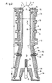
- the combined combustion and reduction furnace is shown in FIG.
- the indirectly heated shaft part I of the furnace the moldings are heated and fired in the process.
- furnace part II the aluminum oxide is reduced by direct electrical resistance heating.
- the reduced goods are discharged in furnace part III.
- the feed material from the shaped bodies is charged into the vertical muffle chamber 3 via the funnel 1 and the diving bell 2.
- the volatile constituents are released from the pitch in the shells and the binder of the core mixture in the case of moldings which are given in green.
- the reducing gas from furnace part II which mainly consists of carbon monoxide
- the volatile constituents leave the muffle room 3 through the slanted windows 11.
- a part of the gas mixture of volatile constituents and reducing gas is passed into the heating trains 8 and with preheated air, which flows through the channels 13 is fed, burned.
- the hot exhaust gases leave shaft part I via duct 12. From there they are passed on to a heat exchanger (recuperator) for air preheating.
- the other part of the gas mixture is drawn off via line 14 and otherwise burned, for example in a boiler system.
- the distribution of the gas streams in the heating cables 8 and in the line 14 is by Valves 15 regulated.
- the heat of combustion of the gas mixture of reducing gas and volatile components of the feed is considerably greater than is required for the external heating of the muffle.
- the moldings reach a temperature of approximately 1300 ° C.
- the pre-fired, solid molded articles of the charge enter the reduction chamber 16 of the furnace part II.
- the electric current for heating the charge is supplied through the side electrodes 20/21 and the central electrode 23/24.
- the electrodes 20 and 23 are made of electrographite and are screwed onto the water-cooled shafts 21 and 24, respectively.
- the current be it alternating or direct current, flows out of the shaped bodies via the bed.
- the current is controlled in such a way that temperatures of 1950 to 2050 ° C. are reached and the core mixture of the shaped bodies is converted into aluminum carbide.
- the furnace part II is lined with carbon stones 17 on the inside.
- the heat-insulating layer 18 made of ceramic refractory material is located between the carbon masonry 17 and the water-cooled outer jacket 19.
- the moldings which are reduced in their core and contain aluminum carbide, are discharged in the hot state via the fireproof-lined channels 25 and then via the vibrating channels 27.
- the discharge temperature is around 1500 - 1600 ° C.
- turntables or screw conveyors can also be used.
- the outfeed and transfer of the reduced feed material into the transport container or directly into the downstream extraction reactor takes place with the exclusion of air.
- the carbide extraction process according to the invention described above for aluminum can also be applied analogously to other carbide-forming, difficult-to-reduce metals such as For example, use boron, silicon, titanium, zirconium, tantalum, niobium, molybdenum, tungsten or uranium, the reduction of which in arc furnaces is similar to that of the electrothermal A1 2 0 3 reduction.
- the advantage of the process according to the invention is above all that the carbides of the metals mentioned above can be obtained continuously.
- the manufacturing processes that have become known for these metal carbides operate discontinuously. It is also possible to obtain high-melting borides, for example titanium boride or zirconium boride, directly from the oxides in question in a continuous process.
- the aluminum carbide obtained from the carbothermal alumina reduction in carbon capsules is an intermediate product from which the aluminum has to be extracted.
- the aluminum is extracted with gaseous aluminum fluoride, A1F 3 , at temperatures above 1100 ° C. (AlF 3 sublimes at about 1100 ° C). It is known that aluminum fluoride reacts with aluminum at high temperatures and forms gaseous aluminum subfluoride, A1F, which disproportionates again in aluminum and aluminum fluoride when the temperature drops.
- the transport reaction over the aluminum subfluoride can be used for the extraction of the aluminum from its carbide. Temperatures of 1500 to 1600 ° C are necessary for the conversion of aluminum carbide with aluminum fluoride to aluminum subfluoride.
- the process according to the invention now provides for a temperature difference to be maintained in a closed reactor space between the reaction sites for the formation and disproportionation of the aluminum subfluoride, which permits an automatic cycle of aluminum extraction.
- the extraction reactor consists of the central, cylindrical reaction space 30 and the annular space 31.
- the central reaction space 30 is formed by a thick-walled graphite tube 32 with inclined windows 33. Because of its large dimensions, the graphite tube 32 is constructed from individual rings placed one inside the other. Above and below, the graphite tube 32 ends in connection rings 34 made of graphite, into which power supply bolts 35 are screwed. The contact pressure between the graphite tube 32 and the connecting rings 34 is ensured by the compression springs 36.
- the graphite tube 32 is heated with electricity using the resistance method.
- the reactor On its outer circumference, the reactor is lined with stones 37 containing high A1 2 0 3 content.
- the material containing aluminum carbide is introduced into the central reaction space 30 via the lockable antechamber 38 with an inlet temperature of over 1100 ° C.
- the carbon material remaining after the aluminum extraction is discharged through the cooling space 44 and then via the discharge plate 39 with a scraper 40.
- the central reaction space 30 is charged with aluminum fluoride in addition to the material containing aluminum carbide.
- the temperatures in the reaction chamber 30 of approx. 1500 - 1600 ° C allow the aluminum fluoride to evaporate. It condenses in a layer 41 on the reactor wall 37.
- the aluminum fluoride layer 41 provides additional thermal insulation, and its thickness increases with sufficient A1F 3 supply until the temperature on the inner surface of layer 41 'rises to over 1100 ° C.
- A1F 3 reacts at temperatures between 1500 and 1600 ° C. with the aluminum carbide to form A1F, which then diffuses to the cooler reactor wall 37 or to the condensed A1F 3 layer 41, where it is in aluminum and again gaseous A1F 3 disproportionate.
- aluminum is constantly from the interior of the graphite tube through the Window 33 and the annular space 31 transported to the surrounding wall 41/37.
- the temperature of the feed material to be extracted must be higher in the transition area from the antechamber 18 to the central reaction space 30 than the condensation temperature on the surface of the layer 41, so that no aluminum is deposited on the feed.
- the feed material is introduced into the extraction reactor through the charging opening 46 and the fireproof slide closure 45 which is opened when filling.
- This charging device can also be designed differently, e.g. through a structure with bell or flap lock.
- the requirement for the discharge temperature of the carbon material remaining after the extraction also applies that it is above the surface temperature of the layer 41. In the upper section of the cooling space 44, the carbon residues themselves provide effective downward thermal insulation and thus prevent the A1F from being disproportionated there.
- the extraction reactor can have a circular or rectangular cross section. Several extraction units can also be assembled to form a battery.
- the aluminum oxide-carbon mixture is coated with a stable carbon shell and the A1 2 0 3 -C core is reduced to aluminum carbide in the reduction furnace (FIG. 2).
- the carbon shell is expediently broken or blasted before entering the extraction reactor in order to allow the A1F 3 easier access to the aluminum carbide. Basically, this is the extract discharged carbon material returned to the process cycle, ie reused for the preparation of the Al 2 O 3 -carbon mixture or for the carbon coating.
- prefabricated carbon or graphite vessels for holding the aluminum oxide-carbon binder mixture. It is not necessary that the carbon containers surround the A1 2 0 3 -C mixture on all sides.
- Preferred one- or two-sided open vessel shapes are cylindrical crucibles or sleeves. Prefabricated carbon and graphite vessels are expediently used several times in the cycle until they have to be replaced due to wear or breakage.
- Tubes are pressed from a suitable carbon mass on an extrusion press and are burned in a ring kiln.
- the carbon tubes are divided into sections of equal size, ie into sleeves or rings.
- the prefabricated carbon sleeves are pressed in with the plastic mixture of aluminum oxide, petroleum coke powder and a binder based on tar.
- the sleeves can have inwardly directed teeth which are molded during extrusion.
- the filled sleeves serve as feed material both for the reduction furnace according to FIG. 2 and for the extraction reactor according to FIG. 3.
- the A1 2 0 3 -C binder mass is coked in shaft part I of the reduction furnace and reduced to aluminum carbide in reduction part II.
- the carbon sleeve is the supporting housing and the resistance heating element for the Al 2 O 3 -C mass contained therein.
- the A1203-C bandage loses in the manhole section medium mass, for example, 5-20% of its weight and shrinks.
- the coked A1 2 0 3 -C mass suffers a further weight loss of about 55% when reduced to aluminum carbide. Slight shrinkage also occurs here.
- the brown to brown-black aluminum carbide forms a porous, spongy, crushable structure.
- the cavities between the carbon support sleeves allow good diffusion exchange, ie the transport of gaseous A1F 3 to the aluminum carbide and the transport of gaseous A1F.
- FIG. 4 again provides an overview of the individual process steps of the process according to the invention.
- the already mentioned metal carbides of boron, silicon, titanium, zirconium, tantalum, niobium, molybdenum, tungsten or uranium are hard materials used in industry.
- the carbides of titanium, tantalum and tungsten are used in particular for the production of hard metals.
- Titanium carbide, TiC is produced, for example, by the process according to the invention in such a way that a mixture of titanium dioxide, carbon black and pitch is prepared, so that in the coked state, 1 to 3 moles of carbon are used for 1 mole of TiO 2 .
- the mass of titanium dioxide, carbon black and pitch is pressed in graphite sleeves, and the moldings thus obtained are charged in the kiln and reduction furnace according to the invention.
- the reduction to titanium carbide takes place at temperatures of approx. 2000 to 2500 ° C.
- the adherence to narrowly limited temperature ranges is not as important as in the representation of aluminum carbide.
- the reduction Titanium dioxide for example, can be coupled with that of tungsten trioxide in order to directly produce mixed carbides from TiC 'and WC, as are required for the production of hard metals.
Landscapes
- Chemical & Material Sciences (AREA)
- Organic Chemistry (AREA)
- Inorganic Chemistry (AREA)
- Engineering & Computer Science (AREA)
- Manufacturing & Machinery (AREA)
- Materials Engineering (AREA)
- Mechanical Engineering (AREA)
- Metallurgy (AREA)
- Life Sciences & Earth Sciences (AREA)
- Environmental & Geological Engineering (AREA)
- General Life Sciences & Earth Sciences (AREA)
- Geochemistry & Mineralogy (AREA)
- Geology (AREA)
- Manufacture And Refinement Of Metals (AREA)
- Carbon And Carbon Compounds (AREA)
- Chemical Vapour Deposition (AREA)
- Ceramic Products (AREA)
Priority Applications (1)
| Application Number | Priority Date | Filing Date | Title |
|---|---|---|---|
| AT80104908T ATE7516T1 (de) | 1979-12-04 | 1980-08-18 | Verfahren und vorrichtung zur thermischen gewinnung von metallcarbiden bzw. metallen. |
Applications Claiming Priority (2)
| Application Number | Priority Date | Filing Date | Title |
|---|---|---|---|
| DE2948640 | 1979-12-04 | ||
| DE2948640A DE2948640C2 (de) | 1979-12-04 | 1979-12-04 | Verfahren und Vorrichtung zur thermischen Gewinnung von Aluminium |
Publications (3)
| Publication Number | Publication Date |
|---|---|
| EP0029879A2 true EP0029879A2 (fr) | 1981-06-10 |
| EP0029879A3 EP0029879A3 (en) | 1981-08-19 |
| EP0029879B1 EP0029879B1 (fr) | 1984-05-16 |
Family
ID=6087512
Family Applications (1)
| Application Number | Title | Priority Date | Filing Date |
|---|---|---|---|
| EP80104908A Expired EP0029879B1 (fr) | 1979-12-04 | 1980-08-18 | Procédé et dispositif pour l'obtention par voie thermique de carbures métalliques ou de métaux |
Country Status (10)
| Country | Link |
|---|---|
| US (1) | US4441920A (fr) |
| EP (1) | EP0029879B1 (fr) |
| JP (1) | JPS5693833A (fr) |
| AT (1) | ATE7516T1 (fr) |
| AU (1) | AU549848B2 (fr) |
| BR (1) | BR8006937A (fr) |
| CA (1) | CA1175238A (fr) |
| DE (1) | DE2948640C2 (fr) |
| NO (1) | NO154728C (fr) |
| SU (2) | SU1048981A3 (fr) |
Cited By (1)
| Publication number | Priority date | Publication date | Assignee | Title |
|---|---|---|---|---|
| US6165993A (en) * | 1992-03-23 | 2000-12-26 | University Of Massachusetts Medical Center | DNA vaccines against rotavirus infections |
Families Citing this family (18)
| Publication number | Priority date | Publication date | Assignee | Title |
|---|---|---|---|---|
| JPS6033888B2 (ja) * | 1982-08-24 | 1985-08-06 | 工業技術院長 | 熔鉱炉法アルミニウム製錬用アルミナ質含有原料成形体 |
| US4519048A (en) * | 1982-12-08 | 1985-05-21 | Pitney Bowes Inc. | Postage meter system for communicating platen movement to a microprocessor to signal completion of printing |
| DE3644057A1 (de) * | 1986-12-22 | 1988-06-30 | Vaw Ver Aluminium Werke Ag | Verfahren und vorrichtung zur thermischen und/oder reduzierenden behandlung von festen, koernigen und/oder agglomerierten einsatzmaterialien |
| JPS63199833A (ja) * | 1987-02-13 | 1988-08-18 | Tosoh Corp | 高純度金属クロムの製造方法 |
| RU2157856C2 (ru) * | 1996-04-30 | 2000-10-20 | Лицей N 142 г.Красноярска | Безанодный способ получения алюминия |
| NO306998B1 (no) * | 1998-02-26 | 2000-01-24 | Norsk Hydro As | Fremgangsmåte for fremstilling av aluminium |
| RU2170278C2 (ru) * | 1999-02-16 | 2001-07-10 | Общеобразовательный лицей № 1 | Способ получения первичного алюминия и устройство для его осуществления |
| US20050254543A1 (en) * | 2004-05-13 | 2005-11-17 | Sgl Carbon Ag | Lining for carbothermic reduction furnace |
| US20060042413A1 (en) * | 2004-09-01 | 2006-03-02 | Fruehan Richard J | Method using single furnace carbothermic reduction with temperature control within the furnace |
| RU2280703C2 (ru) * | 2004-11-15 | 2006-07-27 | Закрытое акционерное общество "Траст-Риэлт" | Способ получения алюминия |
| US7753988B2 (en) * | 2007-07-09 | 2010-07-13 | Alcoa Inc. | Use of alumina-carbon agglomerates in the carbothermic production of aluminum |
| CA2692541A1 (fr) * | 2007-08-07 | 2009-02-12 | Dow Corning Corporation | Procede de production de metaux et alliages par reduction carbothermique d'oxydes de metaux |
| US7704443B2 (en) * | 2007-12-04 | 2010-04-27 | Alcoa, Inc. | Carbothermic aluminum production apparatus, systems and methods |
| US20090181313A1 (en) * | 2008-01-14 | 2009-07-16 | Tesa Ag | Pigment layer and method especially for a durable inscription of glass using a high energy radiation |
| JP5387486B2 (ja) * | 2009-10-08 | 2014-01-15 | 新日鐵住金株式会社 | カーボン被覆炭化アルミニウム及びその製造方法 |
| EP2572010A2 (fr) | 2010-05-20 | 2013-03-27 | Dow Corning Corporation | Procédé et système d'obtention d'alliage d'aluminium-silicium |
| RU2524408C1 (ru) * | 2012-11-26 | 2014-07-27 | Александр Сергеевич Буйновский | Способ футерования реторт для получения металлов и сплавов металлотермической восстановительной плавкой |
| US12534777B2 (en) | 2021-11-18 | 2026-01-27 | Martin Samuel Sulsky | Carboaluminothermic reduction apparatus and methods of using |
Family Cites Families (17)
| Publication number | Priority date | Publication date | Assignee | Title |
|---|---|---|---|---|
| CH226053A (de) * | 1940-10-19 | 1943-03-15 | Ig Farbenindustrie Ag | Verfahren zur Sinterung von feinkörnigen Ausgangsstoffen. |
| CH261162A (de) * | 1947-10-25 | 1949-04-30 | Aluminium Ind Ag | Verfahren zur Herstellung von Aluminium. |
| NL174714B (nl) * | 1951-12-19 | Gen Electric | Werkwijze voor het omzetten van hexagonaal boornitride in kubisch boornitride en het toepassen hiervan in snijgereedschap. | |
| US2867525A (en) * | 1955-08-01 | 1959-01-06 | Harvey Machine Co Inc | Agglomerating finely divided aluminum smelting mixtures |
| US2975049A (en) * | 1956-01-05 | 1961-03-14 | Phoenix Steel Corp | Method for producing titanium |
| US3135696A (en) * | 1959-09-03 | 1964-06-02 | Pechiney Prod Chimiques Sa | Process for the preparation of aluminum oxide and carbon based briquettes |
| DE1143029B (de) * | 1960-05-06 | 1963-01-31 | Union Carbide Corp | Pellets fuer metallurgische Reduktionsverfahren und Verfahren zu ihrer Herstellung |
| DE1173665B (de) * | 1961-09-09 | 1964-07-09 | Vaw Ver Aluminium Werke Ag | Verfahren zur Gewinnung von Aluminium |
| DE1182836B (de) * | 1962-01-02 | 1964-12-03 | Aluminium Lab Ltd | Verfahren und Schachtofen zur Gewinnung von Aluminium aus einem aluminiumhaltigen Material durch Subhalogeniddestillation |
| DE1926364C3 (de) * | 1968-06-26 | 1980-10-09 | Union Carbide Corp., New York, N.Y. (V.St.A.) | Verfahren zur Herstellung von Agglomeraten aus Carbiden des Vanadiums, Niobs, Tantals oder Titans |
| US4072512A (en) * | 1970-11-11 | 1978-02-07 | Brusako Jury Ivanovich | Charge for manufacturing aluminium-silicon alloys |
| JPS4936848B1 (fr) * | 1970-12-30 | 1974-10-03 | ||
| US3929456A (en) * | 1972-05-05 | 1975-12-30 | Reynolds Metals Co | Carbothermic production of aluminum |
| NL7315931A (fr) * | 1972-12-04 | 1974-06-06 | ||
| JPS5152917A (fr) * | 1974-11-05 | 1976-05-11 | Japan Metals & Chem Co Ltd | |
| US4080508A (en) * | 1976-03-17 | 1978-03-21 | Greenewald Jr Herbert | Manufacture of carbides and the like |
| US4216010A (en) * | 1979-01-31 | 1980-08-05 | Reynolds Metals Company | Aluminum purification system |
-
1979
- 1979-12-04 DE DE2948640A patent/DE2948640C2/de not_active Expired
-
1980
- 1980-08-18 AT AT80104908T patent/ATE7516T1/de not_active IP Right Cessation
- 1980-08-18 NO NO802455A patent/NO154728C/no unknown
- 1980-08-18 EP EP80104908A patent/EP0029879B1/fr not_active Expired
- 1980-08-28 SU SU802979299A patent/SU1048981A3/ru active
- 1980-10-07 AU AU63018/80A patent/AU549848B2/en not_active Ceased
- 1980-10-29 BR BR8006937A patent/BR8006937A/pt unknown
- 1980-11-28 US US06/211,054 patent/US4441920A/en not_active Expired - Lifetime
- 1980-12-03 CA CA000366101A patent/CA1175238A/fr not_active Expired
- 1980-12-03 JP JP16972080A patent/JPS5693833A/ja active Pending
-
1982
- 1982-11-24 SU SU3513564A patent/SU1253433A3/ru active
Cited By (1)
| Publication number | Priority date | Publication date | Assignee | Title |
|---|---|---|---|---|
| US6165993A (en) * | 1992-03-23 | 2000-12-26 | University Of Massachusetts Medical Center | DNA vaccines against rotavirus infections |
Also Published As
| Publication number | Publication date |
|---|---|
| SU1253433A3 (ru) | 1986-08-23 |
| BR8006937A (pt) | 1981-06-09 |
| CA1175238A (fr) | 1984-10-02 |
| US4441920A (en) | 1984-04-10 |
| NO154728C (no) | 1986-12-10 |
| SU1048981A3 (ru) | 1983-10-15 |
| DE2948640C2 (de) | 1984-12-20 |
| JPS5693833A (en) | 1981-07-29 |
| EP0029879A3 (en) | 1981-08-19 |
| EP0029879B1 (fr) | 1984-05-16 |
| DE2948640A1 (de) | 1981-06-11 |
| NO154728B (no) | 1986-09-01 |
| NO802455L (no) | 1981-06-05 |
| AU549848B2 (en) | 1986-02-20 |
| ATE7516T1 (de) | 1984-06-15 |
| AU6301880A (en) | 1981-06-11 |
Similar Documents
| Publication | Publication Date | Title |
|---|---|---|
| EP0029879B1 (fr) | Procédé et dispositif pour l'obtention par voie thermique de carbures métalliques ou de métaux | |
| EP2082013B1 (fr) | Procédé pour préparer un produit gazeux riche en hydrogène | |
| DE102008043606A1 (de) | Energieeffiziente Anlage zur Herstellung von Ruß, bevorzugt als energetischer Verbund mit Anlagen zur Herstellung von Siliziumdioxid und/oder Silizium | |
| DE2420640A1 (de) | Wirbelbettverfahren zur durchfuehrung von endothermen chemischen und/oder physikalischen prozessen | |
| DE3023297A1 (de) | Verfahren zur herstellung eines vorproduktes fuer die erzeugung von siliziumcarbid | |
| EP3609981B1 (fr) | Four à coke et procédé de production de coke | |
| DE19928581C2 (de) | Verfahren und Vorrichtung zur Entsorgung und Nutzbarmachung von Abfallgütern | |
| DE1081426B (de) | Vorrichtung zur Durchfuehrung von Reaktionen zwischen Gasen und Feststoffen | |
| DE19708249C2 (de) | Auf Si/SiC basierendes gesintertes Material mit ausgezeichneter Korrosionsbeständigkeit und dessen Verwendungen | |
| DE3732073A1 (de) | Hochreine innenauskleidung fuer einen elektroniederschachtofen | |
| DE2954379C2 (fr) | ||
| DE102017206460A1 (de) | Vorrichtung und Verfahren zur Gewinnung von Gasen bei Verkokung von kohlehaltigem Einsatzstoff sowie Verwendung | |
| US4635273A (en) | Method and apparatus for the thermal production of metal carbides and metals | |
| DE68913001T2 (de) | Verfahren zur herstellung eines reduziertes chromerz enthaltenden pulvers. | |
| DE202009002781U1 (de) | Reaktor zur thermischen Behandlung eines Einsatzstoffs | |
| US2876076A (en) | Process for the manufacture of boron trichloride | |
| DE102021100637A1 (de) | Verfahren zur Herstellung von reinem Lithiumoxid | |
| DE2925897A1 (de) | Verfahren zur herstellung von calciumcarbid | |
| DE1030820B (de) | Verfahren zur Gewinnung von elementarem Phosphor | |
| DE1186447B (de) | Verfahren zur Herstellung von Siliciumcarbid | |
| CA1185789A (fr) | Installation d'extraction des metaux contenus dans les carbures metalliques | |
| DE202025103075U1 (de) | Wärmetauschreaktor sowie Vorrichtung zur Erzeugung eines Produktgases, vorzugsweise eines Synthesegases | |
| DE2040562A1 (de) | Verfahren zur Behandlung von kornfoermigen Stoffen bei hohen Temperaturen | |
| CH712073A2 (de) | Verfahren zur carbothermischen Reduktion von Zinkoxid zu Zink. | |
| AT351002B (de) | Verfahren zur elktroinduktiven erwaermung von wirbelbettschichten und vorrichtung zur durch- fuehrung des verfahrens |
Legal Events
| Date | Code | Title | Description |
|---|---|---|---|
| PUAI | Public reference made under article 153(3) epc to a published international application that has entered the european phase |
Free format text: ORIGINAL CODE: 0009012 |
|
| AK | Designated contracting states |
Designated state(s): AT BE CH FR GB IT LU NL SE |
|
| PUAL | Search report despatched |
Free format text: ORIGINAL CODE: 0009013 |
|
| AK | Designated contracting states |
Designated state(s): AT BE CH FR GB IT LU NL SE |
|
| 17P | Request for examination filed |
Effective date: 19810807 |
|
| ITF | It: translation for a ep patent filed | ||
| GRAA | (expected) grant |
Free format text: ORIGINAL CODE: 0009210 |
|
| AK | Designated contracting states |
Designated state(s): AT BE CH FR GB IT LI LU NL SE |
|
| REF | Corresponds to: |
Ref document number: 7516 Country of ref document: AT Date of ref document: 19840615 Kind code of ref document: T |
|
| ET | Fr: translation filed | ||
| PGFP | Annual fee paid to national office [announced via postgrant information from national office to epo] |
Ref country code: FR Payment date: 19840817 Year of fee payment: 5 |
|
| PG25 | Lapsed in a contracting state [announced via postgrant information from national office to epo] |
Ref country code: LU Free format text: LAPSE BECAUSE OF NON-PAYMENT OF DUE FEES Effective date: 19840831 |
|
| PGFP | Annual fee paid to national office [announced via postgrant information from national office to epo] |
Ref country code: SE Payment date: 19840930 Year of fee payment: 5 Ref country code: BE Payment date: 19840930 Year of fee payment: 5 |
|
| PGFP | Annual fee paid to national office [announced via postgrant information from national office to epo] |
Ref country code: CH Payment date: 19841106 Year of fee payment: 5 |
|
| PLBE | No opposition filed within time limit |
Free format text: ORIGINAL CODE: 0009261 |
|
| STAA | Information on the status of an ep patent application or granted ep patent |
Free format text: STATUS: NO OPPOSITION FILED WITHIN TIME LIMIT |
|
| 26N | No opposition filed | ||
| PGFP | Annual fee paid to national office [announced via postgrant information from national office to epo] |
Ref country code: AT Payment date: 19860807 Year of fee payment: 7 |
|
| PGFP | Annual fee paid to national office [announced via postgrant information from national office to epo] |
Ref country code: NL Payment date: 19870831 Year of fee payment: 8 |
|
| PG25 | Lapsed in a contracting state [announced via postgrant information from national office to epo] |
Ref country code: GB Free format text: LAPSE BECAUSE OF NON-PAYMENT OF DUE FEES Effective date: 19880818 Ref country code: AT Effective date: 19880818 |
|
| PG25 | Lapsed in a contracting state [announced via postgrant information from national office to epo] |
Ref country code: SE Effective date: 19880819 |
|
| PG25 | Lapsed in a contracting state [announced via postgrant information from national office to epo] |
Ref country code: LI Effective date: 19880831 Ref country code: CH Effective date: 19880831 Ref country code: BE Effective date: 19880831 |
|
| BERE | Be: lapsed |
Owner name: VEREINIGTE ALUMINIUM-WERKE A.G. Effective date: 19880831 |
|
| PG25 | Lapsed in a contracting state [announced via postgrant information from national office to epo] |
Ref country code: NL Effective date: 19890301 |
|
| NLV4 | Nl: lapsed or anulled due to non-payment of the annual fee | ||
| PG25 | Lapsed in a contracting state [announced via postgrant information from national office to epo] |
Ref country code: FR Free format text: LAPSE BECAUSE OF NON-PAYMENT OF DUE FEES Effective date: 19890428 |
|
| REG | Reference to a national code |
Ref country code: CH Ref legal event code: PL |
|
| GBPC | Gb: european patent ceased through non-payment of renewal fee | ||
| REG | Reference to a national code |
Ref country code: FR Ref legal event code: ST |
|
| EUG | Se: european patent has lapsed |
Ref document number: 80104908.1 Effective date: 19890510 |