EP0029897B1 - Cuve de polissage annulaire vibrante - Google Patents
Cuve de polissage annulaire vibrante Download PDFInfo
- Publication number
- EP0029897B1 EP0029897B1 EP80106216A EP80106216A EP0029897B1 EP 0029897 B1 EP0029897 B1 EP 0029897B1 EP 80106216 A EP80106216 A EP 80106216A EP 80106216 A EP80106216 A EP 80106216A EP 0029897 B1 EP0029897 B1 EP 0029897B1
- Authority
- EP
- European Patent Office
- Prior art keywords
- container
- trough
- highest
- point
- container according
- Prior art date
- Legal status (The legal status is an assumption and is not a legal conclusion. Google has not performed a legal analysis and makes no representation as to the accuracy of the status listed.)
- Expired
Links
- 230000001154 acute effect Effects 0.000 claims description 6
- 238000009991 scouring Methods 0.000 claims description 6
- 230000000630 rising effect Effects 0.000 claims description 4
- 230000009471 action Effects 0.000 claims description 2
- 208000028659 discharge Diseases 0.000 claims 3
- 108010007387 therin Proteins 0.000 claims 1
- 238000005201 scrubbing Methods 0.000 description 27
- 238000011161 development Methods 0.000 description 3
- 230000018109 developmental process Effects 0.000 description 3
- 230000000694 effects Effects 0.000 description 3
- 238000000926 separation method Methods 0.000 description 3
- 239000011324 bead Substances 0.000 description 2
- 230000008859 change Effects 0.000 description 2
- 238000003754 machining Methods 0.000 description 2
- 238000000034 method Methods 0.000 description 2
- 230000008569 process Effects 0.000 description 2
- 238000004381 surface treatment Methods 0.000 description 2
- 230000006835 compression Effects 0.000 description 1
- 238000007906 compression Methods 0.000 description 1
- 230000003247 decreasing effect Effects 0.000 description 1
- 238000009826 distribution Methods 0.000 description 1
- 238000004519 manufacturing process Methods 0.000 description 1
- 239000000463 material Substances 0.000 description 1
- 230000009467 reduction Effects 0.000 description 1
- 230000008719 thickening Effects 0.000 description 1
Images

Classifications
-
- B—PERFORMING OPERATIONS; TRANSPORTING
- B24—GRINDING; POLISHING
- B24B—MACHINES, DEVICES, OR PROCESSES FOR GRINDING OR POLISHING; DRESSING OR CONDITIONING OF ABRADING SURFACES; FEEDING OF GRINDING, POLISHING, OR LAPPING AGENTS
- B24B31/00—Machines or devices designed for polishing or abrading surfaces on work by means of tumbling apparatus or other apparatus in which the work and/or the abrasive material is loose; Accessories therefor
- B24B31/06—Machines or devices designed for polishing or abrading surfaces on work by means of tumbling apparatus or other apparatus in which the work and/or the abrasive material is loose; Accessories therefor involving oscillating or vibrating containers
- B24B31/073—Machines or devices designed for polishing or abrading surfaces on work by means of tumbling apparatus or other apparatus in which the work and/or the abrasive material is loose; Accessories therefor involving oscillating or vibrating containers involving a bowl being ring- or spiral-shaped
Definitions
- the invention relates to a ring trough-shaped vibration scrubbing container according to the preamble of the main claim (DE-A-19 57 547, CH-A-492 518).
- Vibratory scrubbing containers are known (DE-A-19 57 547) which have a helical container bottom.
- the highest part of the container is connected to the lowest part of the container via a drop step. Accordingly, the workpieces and processing bodies are conveyed up to the end of the container in order to fall from there into the lowest container beginning.
- a drop step can lead to damage, particularly in the case of sensitive workpieces.
- the drop level also degrades the machine's performance.
- the container including the vibration generator can be tilted in order to accelerate the emptying through an opening arranged behind the drop step.
- This inclined position cannot be that of the working process because, due to the oscillator that is also tilted in the tilted position, there is no longer any spiral-shaped circulation of the container contents.
- the intended drop level also brings the same disadvantages as above.
- the object of the invention is based on the object of making a ring trough-shaped vibrating scrubbing container of the type mentioned more advantageous in terms of use in a production-technically simple manner such that grinding also takes place on the sloping channel section.
- the layout of the ring trough-shaped vibrating scrubbing containers can be designed differently. So it is z. B. possible to choose a circular, oval, egg-shaped or square floor plan.
- the bottom of the container is then always composed of an upwardly extending and one section of the bottom of the container is made up of a rising and approximately equally long sloping bottom section. Handling is also improved.
- the track line of the ground lies in one plane and this is at an acute angle to the horizontal.
- the axis of the vibration generator is still vertical, so that a perfect helical circulation takes place.
- the bottom of the container has no unevenness overhanging it. This also favors the manufacture of the scrubbing container. Optimal machining results are obtained when the inclination angle of the plane is approx. 20 degrees.
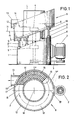
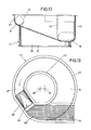
- the vibratory vibratory grinding machine has a machine base frame 1 which is circular in plan with a drive motor 2 fixed on the circumference.
- the flyweight imbalance masses 4, 5, which are designed as disk segments, are set in motion by means of a belt drive 3.
- the machine base 1 has an upper side 6 which is inclined at an acute angle to the horizontal and from which lugs 7 extend in a uniform angular distribution. These serve to support compression springs 8 of approximately the same length, which also carry the vibrating scrubbing container 9 with the interposition of lugs 10.
- the vibrating scouring container 9 has an annular plan.
- the track line S of the container bottom 11 runs in a plane arranged at an acute angle to the horizontal H, namely the angle of inclination alpha is approximately 20 degrees. This plane is also inclined at an acute angle to the axis of the centrifugal weights 4/5.
- the height of the channel side wall 12 extends in the lowest area to above the level of the bottom track line S in the highest area B ', which is also called the highest container apex B' in the following. This is indicated by the horizontal line L.
- the vibrating scrubbing container As a result of such a design of the vibrating scrubbing container, it has a bottom section 11 'which rises from the lowest container beginning B to the highest container apex B' and the bottom section 11 '' which descends from the highest apex B 'to the deepest beginning B. Since the track line S runs in one plane , the angle of rise and fall are the same.
- the contents of the container are conveyed from the lowest beginning B to the highest vertex B 'in the direction of the arrow y by means of the flyweight imbalance masses 4, 5 while carrying out a helical circulation.
- the sloping container section also appears as a processing section with this circulation effect.
- An emptying opening is provided in the lowest area.
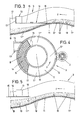
- the vibrating scrubbing container 9 is equipped near the lowest container beginning in the region of the sloping bottom section 11 ′′ with a secant discharge nozzle 13. This is assigned a discharge and separation device 14 which can be displaced concentrically to the container center M in the direction of the highest apex B ′ With regard to the circular ring section, there is a separating screen 15 with the highest apex B 'facing ramp 16. The other end of the separating screen forms a raised end wall 17 which extends flush between the inner and outer walls of the container .
- the separating screen 15 is brought into the position according to FIGS. 4 and 5. Then the contents of the container are conveyed upward in the region of the rising floor section 11 '. After reaching the highest-lying top of the container B ', the contents of the container move through the processing section, which drops continuously to the lowest-lying beginning B, with simultaneous loosening.
- Fig. 5 shows that the contents of the container then run below the separating sieve. It is also illustrated in FIG. 5 that the container content coil has the greatest thickness in the lowest beginning B.
- the separating screen 15 is to be moved into the position illustrated in FIGS. 2 and 3. this can be done by motor or by hand.
- the end 16 of the separating screen 15 facing the conveying direction y abuts the channel bottom 11 just behind the highest end B ', see FIG. 3.
- the end wall 17 of the separating screen 15 extends in extension to the discharge side wall 13'. .
- the container contents therefore reach the separating screen 15.
- the processing bodies 18 fall through while the workpieces 19 are being discharged.
- a tangentially oriented discharge nozzle 20 is provided. This extends above the sloping container bottom 11 ".
- the discharge nozzle 20 guides a discharge slide 21 which is designed as a separating sieve 22. In the discharge position its end 23, which is designed as a ramp and faces the conveying direction y, is placed on the channel bottom shortly behind the highest end B ' 11.
- the separating screen 22 is also provided with a raised wall 24 which, in the discharge position, extends in the extension of the shorter side wall 20 'of the discharge spout 20.
- Another variant, not shown, is that instead of a separating sieve which can be shifted concentrically to the center of the container, the sieve is pushed into the vibrating scraper from above container is used.
- the upper centrifugal weight 4 extends in the interior of the annular vibrating scouring container 9 and the lower centrifugal weight 5 extends in the upper region of the machine base 1.
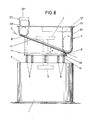
- the cross-sectionally U-shaped vibrating scouring container trough is such that the trough height in the lowest region B of the arched container bottom 11 is approximately twice as large as that in the highest container region B '.
- the gutter height in the highest region B ' corresponds approximately to the gutter width, see FIG. 8.
- the side walls 12 ', 12 "emanating from the container bottom 11 are dimensioned such that they extend in the deepest area to approximately the height of the upper edge of the side walls provided in the highest container area. This means that the upper container edge is arranged on a horizontal plane.
- the gutter side walls 12 ', 12 "of the vibrating scrubbing container 9 are aligned parallel to one another and perpendicularly.
- this vibrating scrubbing container also has a bottom section 11 'which rises from the lowest container beginning B to the highest container area B' and the bottom section 11 '' which slopes from the highest area B 'to the lowest area B Angles of rise and fall are the same.
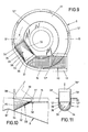
- the scrubbing container trough merges into a straight section 32.
- the cross section of the latter is somewhat enlarged.
- this straight section 32 there is a flap 33, the direction of conveyance of the contents of the container facing end section 34 corresponds to the curvature of the floor of the vibrating scouring container channel in the line 32.
- the edge of the end section 34 is aligned secant to the circular shape of the vibrating scouring box 9, see FIG Horizontal axis of the flap 33 into a plane 36.
- the flap axis adjacent to the plane 36 is formed by a film hinge zone 37, and the flap 33 is fixed beyond the film hinge zone 37 on a transverse web 38 of the vibrating scrubber tray 38 and the film hinge zone 37 run secant to the circular shape of the vibrating scrubber 9.
- the bottom surface of the flap 33 is directed inclined.
- the transverse curvature of the flap continues in upwardly directed side walls 39, which end at the level of the upper edge of the vibration scrubbing container 9 when the flap is in the discharge position.
- the side walls 39 In the area of the end section 34, the side walls 39 continue into webs 39 'projecting into the vibrating scrubbing container 9, which webs are connected to one another by a yoke 39 ".
- a flap actuation device (not shown) can act thereon.
- the flap 33 or the crosspiece 38 is followed by a discharge section 40 which is arranged in a secant shape to the circular shape of the vibration scrubbing container. The latter continues in a discharge spout 13. In the discharge section 40 there is a separating screen 15 located at the level of the crosspiece 38. This or the discharge section 40 is at an obtuse angle to the straight section 32 receiving the flap 33.
- the flap 33 is to be pivoted into the dot-dash position shown in FIG. 10.
- the flap 33 is moved in the downward direction, the curved end portion 34 of which positively engages the bottom surface of the scrubbing container channel.
- the container content coming from the highest region B 'of the container base 11 thus runs onto the flap 33, can continue to move helically there over a certain length and is then passed onto the separating screen 15.
- the machining bodies fall through while the workpieces are being discharged.
- the height of the helix in the lowest area B is approximately twice as large as in the highest area B '.
- the container contents in the highest region B ' reach a higher speed while loosening the container contents.
- the constant change in the cross section of the helix leads to a change in the pressure and speed of the container contents, which results in an increased processing performance.
- the channel width in the deepest area B is larger than in the highest area B ', and in this case there is a ratio of approximately 2: 1.
- the cross-sectional shape of the helix is illustrated in these areas with broken lines in FIG. 12.
- a straight section 32 ′ is also provided behind the highest-lying container area B, which serves to receive a flap 33. This is followed by the discharge section 40 ', which is also secant to the circular ring shape of the Vibrating scrubber 41 runs.
- the gutter side walls 42, 43 are aligned exclusively vertically to one another in this embodiment.
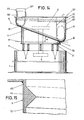
- FIGS. 14 and 15 which largely corresponds to the design illustrated in FIG. 8, the same parts have the same reference numerals.
- g. 8 shows the inner surface of the gutter outer wall 12 'near the upper edge of an annular bead 44 which projects into the interior of the gutter and runs approximately in the horizontal plane and is triangular in cross section. In the exemplary embodiment, this is formed by a material thickening of the container lining 45 made of rubber or suitable plastic.
Landscapes
- Engineering & Computer Science (AREA)
- Mechanical Engineering (AREA)
- Finish Polishing, Edge Sharpening, And Grinding By Specific Grinding Devices (AREA)
- Silver Salt Photography Or Processing Solution Therefor (AREA)
Claims (9)
Priority Applications (5)
| Application Number | Priority Date | Filing Date | Title |
|---|---|---|---|
| AT80106216T ATE2878T1 (de) | 1979-11-17 | 1980-10-13 | Ringtrogfoermiger vibrations-scheuerbehaelter. |
| FR8023240A FR2469246A1 (fr) | 1979-11-17 | 1980-10-30 | Cuve de polissage par roulement sous vibration en forme d'auge annulaire |
| SE8007908A SE435463B (sv) | 1979-11-17 | 1980-11-11 | Av fjedrar i ett maskinstativ uppburen ringtragsformad vibrationsbehallare for ytbehandling av arbetsstycken med hjelp av ett lost, partikelformigt bearbetningsmaterial |
| GB8036299A GB2063118B (en) | 1979-11-17 | 1980-11-12 | Vibrating scouring or grinding container |
| CA000364731A CA1156045A (fr) | 1979-11-17 | 1980-11-14 | Dispositif a canal tubulaire vibratoire pour le traitement par abrasion |
Applications Claiming Priority (4)
| Application Number | Priority Date | Filing Date | Title |
|---|---|---|---|
| DE19792946538 DE2946538C2 (de) | 1979-11-17 | 1979-11-17 | Ringtrogförmiger Vibrations-Scheuerbehälter |
| DE2946538 | 1979-11-17 | ||
| DE19803024982 DE3024982A1 (de) | 1980-07-02 | 1980-07-02 | Ringtrogfoermiger vibrations- scheuerbehaelter |
| DE3024982 | 1980-07-02 |
Publications (2)
| Publication Number | Publication Date |
|---|---|
| EP0029897A1 EP0029897A1 (fr) | 1981-06-10 |
| EP0029897B1 true EP0029897B1 (fr) | 1983-03-30 |
Family
ID=25782036
Family Applications (1)
| Application Number | Title | Priority Date | Filing Date |
|---|---|---|---|
| EP80106216A Expired EP0029897B1 (fr) | 1979-11-17 | 1980-10-13 | Cuve de polissage annulaire vibrante |
Country Status (3)
| Country | Link |
|---|---|
| US (1) | US4428161A (fr) |
| EP (1) | EP0029897B1 (fr) |
| DE (1) | DE3062547D1 (fr) |
Families Citing this family (8)
| Publication number | Priority date | Publication date | Assignee | Title |
|---|---|---|---|---|
| US4520598A (en) * | 1982-08-13 | 1985-06-04 | Jepmar | Bowl-type vibratory finishing machine |
| US4693037A (en) * | 1986-02-25 | 1987-09-15 | Roto-Finish Company, Inc. | Multistage finishing device and method |
| IT238331Y1 (it) * | 1997-05-30 | 2000-10-16 | Hyppocampus Srl | Macchina per trattamenti di asciugatura,lucidatura e rigenerazione diposate ed oggetti metallici da tavola |
| US6261154B1 (en) | 1998-08-25 | 2001-07-17 | Mceneny Jeffrey William | Method and apparatus for media finishing |
| ES2178495T3 (es) * | 1998-11-14 | 2002-12-16 | Mtu Aero Engines Gmbh | Sistema de mecanizacion de precision de piezas componentes simetricas rotativas. |
| US6837180B2 (en) * | 2001-05-07 | 2005-01-04 | Ron Billi | Animal waste receptacle having vibration directed flow |
| ITBS20010084U1 (it) * | 2001-10-18 | 2003-04-18 | Hyppocampus Srl | Macchina per asiugare, lucidare e rigenerare posate e articoli metallici da tavola |
| US9042425B2 (en) * | 2011-02-18 | 2015-05-26 | Leco Corporation | Vacuum cleaning structure for electrode furnace |
Family Cites Families (11)
| Publication number | Priority date | Publication date | Assignee | Title |
|---|---|---|---|---|
| GB1240111A (en) * | 1968-01-08 | 1971-07-21 | Lucas Industries Ltd | Ignition distributors |
| CH492518A (de) * | 1968-05-27 | 1970-06-30 | Huber Ernst | Maschine zum Entgraten, Polieren, Mischen und Mahlen |
| JPS5140316B1 (fr) * | 1970-07-08 | 1976-11-02 | ||
| US3771266A (en) * | 1970-07-08 | 1973-11-13 | H Kobayashi | Vibratory finishing apparatus with a helical and tubular container |
| FR2178388A5 (fr) * | 1972-03-30 | 1973-11-09 | Roto Finish Sarl | |
| FR2178387A5 (fr) | 1972-03-30 | 1973-11-09 | Roto Finish Sarl | |
| DE2346704A1 (de) | 1973-09-17 | 1975-03-20 | Walther Carl Kurt Fa | Verfahren zur oberflaechenbearbeitung von werkstuecken nebst vorrichtung und behandlungsmittel hierzu |
| CH584090A5 (fr) * | 1974-05-24 | 1977-01-31 | Walther Carl Kurt Fa | |
| DE2425095C3 (de) * | 1974-05-24 | 1978-03-16 | Carl Kurt Walther Gmbh & Co Kg, 5600 Wuppertal | Vibrations-Scheuerbehälter |
| DE2425094C3 (de) | 1974-05-24 | 1984-07-05 | Carl Kurt Walther Gmbh & Co Kg, 5600 Wuppertal | Federnd abgestützter Ringtrog- Vibrations-Scheuerbehälter |
| FR2419802A1 (fr) * | 1978-03-13 | 1979-10-12 | Parker Ste Continentale | Machine de finition vibrante |
-
1980
- 1980-10-13 EP EP80106216A patent/EP0029897B1/fr not_active Expired
- 1980-10-13 DE DE8080106216T patent/DE3062547D1/de not_active Expired
- 1980-11-14 US US06/206,926 patent/US4428161A/en not_active Expired - Lifetime
Also Published As
| Publication number | Publication date |
|---|---|
| US4428161A (en) | 1984-01-31 |
| DE3062547D1 (en) | 1983-05-05 |
| EP0029897A1 (fr) | 1981-06-10 |
Similar Documents
| Publication | Publication Date | Title |
|---|---|---|
| DE68909940T2 (de) | Vorrichtung zum evakuieren, fördern, verdichten und entleeren von schüttgut, insbesondere von spänen und schrott. | |
| DE3206544C2 (fr) | ||
| DE202019105728U1 (de) | Siebvorrichtung zum Sortieren von Siedlungsabfall | |
| WO1993000489A1 (fr) | Dessableur long pour la separation et l'evacuation de sable de canaux d'amenee, notamment de stations d'epuration | |
| DE19523705A1 (de) | Siebvorrichtung zur Trennung eines Sand-/Kies-Materials in gröbere und feinere Bestandteile | |
| DE4014226A1 (de) | In vibration versetzbarer lagerbehaelter mit inneren leitflaechen und niedrigem bodenprofil | |
| DE1652173A1 (de) | Vibrations-Schleifmuehle | |
| DE2946538C2 (de) | Ringtrogförmiger Vibrations-Scheuerbehälter | |
| EP0029897A1 (fr) | Cuve de polissage annulaire vibrante | |
| EP0265669A2 (fr) | Machine à trier | |
| EP0220699B1 (fr) | Véhicule d'alimentation pour une accumulation de cages en plusieurs étages | |
| EP0370237B1 (fr) | Dispositif d'élimination par lavage et de tri d'impuretés organiques, argileuses et similaires dans des matières solides à gros grains et à grains fins amenées en continu | |
| EP3760322B1 (fr) | Dispositif de transport de dosage destiné au transport et au dosage d'un mélange solide | |
| EP0434995B1 (fr) | Silo équipé d'un dispositif d'évacuation | |
| DE20320988U1 (de) | Fördervorrichtung für Backwaren | |
| DE3228658C2 (de) | Fliehkraft-Gleitschleifmaschine | |
| DE69402686T2 (de) | Zentrifuge für schüttgut | |
| DE19738676C1 (de) | Vorrichtung zum Auswaschen und Sortieren von organischen lehmartigen und sonstigen Verunreinigungen aus fortlaufend zugeführten grob- und feinkörnigen Feststoffen | |
| DE2425095C3 (de) | Vibrations-Scheuerbehälter | |
| DE2603127C2 (de) | Vibrationsgleitschleifmaschine | |
| DE3024982A1 (de) | Ringtrogfoermiger vibrations- scheuerbehaelter | |
| CH427549A (de) | Kontinuierlich arbeitende Maschine zur Oberflächenbearbeitung von Werkstücken | |
| DE9014270U1 (de) | Silo mit einer Austragvorrichtung | |
| DE4244421A1 (de) | Schnecken-Zentrifuge | |
| DE4434635A1 (de) | Feinstkohlentrockenklassierer mit Reingigungssystem |
Legal Events
| Date | Code | Title | Description |
|---|---|---|---|
| PUAI | Public reference made under article 153(3) epc to a published international application that has entered the european phase |
Free format text: ORIGINAL CODE: 0009012 |
|
| AK | Designated contracting states |
Designated state(s): AT CH DE IT NL |
|
| 17P | Request for examination filed |
Effective date: 19810512 |
|
| ITF | It: translation for a ep patent filed | ||
| GRAA | (expected) grant |
Free format text: ORIGINAL CODE: 0009210 |
|
| AK | Designated contracting states |
Designated state(s): AT CH DE IT LI NL |
|
| REF | Corresponds to: |
Ref document number: 2878 Country of ref document: AT Date of ref document: 19830415 Kind code of ref document: T |
|
| REF | Corresponds to: |
Ref document number: 3062547 Country of ref document: DE Date of ref document: 19830505 |
|
| PGFP | Annual fee paid to national office [announced via postgrant information from national office to epo] |
Ref country code: CH Payment date: 19840925 Year of fee payment: 5 |
|
| PGFP | Annual fee paid to national office [announced via postgrant information from national office to epo] |
Ref country code: DE Payment date: 19841011 Year of fee payment: 5 |
|
| PGFP | Annual fee paid to national office [announced via postgrant information from national office to epo] |
Ref country code: NL Payment date: 19841031 Year of fee payment: 5 |
|
| PG25 | Lapsed in a contracting state [announced via postgrant information from national office to epo] |
Ref country code: NL Effective date: 19860501 |
|
| NLV4 | Nl: lapsed or anulled due to non-payment of the annual fee | ||
| PGFP | Annual fee paid to national office [announced via postgrant information from national office to epo] |
Ref country code: AT Payment date: 19861015 Year of fee payment: 7 |
|
| PG25 | Lapsed in a contracting state [announced via postgrant information from national office to epo] |
Ref country code: AT Effective date: 19871013 |
|
| PG25 | Lapsed in a contracting state [announced via postgrant information from national office to epo] |
Ref country code: LI Effective date: 19871031 Ref country code: CH Effective date: 19871031 |
|
| REG | Reference to a national code |
Ref country code: CH Ref legal event code: PL |
|
| PG25 | Lapsed in a contracting state [announced via postgrant information from national office to epo] |
Ref country code: DE Effective date: 19880701 |
|
| PLBE | No opposition filed within time limit |
Free format text: ORIGINAL CODE: 0009261 |
|
| STAA | Information on the status of an ep patent application or granted ep patent |
Free format text: STATUS: NO OPPOSITION FILED WITHIN TIME LIMIT |