EP0030159A2 - Farbbild-Wiedergabegerät - Google Patents
Farbbild-Wiedergabegerät Download PDFInfo
- Publication number
- EP0030159A2 EP0030159A2 EP80304346A EP80304346A EP0030159A2 EP 0030159 A2 EP0030159 A2 EP 0030159A2 EP 80304346 A EP80304346 A EP 80304346A EP 80304346 A EP80304346 A EP 80304346A EP 0030159 A2 EP0030159 A2 EP 0030159A2
- Authority
- EP
- European Patent Office
- Prior art keywords
- light
- emitting elements
- elements
- red
- green
- Prior art date
- Legal status (The legal status is an assumption and is not a legal conclusion. Google has not performed a legal analysis and makes no representation as to the accuracy of the status listed.)
- Granted
Links
Images


Classifications
-
- H—ELECTRICITY
- H04—ELECTRIC COMMUNICATION TECHNIQUE
- H04N—PICTORIAL COMMUNICATION, e.g. TELEVISION
- H04N9/00—Details of colour television systems
- H04N9/12—Picture reproducers
- H04N9/30—Picture reproducers using solid-state colour display devices
-
- G—PHYSICS
- G09—EDUCATION; CRYPTOGRAPHY; DISPLAY; ADVERTISING; SEALS
- G09F—DISPLAYING; ADVERTISING; SIGNS; LABELS OR NAME-PLATES; SEALS
- G09F13/00—Illuminated signs; Luminous advertising
- G09F13/26—Signs formed by electric discharge tubes
-
- H—ELECTRICITY
- H04—ELECTRIC COMMUNICATION TECHNIQUE
- H04N—PICTORIAL COMMUNICATION, e.g. TELEVISION
- H04N9/00—Details of colour television systems
- H04N9/12—Picture reproducers
- H04N9/16—Picture reproducers using cathode ray tubes
Definitions
- the present invention relates to apparatus for displaying coloured images having a display surface constructed from a number of light-emitting elements each of which emits light in one of three primary colours of red, green and blue (hereinafter denoted as "R", “G” and “B", respectively where appriate). More particularly, the invention relates to such apparatus having an arrangement of light-emitting elements in which the resolution, colour mixing, and brightness of the display area are significantly improved. The invention is particularly applicable to such apparatus in which the display surface is large for example more than 30m 2 in area.
- Conventional colour image display apparatuses include a large number of picture elements, each picture element being made up of individual light-emitting elements which emit light in the three primary colours.
- each picture element is constituted by arranging in combination three light-emitting elements, namely a red light-emitting element, a green light-emitting element and a blue light-emitting element.
- the spacing or pitch between the light-emitting elements has a lower limit due to inherent structural requirements of the display surface and the light-emitting elements themselves.
- the total number of elements has an upper limit due to economic reasons. Accordingly, the conventional apparatuses are not always always satisfactory as to the quality of displayed image. For instance, the primary colours provided by the individual light-emitting elements are often observable separately from one another and the brightness of the displayed image is often insufficient.
- Figure I shows conventional arrangement of light-emitting elements for a display apparatus which produces what is considered to be the most excellent display quality among previously known arrangements.
- reference characters lR, lG and 1B designate light-emitting elements of the three primary colours respectively
- reference numberal 2 denotes the display surface of the apparatus.
- the light-emitting elements are selected for energisation by means of column and row selecting lines (not shown) and are driven by corresponding video signals. More particularly, the colour video signals are sampled and applied to the light-emitting elements corresponding to their positions so that they emit light at brightness corresponding to the signal amplitude.
- the light-emitting elements in each row are arranged at a pitch of P 0 in the order R, G, B R, G, ..., so that the horizontal pitch of light-emitting elements of the same colour is 3P 0 .
- The.pitch P' 1 of the rows is usally set to a value which is close to the value P 1 .
- P' 1 P 1 .
- the equivalent sampling pitch of the displayed image in the horizontal direction can be regarded as the shortest distance in the horizontal direction between light-emitting elements of the same colour.
- the resolution of the display image is mainly governed by the equivalent sampling pitch of the green light-emitting elements because the human eye is most sensitive to and has its highest resolution for wavelengths around that of green light and is less sensitive to red and blue light.
- the red and blue light-emitting elements are necessary for colour reproduction.
- the red (R) element on the edge of the figure is spaced by about 1.5P 0 from the green (G) element with which the light from the red element should be mixed.
- the green (G) element with which the light from the red element should be mixed.
- an object of the present invention is to provide apparatus for displaying coloured images which provides improved resolution, improved colour mixing and higher maximum brightness compared with conventional apparatuses, by taking into account the visual response of the human eye and the light emission characteristics of the light-emitting elements.
- the present invertion provides apparatus for displaying coloured images, comprising a display surface divided into a plurality of picture elements each of which can emit red, green and blue light, each picture element consisting of one red light-emitting element, two green light-emitting elements and one blue light-emitting element.
- apparatus for displaying coloured images comprising a plurality of red -, green - and blue light emitting elements forming a display surface,wherein there are twice as many green light-emitting elements as the number of red - or blue light-emitting elements.
- green CRT elements are arranged in the form of a lattice at a pitch P 2 in both column and row directions, while red CRT elements and blue CRT elements are alternately arranged at the cnetres of lattice squares having green CRT elements at their corners.
- P O The smallest separation between adjacent CRT elements, which is in the oblique direction, is denoted by P O .
- Colour video signals are sampled and applied to the CRT elements corresponding to their positions so that they emit light at brightness corresponding to the the signal amplitudes and the desired image is displayed.
- control is so effected that the red and blue CRT elements emit light at a brightness twice that of the brightnesses in the conventional arrangement of Figure 1.
- the resolution of the displayed image is determined mainly by the pitch of the green CRT elements because the resolving power of the human eye is hightest in resolution for wavelengths around that of green light.
- the pitch of the CRT elements has a lower limit.
- the pitches P l and P 2 are approximately equal.
- the pitch in the oblique direction of the image is 1.5 x ⁇ 2P 0 in Figure 1 and P 0 in Figure 4. Accordingly, the arrangement of Figure 4 produces a significantly improved image having higher resolution than that of Figure 1.
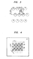
- Fig. 5 is illustrates a display in an edge portion of an image produced by the apparatus shown in Fig. 4.
- a white figure such as a character
- the edge of a white figure is positioned as indicated by the double chain-dotted line, the area to the left of the line being white while the area to the right thereof is black.
- the red CRT element at the end of the figure is spaced by about 1.5P 0 from the green CRT element with which its light is to be mixed, while it is spaced by P 0 in the case of Fig. 5.
- P 0 in the case of Fig. 5.
- colour mixing occurs more readily in the arrangement of Fig. 4 than with the arrangement of Fig. 1. thus improving the quality of the displayed image even at the edge portions : thereof.
- the width of the line should cover at least two rows of CRT elements, With the arrangment of Fig. 1, this means that the width of the line should be at least 1.5P 0 , whereas with the arrangement of Fig. 4 it needs only to be P 0 / ⁇ 2 as will be apparent from Fig. 6. This is applicable also to a line image extending vertically: whereas, in the arrangement of Fig. 1, the line width should be at least P o , in the arrangement of Fig. 4 it need only be P 0 / ⁇ 2.
- the arrangement of Fig. 4 produces the greater brightness with Î/Î G > 4/3.
- the green fluorescent material provides the lowest maximum output while the red and blue fluorescent materials can produce a much greater maximum output.
- the linearity of light emission output with beam current may be disregarded. Therefore, the maximum outputs of the CRT elements are determined primarily from service life factors.
- Fig. 7 shows another embodiment of the invention in which the CRT elements are arranged at a pitch P O . More specifically, red CRT elements and green CRT elements are alternately arranged in the order of R, G, R, G, R, ... in even numbered rows, while green CRT elements and blue CRT elements are arranged in the order of G, B, G, B, G,... in odd numbered rows. Furthermore, the arrangement is such that the greenCRT elements and the blue CRT elements in odd numbered rows are immediately below the red CRT elements and the green CRT elements in even numbered rows, respectively.
- the equivalent sampling pitch in the horizontal direction which determines the resolution of the displayed image is the shortest distance between the green elements in the horizontal direction.
- the equivalent sampling pitch P in Fig. 1 is equal to 1.5P 0 while in Fig. 7 the equivalent sampling pitch P 2 is equal to P O .
- the total number of CRT elements is limited by the pitch of the elements d ue to structural limitations of the elements
- CRT elements emitting light in three primary colours of red, green and blue are arranged as shown in Fig. 4 or Fig. 7, thereby obtaining more resolution, better colour mixing, higher maximum brightness and significantly improved display quality compared with conventional apparatuses.
Landscapes
- Engineering & Computer Science (AREA)
- Multimedia (AREA)
- Signal Processing (AREA)
- Physics & Mathematics (AREA)
- General Physics & Mathematics (AREA)
- Theoretical Computer Science (AREA)
- Devices For Indicating Variable Information By Combining Individual Elements (AREA)
- Video Image Reproduction Devices For Color Tv Systems (AREA)
Applications Claiming Priority (4)
| Application Number | Priority Date | Filing Date | Title |
|---|---|---|---|
| JP158815/79 | 1979-12-04 | ||
| JP158814/79 | 1979-12-04 | ||
| JP15881479A JPS5680081A (en) | 1979-12-04 | 1979-12-04 | Color display with large screen |
| JP15881579A JPS5680082A (en) | 1979-12-04 | 1979-12-04 | Color display with large screen |
Publications (3)
| Publication Number | Publication Date |
|---|---|
| EP0030159A2 true EP0030159A2 (de) | 1981-06-10 |
| EP0030159A3 EP0030159A3 (en) | 1981-07-01 |
| EP0030159B1 EP0030159B1 (de) | 1984-12-12 |
Family
ID=26485814
Family Applications (1)
| Application Number | Title | Priority Date | Filing Date |
|---|---|---|---|
| EP80304346A Expired EP0030159B1 (de) | 1979-12-04 | 1980-12-03 | Farbbild-Wiedergabegerät |
Country Status (5)
| Country | Link |
|---|---|
| US (1) | US4491863A (de) |
| EP (1) | EP0030159B1 (de) |
| AU (1) | AU544556B2 (de) |
| DE (1) | DE3069810D1 (de) |
| HK (1) | HK39785A (de) |
Cited By (6)
| Publication number | Priority date | Publication date | Assignee | Title |
|---|---|---|---|---|
| FR2574206A1 (fr) * | 1984-12-05 | 1986-06-06 | Delcourt Michel | Cellule emettrice de lumiere, de luminance et de chromatismes variables et ecran obtenu par la juxtaposition d'une pluralite de cellules emettrices |
| US4725828A (en) * | 1984-02-15 | 1988-02-16 | International Business Machines Corporation | Color display apparatus and method of coding a color image |
| US4890097A (en) * | 1984-11-16 | 1989-12-26 | Matsushita Electric Industrial Co., Ltd. | Active matrix circuit for liquid crystal displays |
| EP0454538A1 (de) * | 1990-04-27 | 1991-10-30 | Thomson-Lcd | Matrix-Farbbildschirm mit Zeilensprungadressierung |
| DE4023081A1 (de) * | 1990-07-20 | 1992-01-23 | Ottmar Haberkern | Bildplatte fuer blend- und stoerungsfreie farbbildwiedergabe |
| WO1994023532A1 (en) * | 1993-04-05 | 1994-10-13 | Antti Aarni Tapani Iivanainen | Improving spatiotemporal resolution and enhancing motion by interlacing |
Families Citing this family (33)
| Publication number | Priority date | Publication date | Assignee | Title |
|---|---|---|---|---|
| JPS59111196A (ja) * | 1982-12-15 | 1984-06-27 | シチズン時計株式会社 | カラ−表示装置 |
| JPS60120398A (ja) * | 1983-12-02 | 1985-06-27 | シチズン時計株式会社 | マトリクス形カラー表示装置の駆動方法 |
| JPS60162293A (ja) * | 1984-02-02 | 1985-08-24 | ソニー株式会社 | 表示装置 |
| US4920409A (en) * | 1987-06-23 | 1990-04-24 | Casio Computer Co., Ltd. | Matrix type color liquid crystal display device |
| US4991122A (en) * | 1987-10-07 | 1991-02-05 | General Parametrics Corporation | Weighted mapping of color value information onto a display screen |
| US4892391A (en) * | 1988-02-16 | 1990-01-09 | General Electric Company | Method of arranging the cells within the pixels of a color alpha-numeric display device |
| GB8908322D0 (en) * | 1989-04-13 | 1989-06-01 | Stellar Communicat Ltd | Display |
| US5724062A (en) * | 1992-08-05 | 1998-03-03 | Cree Research, Inc. | High resolution, high brightness light emitting diode display and method and producing the same |
| US6932477B2 (en) * | 2001-12-21 | 2005-08-23 | Koninklijke Philips Electronics N.V. | Apparatus for providing multi-spectral light for an image projection system |
| US7417648B2 (en) * | 2002-01-07 | 2008-08-26 | Samsung Electronics Co. Ltd., | Color flat panel display sub-pixel arrangements and layouts for sub-pixel rendering with split blue sub-pixels |
| CN1682336A (zh) * | 2002-09-13 | 2005-10-12 | 皇家飞利浦电子股份有限公司 | 具有提高垂直分辩率的crt |
| KR101095637B1 (ko) * | 2004-09-23 | 2011-12-19 | 삼성전자주식회사 | 광 발생 장치, 이를 갖는 백라이트 어셈블리 및 백라이트어셈블리를 갖는 표시장치 |
| KR101189085B1 (ko) * | 2005-07-14 | 2012-11-09 | 삼성디스플레이 주식회사 | 백라이트 유닛과 이를 포함하는 액정표시장치 |
| KR100780223B1 (ko) * | 2006-01-10 | 2007-11-27 | 삼성전기주식회사 | 색 얼룩 향상을 위한 led 면 광원 및 이를 구비하는lcd 백라이트 유닛 |
| DE102007041193A1 (de) * | 2007-08-31 | 2009-03-05 | Osram Gesellschaft mit beschränkter Haftung | Leuchtmodul für eine Beleuchtungseinrichtung und Beleuchtungseinrichtung |
| KR101615332B1 (ko) | 2012-03-06 | 2016-04-26 | 삼성디스플레이 주식회사 | 유기 발광 표시 장치의 화소 배열 구조 |
| US10832616B2 (en) | 2012-03-06 | 2020-11-10 | Samsung Display Co., Ltd. | Pixel arrangement structure for organic light emitting diode display |
| KR102063973B1 (ko) | 2012-09-12 | 2020-01-09 | 삼성디스플레이 주식회사 | 유기전계발광 표시장치 및 그의 구동방법 |
| US11264430B2 (en) | 2016-02-18 | 2022-03-01 | Chengdu Boe Optoelectronics Technology Co., Ltd. | Pixel arrangement structure with misaligned repeating units, display substrate, display apparatus and method of fabrication thereof |
| CN110134353B (zh) | 2018-02-09 | 2021-04-27 | 京东方科技集团股份有限公司 | 颜色补偿方法、补偿装置以及显示装置 |
| CN110133899A (zh) | 2018-02-09 | 2019-08-16 | 京东方科技集团股份有限公司 | 像素排列结构、显示基板、显示装置 |
| US11747531B2 (en) | 2016-02-18 | 2023-09-05 | Chengdu Boe Optoelectronics Technology Co., Ltd. | Display substrate, fine metal mask set and manufacturing method thereof |
| CN110137213B (zh) | 2018-02-09 | 2025-03-25 | 京东方科技集团股份有限公司 | 像素排列结构及其显示方法、显示基板 |
| WO2021016946A1 (zh) | 2019-07-31 | 2021-02-04 | 京东方科技集团股份有限公司 | 显示基板及其制备方法、显示面板、显示装置 |
| US10854684B2 (en) | 2016-02-18 | 2020-12-01 | Boe Technology Group Co., Ltd. | Pixel arrangement structure and driving method thereof, display substrate and display device |
| CN110137215B (zh) | 2018-02-09 | 2025-01-14 | 京东方科技集团股份有限公司 | 像素排列结构、显示基板和显示装置 |
| US11448807B2 (en) | 2016-02-18 | 2022-09-20 | Chengdu Boe Optoelectronics Technology Co., Ltd. | Display substrate, fine metal mask set and manufacturing method thereof |
| US11233096B2 (en) | 2016-02-18 | 2022-01-25 | Boe Technology Group Co., Ltd. | Pixel arrangement structure and driving method thereof, display substrate and display device |
| US11574960B2 (en) | 2018-02-09 | 2023-02-07 | Boe Technology Group Co., Ltd. | Pixel arrangement structure, display substrate, display device and mask plate group |
| CN110137209A (zh) * | 2018-02-09 | 2019-08-16 | 京东方科技集团股份有限公司 | 一种像素排布结构、高精度金属掩模板及显示装置 |
| CN114994973B (zh) | 2018-02-09 | 2023-04-28 | 京东方科技集团股份有限公司 | 显示基板和显示装置 |
| CN113823240B (zh) | 2018-12-13 | 2023-04-18 | 京东方科技集团股份有限公司 | 显示装置 |
| CN112673476B (zh) | 2019-07-31 | 2025-12-30 | 京东方科技集团股份有限公司 | 显示基板和显示装置 |
Family Cites Families (8)
| Publication number | Priority date | Publication date | Assignee | Title |
|---|---|---|---|---|
| US3456069A (en) * | 1966-03-30 | 1969-07-15 | Bell & Howell Co | Color synchronization for two color per line television systems |
| US3624273A (en) * | 1968-11-22 | 1971-11-30 | Alfred J Gale | Flat screen display devices using an array of charged particle sources |
| NL7018169A (de) * | 1970-03-09 | 1971-09-13 | ||
| JPS5018135A (de) * | 1973-06-20 | 1975-02-26 | ||
| US3909525A (en) * | 1973-12-10 | 1975-09-30 | Rockwell International Corp | Display system optics |
| US3961365A (en) * | 1974-10-24 | 1976-06-01 | Stewart-Warner Corporation | Color display device |
| US4047203A (en) * | 1976-05-12 | 1977-09-06 | Eastman Kodak Company | Color imaging array |
| JPS5379434A (en) * | 1976-12-24 | 1978-07-13 | Hitachi Ltd | Solid state color pickup device |
-
1980
- 1980-12-03 EP EP80304346A patent/EP0030159B1/de not_active Expired
- 1980-12-03 DE DE8080304346T patent/DE3069810D1/de not_active Expired
- 1980-12-03 US US06/212,378 patent/US4491863A/en not_active Expired - Lifetime
- 1980-12-03 AU AU65024/80A patent/AU544556B2/en not_active Expired
-
1985
- 1985-05-23 HK HK397/85A patent/HK39785A/en not_active IP Right Cessation
Cited By (7)
| Publication number | Priority date | Publication date | Assignee | Title |
|---|---|---|---|---|
| US4725828A (en) * | 1984-02-15 | 1988-02-16 | International Business Machines Corporation | Color display apparatus and method of coding a color image |
| US4890097A (en) * | 1984-11-16 | 1989-12-26 | Matsushita Electric Industrial Co., Ltd. | Active matrix circuit for liquid crystal displays |
| FR2574206A1 (fr) * | 1984-12-05 | 1986-06-06 | Delcourt Michel | Cellule emettrice de lumiere, de luminance et de chromatismes variables et ecran obtenu par la juxtaposition d'une pluralite de cellules emettrices |
| EP0454538A1 (de) * | 1990-04-27 | 1991-10-30 | Thomson-Lcd | Matrix-Farbbildschirm mit Zeilensprungadressierung |
| FR2661586A1 (fr) * | 1990-04-27 | 1991-10-31 | Thomson Lcd | Ecran matriciel couleurs a adressage entrelace. |
| DE4023081A1 (de) * | 1990-07-20 | 1992-01-23 | Ottmar Haberkern | Bildplatte fuer blend- und stoerungsfreie farbbildwiedergabe |
| WO1994023532A1 (en) * | 1993-04-05 | 1994-10-13 | Antti Aarni Tapani Iivanainen | Improving spatiotemporal resolution and enhancing motion by interlacing |
Also Published As
| Publication number | Publication date |
|---|---|
| HK39785A (en) | 1985-05-31 |
| EP0030159B1 (de) | 1984-12-12 |
| AU6502480A (en) | 1981-06-11 |
| AU544556B2 (en) | 1985-06-06 |
| DE3069810D1 (en) | 1985-01-24 |
| US4491863A (en) | 1985-01-01 |
| EP0030159A3 (en) | 1981-07-01 |
Similar Documents
| Publication | Publication Date | Title |
|---|---|---|
| EP0030159A2 (de) | Farbbild-Wiedergabegerät | |
| US5057739A (en) | Matrix array of cathode ray tubes display device | |
| US6072272A (en) | Color flat panel display device | |
| EP0226423B1 (de) | Farbbildröhre | |
| IE36877B1 (en) | Cathode ray tube construction | |
| US5036247A (en) | Dot matrix fluorescent display device | |
| KR930006835B1 (ko) | 형광표시장치 | |
| US4935670A (en) | Image display device | |
| KR930007170B1 (ko) | 비데오 표시장치 | |
| US2702873A (en) | Screen structure for color television cathode-ray tubes | |
| EP0387911A2 (de) | CRT-Matrixtyp-Videosichtgerät | |
| JP2555019B2 (ja) | 蛍光表示管の駆動方法 | |
| JPH0135463B2 (de) | ||
| JPS59134537A (ja) | カラ−映像管 | |
| EP0467304B1 (de) | Bildbetrachtungsgerät | |
| JPS58102444A (ja) | 平面カラ−「けい」光表示管 | |
| JPH10154469A (ja) | カラー表示方法 | |
| JPS59134534A (ja) | 映像管 | |
| JPH0513018A (ja) | 画像表示装置 | |
| JPS5999648A (ja) | 平板形陰極線管 | |
| JPH053105B2 (de) | ||
| JPH0576128B2 (de) | ||
| JPS60115135A (ja) | 平板形陰極線管 | |
| GB2147733A (en) | Flat hybrid multiplexed colour 1250 line TV display system with 3D and micro display | |
| JPH02100247A (ja) | 画像表示装置 |
Legal Events
| Date | Code | Title | Description |
|---|---|---|---|
| PUAI | Public reference made under article 153(3) epc to a published international application that has entered the european phase |
Free format text: ORIGINAL CODE: 0009012 |
|
| PUAL | Search report despatched |
Free format text: ORIGINAL CODE: 0009013 |
|
| AK | Designated contracting states |
Designated state(s): DE FR GB |
|
| AK | Designated contracting states |
Designated state(s): DE FR GB |
|
| 17P | Request for examination filed |
Effective date: 19811029 |
|
| DET | De: translation of patent claims | ||
| GRAA | (expected) grant |
Free format text: ORIGINAL CODE: 0009210 |
|
| AK | Designated contracting states |
Designated state(s): DE FR GB |
|
| REF | Corresponds to: |
Ref document number: 3069810 Country of ref document: DE Date of ref document: 19850124 |
|
| ET | Fr: translation filed | ||
| PLBE | No opposition filed within time limit |
Free format text: ORIGINAL CODE: 0009261 |
|
| STAA | Information on the status of an ep patent application or granted ep patent |
Free format text: STATUS: NO OPPOSITION FILED WITHIN TIME LIMIT |
|
| 26N | No opposition filed | ||
| REG | Reference to a national code |
Ref country code: GB Ref legal event code: 746 Effective date: 19960611 |
|
| REG | Reference to a national code |
Ref country code: FR Ref legal event code: D6 |
|
| PGFP | Annual fee paid to national office [announced via postgrant information from national office to epo] |
Ref country code: GB Payment date: 19991201 Year of fee payment: 20 |
|
| PGFP | Annual fee paid to national office [announced via postgrant information from national office to epo] |
Ref country code: DE Payment date: 19991207 Year of fee payment: 20 |
|
| PGFP | Annual fee paid to national office [announced via postgrant information from national office to epo] |
Ref country code: FR Payment date: 19991208 Year of fee payment: 20 |
|
| PG25 | Lapsed in a contracting state [announced via postgrant information from national office to epo] |
Ref country code: GB Free format text: LAPSE BECAUSE OF EXPIRATION OF PROTECTION Effective date: 20001202 |
|
| REG | Reference to a national code |
Ref country code: GB Ref legal event code: PE20 Effective date: 20001202 |