EP0030165B1 - Selbstzentrierendes Kupplungsausrücklager - Google Patents
Selbstzentrierendes Kupplungsausrücklager Download PDFInfo
- Publication number
- EP0030165B1 EP0030165B1 EP80401346A EP80401346A EP0030165B1 EP 0030165 B1 EP0030165 B1 EP 0030165B1 EP 80401346 A EP80401346 A EP 80401346A EP 80401346 A EP80401346 A EP 80401346A EP 0030165 B1 EP0030165 B1 EP 0030165B1
- Authority
- EP
- European Patent Office
- Prior art keywords
- ring
- bearing
- support
- clip
- self
- Prior art date
- Legal status (The legal status is an assumption and is not a legal conclusion. Google has not performed a legal analysis and makes no representation as to the accuracy of the status listed.)
- Expired
Links
- 238000005096 rolling process Methods 0.000 claims description 5
- 238000000034 method Methods 0.000 claims description 3
- 230000008878 coupling Effects 0.000 claims 6
- 238000010168 coupling process Methods 0.000 claims 6
- 238000005859 coupling reaction Methods 0.000 claims 6
- 210000000056 organ Anatomy 0.000 claims 2
- 238000006073 displacement reaction Methods 0.000 description 3
- 239000002184 metal Substances 0.000 description 2
- 229910052751 metal Inorganic materials 0.000 description 2
- 230000002730 additional effect Effects 0.000 description 1
- 238000013016 damping Methods 0.000 description 1
- 230000000694 effects Effects 0.000 description 1
- 230000014759 maintenance of location Effects 0.000 description 1
- 229920002994 synthetic fiber Polymers 0.000 description 1
Images

Classifications
-
- F—MECHANICAL ENGINEERING; LIGHTING; HEATING; WEAPONS; BLASTING
- F16—ENGINEERING ELEMENTS AND UNITS; GENERAL MEASURES FOR PRODUCING AND MAINTAINING EFFECTIVE FUNCTIONING OF MACHINES OR INSTALLATIONS; THERMAL INSULATION IN GENERAL
- F16D—COUPLINGS FOR TRANSMITTING ROTATION; CLUTCHES; BRAKES
- F16D23/00—Details of mechanically-actuated clutches not specific for one distinct type
- F16D23/12—Mechanical clutch-actuating mechanisms arranged outside the clutch as such
- F16D23/14—Clutch-actuating sleeves or bearings; Actuating members directly connected to clutch-actuating sleeves or bearings
-
- F—MECHANICAL ENGINEERING; LIGHTING; HEATING; WEAPONS; BLASTING
- F16—ENGINEERING ELEMENTS AND UNITS; GENERAL MEASURES FOR PRODUCING AND MAINTAINING EFFECTIVE FUNCTIONING OF MACHINES OR INSTALLATIONS; THERMAL INSULATION IN GENERAL
- F16C—SHAFTS; FLEXIBLE SHAFTS; ELEMENTS OR CRANKSHAFT MECHANISMS; ROTARY BODIES OTHER THAN GEARING ELEMENTS; BEARINGS
- F16C19/00—Bearings with rolling contact, for exclusively rotary movement
- F16C19/02—Bearings with rolling contact, for exclusively rotary movement with bearing balls essentially of the same size in one or more circular rows
- F16C19/14—Bearings with rolling contact, for exclusively rotary movement with bearing balls essentially of the same size in one or more circular rows for both radial and axial load
- F16C19/16—Bearings with rolling contact, for exclusively rotary movement with bearing balls essentially of the same size in one or more circular rows for both radial and axial load with a single row of balls
- F16C19/163—Bearings with rolling contact, for exclusively rotary movement with bearing balls essentially of the same size in one or more circular rows for both radial and axial load with a single row of balls with angular contact
-
- F—MECHANICAL ENGINEERING; LIGHTING; HEATING; WEAPONS; BLASTING
- F16—ENGINEERING ELEMENTS AND UNITS; GENERAL MEASURES FOR PRODUCING AND MAINTAINING EFFECTIVE FUNCTIONING OF MACHINES OR INSTALLATIONS; THERMAL INSULATION IN GENERAL
- F16C—SHAFTS; FLEXIBLE SHAFTS; ELEMENTS OR CRANKSHAFT MECHANISMS; ROTARY BODIES OTHER THAN GEARING ELEMENTS; BEARINGS
- F16C2361/00—Apparatus or articles in engineering in general
- F16C2361/43—Clutches, e.g. disengaging bearing
Definitions
- bearing bearings with self-centering which call for this latter function to mount the non-rotating ring with a certain radial freedom on its support accompanied by an elastic clamping for maintaining axial support sliding on said support.
- Patent FR-A-2 255 502 describes such a stop comprising a clamping clip.
- the present invention relates to an improved clutch bearing with rolling and self-centering practically eliminating the aforementioned drawbacks.
- the rolling and self-centering clutch stopper in which the bearing comprises a ring intended to cooperate with a clutch actuating member while its other ring is mounted, on a support with axial displacement controlled for the purposes of declutching and clutching, with a certain radial freedom and by elastic clamping by means of a clip in axial support sliding on said support, is characterized in that said clip exerting a localized gripping force of the ring on the support so that it constitutes for the ring, the center of a pivoting movement superimposed on its freedom of radial sliding for the self-centering process.
- a second clamping clip diametrically opposite to the aforementioned clip but exerting a clamping force of the ring on the support less than that of the first aforementioned clip, and which can be useful as an additional action element with a damping effect on the pivoting of the ring in the self-centering process.
- the two staples can advantageously be shaped to serve, on the face of the support opposite that of the bearing of the pinched ring of the bearing, as cooperation members with the usual fork for controlling the clutch.
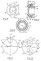
- the clutch bearing represented in FIGS. 1 to 4 essentially comprises a bearing designated by 1 as a whole, with pressed sheet metal rings and angular contact balls, and a support sleeve designated by 2 as a whole, on which one rings 3 of the bearing is mounted with a certain radial freedom at 4 and held axially by means of elastic clips 5a, 5b, the other ring 6 of the bearing being free to rotate and having a front surface 7 intended to cooperate with a clutch actuator, such as a conventional diaphragm shown in phantom in 8.
- a clutch actuator such as a conventional diaphragm shown in phantom in 8.
- the support sleeve 2 is intended to be slidably mounted on a guide tube shown in 9 in phantom in Figure 4, and to undergo axial movements on the latter for the purpose of declutching and clutching, controlled by means of a fork, the fingers of which are represented by a dashed line in FIG. 1.
- the sleeve 2 here in molded synthetic material, has a radial flange 11, the front face of which serves as an axial bearing surface sliding to a flange 12 forming part of the ring 3.
- the flange 11 of the sleeve has at its periphery two opposite tabs 13 directed towards the rear and on which are engaged two metal staples 14, 15 each clipped onto a retaining lug 16 and constituting the surfaces of cooperation of the stop with the fork fingers 10.
- the collar 11 of the sleeve has at its periphery two notched radial bosses 17, in the notches 18 of which. are mounted the clips 5a, 5b in the form of pliers with two branches which serve to hold, by their front branch 19, the flange 12 in axial bearing sliding on the flange 11 of the sleeve and the rear branch 20 of which is clipped onto a lug retainer 21 formed on the rear face of the flange 11.
- these two clips are such that the pinching force or axial retention exerted by one of them on the flanges 11, 12 (and which could be used alone as has been said) is significantly greater than that exercised by the other, in order to allow effective self-centering in all cases as will be explained below.
- FIG. 5 illustrates an alternative embodiment according to which the radial freedom of the ring 3 of the bearing instead of being limited internally by its cooperation with the hub of the sleeve 2a is provided at its periphery at 22, and limited by a circumferential front projection 23 of the flange 24 which surrounds the sleeve thus modified.
- FIGS 6 to 8 illustrate another alternative embodiment according to which the support sleeve 2b of the bearing 1 is modified in that its flange 25 is a simple circular flange, while two clips 5c, 5d pinching the flange 12 of the tank 3 of the bearing and the flange 25 themselves form by their rear branch bent at right angles to the surfaces of cooperation of the stop with the fork fingers 10, the axial branch of the bracket being angularly wedged in a corresponding notch 26 of a radial boss 27 presented by the rear hub of the sleeve for each clip.
- Figures 9 and 10 illustrate with reference to the embodiment of Figures 1 to 4 two cases of obtaining self-centering with a stop according to the invention.
- a force F via is therefore exerted on the rotating ring 6 of the bearing 1.
- the ring 3 will for example be moved radially on the support sleeve 2, following a path passing its axis of II in 111, that is to say at the limit of its radial freedom represented in the drawing by the circle C1, inside which the axis of the bearing 1 can move around the axis II.
- the more general case corresponding to a mounting offset E ' such that the circle C2 for capturing the axis of the bearing is located inside the circle C1 representative of the radial freedom of the axis of the bearing 1.
- the rotation of the diaphragm of the clutch generates on the ring 6 a force F reflected on the ring 3 which will move initially and radially along a trajectory passing for example its axis of Il II'1, that is to say at the limit of its radial freedom corresponding to the circle C1.
- this trajectory of intersection of the collection circle C2 may even be direct when the latter is notably located in the vicinity of the axis Z, Z '.
Landscapes
- Engineering & Computer Science (AREA)
- General Engineering & Computer Science (AREA)
- Mechanical Engineering (AREA)
- Mechanical Operated Clutches (AREA)
Claims (3)
Applications Claiming Priority (2)
| Application Number | Priority Date | Filing Date | Title |
|---|---|---|---|
| FR7929788A FR2470898A1 (fr) | 1979-12-04 | 1979-12-04 | Butee d'embrayage a roulement et a autocentrage |
| FR7929788 | 1979-12-04 |
Publications (2)
| Publication Number | Publication Date |
|---|---|
| EP0030165A1 EP0030165A1 (de) | 1981-06-10 |
| EP0030165B1 true EP0030165B1 (de) | 1983-04-13 |
Family
ID=9232380
Family Applications (1)
| Application Number | Title | Priority Date | Filing Date |
|---|---|---|---|
| EP80401346A Expired EP0030165B1 (de) | 1979-12-04 | 1980-09-19 | Selbstzentrierendes Kupplungsausrücklager |
Country Status (6)
| Country | Link |
|---|---|
| US (1) | US4357058A (de) |
| EP (1) | EP0030165B1 (de) |
| AR (1) | AR223564A1 (de) |
| DE (1) | DE3062758D1 (de) |
| ES (1) | ES8201700A1 (de) |
| FR (1) | FR2470898A1 (de) |
Families Citing this family (29)
| Publication number | Priority date | Publication date | Assignee | Title |
|---|---|---|---|---|
| DE3116168A1 (de) * | 1981-04-23 | 1982-12-09 | Skf Kugellagerfabriken Gmbh, 8720 Schweinfurt | Waelzlager-ausruecker, insbesondere fuer kraftfahrzeugkupplungen |
| FR2510689A1 (fr) * | 1981-07-30 | 1983-02-04 | Valeo | Butee de debrayage, notamment pour vehicule automobile |
| FR2513337A1 (fr) * | 1981-09-21 | 1983-03-25 | Fraymon Sa | Butee de debrayage, notamment pour vehicule automobile |
| DE8137226U1 (de) * | 1981-12-21 | 1982-05-06 | Skf Kugellagerfabriken Gmbh, 8720 Schweinfurt | Schiebehuelse fuer kupplungsausruecker |
| FR2531509B1 (fr) * | 1982-08-03 | 1987-10-09 | Valeo | Butee de debrayage autocentreuse a autocentrage maintenu, notamment pour vehicule automobile |
| DE8315708U1 (de) * | 1983-05-28 | 1983-10-06 | Skf Kugellagerfabriken Gmbh, 8720 Schweinfurt | Kupplungsausruecker |
| JPS6164528U (de) * | 1984-10-04 | 1986-05-01 | ||
| FR2577291B1 (fr) * | 1985-02-08 | 1989-10-13 | Valeo | Butee d'embrayage autocentreuse, notamment pour vehicule automobile, a assemblage compact simplifie |
| FR2586770B1 (fr) * | 1985-09-03 | 1990-07-27 | Valeo | Butee de debrayage a plaque d'appui et agrafes distinctes de celle-ci, notamment pour vehicule automobile. |
| FR2579704B1 (fr) * | 1985-04-01 | 1990-06-22 | Valeo | Butee de debrayage a plaque d'appui en u et agrafes d'un seul tenant avec celle-ci, notamment pour vehicule automobile |
| DE3660509D1 (en) * | 1985-04-01 | 1988-09-15 | Valeo | Clutch release mechanism for a motor vehicle |
| FR2584788B1 (fr) * | 1985-07-15 | 1990-03-30 | Valeo | Butee de debrayage a autocentrage maintenu, avec une rondelle de serrage a elasticite radiale |
| FR2609126B1 (fr) * | 1986-12-29 | 1989-10-27 | Valeo | Butee de debrayage, notamment pour vehicule automobile |
| US4815867A (en) * | 1987-09-23 | 1989-03-28 | Federal-Mogul Corporation | Side assembled clip for self-aligning bearing |
| FR2624229B1 (fr) * | 1987-12-08 | 1991-10-04 | Roulements Soc Nouvelle | Butee de debrayage actionnee par traction |
| FR2624228B1 (fr) * | 1987-12-08 | 1990-04-20 | Roulements Soc Nouvelle | Butee de debrayage actionnee par traction |
| FR2645929B1 (fr) * | 1989-04-18 | 1991-06-07 | Roulements Soc Nouvelle | Dispositif de serrage d'un roulement de butee sur un support coulissant |
| IT1248848B (it) * | 1990-06-14 | 1995-01-30 | Automotive Prod Italia | Gruppo cuscinetto di distacco di frizione |
| FR2663702B1 (fr) * | 1990-06-21 | 1995-05-12 | Skf France | Butee d'embrayage comportant des moyens de solidarisation avec l'organe de manóoeuvre. |
| GB2290362B (en) * | 1994-06-14 | 1998-04-08 | Nsk Ltd | Clutch release apparatus |
| GB2307286B (en) * | 1995-11-15 | 1999-12-01 | Nsk Ltd | Clutch release bearing apparatus |
| FR2755487B1 (fr) * | 1996-11-07 | 1998-12-18 | Skf France | Butee d'embrayage autocentreuse et procede de montage |
| FR2803348B1 (fr) * | 1999-12-30 | 2002-05-17 | Valeo | Butee de debrayage |
| ITRM20010759A1 (it) * | 2000-12-22 | 2003-06-23 | Valeo | Cuscinetto di spinta per innesto, in particolare di autoveicolo e procedimento per il suo assemblaggio. |
| FR2818715B1 (fr) * | 2000-12-22 | 2003-02-07 | Valeo | Butee pour embrayage, notamment de vehicule automobile |
| EP1705374A1 (de) * | 2005-03-04 | 2006-09-27 | Tecumseh do Brasil Ltda. | Zentriervorrichtung für ein Axialdrucklager zur Verhinderung von Reibung in einem hermetischen Kühlmittelverdichter |
| WO2007061103A1 (en) * | 2005-11-22 | 2007-05-31 | Matsushita Electric Industrial Co., Ltd. | Hermetic compressor |
| ATE393885T1 (de) * | 2006-03-03 | 2008-05-15 | Zahnradfabrik Friedrichshafen | Ausrückvorrichtung für eine reibungskupplung eines kraftfahrzeuges mit einer mehrteiligen schiebehülse |
| WO2009054099A1 (en) * | 2007-10-25 | 2009-04-30 | Panasonic Corporation | Compressor |
Family Cites Families (9)
| Publication number | Priority date | Publication date | Assignee | Title |
|---|---|---|---|---|
| FR1589720A (de) * | 1968-09-05 | 1970-04-06 | ||
| GB1338207A (en) * | 1972-06-28 | 1973-11-21 | Ford Motor Co | Clutch release mechanism |
| FR2195297A6 (de) * | 1972-08-02 | 1974-03-01 | Ferodo Sa | |
| DE2363840A1 (de) * | 1973-12-21 | 1975-07-03 | Skf Kugellagerfabriken Gmbh | Kupplungsausruecker |
| DE2457682A1 (de) * | 1974-12-06 | 1976-06-10 | Skf Kugellagerfabriken Gmbh | Kupplungslager |
| FR2304829A1 (fr) * | 1975-03-21 | 1976-10-15 | Ferodo Sa | Butee de debrayage |
| SE414661B (sv) * | 1976-03-31 | 1980-08-11 | Skf Kugellagerfabriken Gmbh | Skjuthylsa |
| FR2391392A1 (fr) * | 1977-05-16 | 1978-12-15 | Skf Cie Applic Mecanique | Butee d'embrayage a auto-centrage comportant des moyens de guidage |
| DE2811195A1 (de) * | 1978-03-15 | 1979-09-20 | Skf Kugellagerfabriken Gmbh | Selbstzentrierendes kupplungsdrucklager |
-
1979
- 1979-12-04 FR FR7929788A patent/FR2470898A1/fr active Granted
-
1980
- 1980-09-19 DE DE8080401346T patent/DE3062758D1/de not_active Expired
- 1980-09-19 EP EP80401346A patent/EP0030165B1/de not_active Expired
- 1980-11-06 ES ES496592A patent/ES8201700A1/es not_active Expired
- 1980-11-26 US US06/210,667 patent/US4357058A/en not_active Expired - Lifetime
- 1980-12-01 AR AR283437A patent/AR223564A1/es active
Also Published As
| Publication number | Publication date |
|---|---|
| FR2470898B1 (de) | 1983-07-22 |
| FR2470898A1 (fr) | 1981-06-12 |
| US4357058A (en) | 1982-11-02 |
| EP0030165A1 (de) | 1981-06-10 |
| DE3062758D1 (en) | 1983-05-19 |
| AR223564A1 (es) | 1981-08-31 |
| ES496592A0 (es) | 1981-12-16 |
| ES8201700A1 (es) | 1981-12-16 |
Similar Documents
| Publication | Publication Date | Title |
|---|---|---|
| EP0030165B1 (de) | Selbstzentrierendes Kupplungsausrücklager | |
| EP0030494B1 (de) | Mechanische Steuerung durch axial verschiebbares Kabel in einem flexiblen Mantel | |
| WO1998026189A1 (fr) | Palier a roulement de colonne de direction pour vehicules automobiles | |
| FR2544429A1 (fr) | Procede pour le montage d'une butee de debrayage, et butee de debrayage correspondante, notamment pour vehicule automobile | |
| FR2540950A1 (fr) | Dispositif de debrayage du type auto-centreur | |
| EP0806581B1 (de) | Kupplungsausrücklager mit einem elastischen Ring | |
| FR2544038A1 (fr) | Ensemble a butee de debrayage | |
| FR2505954A1 (fr) | Butee de debrayage, notamment pour vehicule automobile, procede pour le montage d'une telle butee de debrayage sur une fourchette de commande, et fourchette de commande adaptee a un tel procede | |
| EP0892188B1 (de) | Kupplungsausrücklager mit angesetzter Anschlagsdruckplatte | |
| FR2475170A1 (fr) | Butee d'embrayage a auto-alignement elastique guide | |
| FR2760261A1 (fr) | Dispositif de synchronisation pour boite de vitesses | |
| FR2750182A1 (fr) | Agencement de plaque de pression pour embrayage a friction dans un vehicule automobile | |
| FR3050782A1 (fr) | Ensemble pour un dispositif d'embrayage, notamment pour vehicule automobile | |
| EP3234396B1 (de) | Kupplungsvorrichtung für ein kraftfahrzeug | |
| FR2473142A1 (fr) | Palier de debrayage pour embrayage a friction | |
| EP0699844A1 (de) | Kupplungsbetätigungseinrichtung mit Nachstellvorrichtung | |
| FR2615257A1 (fr) | Butee d'embrayage comportant des moyens d'encliquetage pour la solidarisation axiale avec l'organe de manoeuvre | |
| FR2657174A1 (fr) | Barillet d'objectif avec un montage a vis. | |
| FR2547377A1 (fr) | Dispositif de debrayage | |
| FR2827928A1 (fr) | Mecanisme de debrayage pour un embrayage a friction | |
| WO2009019360A2 (fr) | Mecanisme perfectionne pour embrayage, notamment de vehicule automobile | |
| EP0119907A1 (de) | Axiale Halterung des Segmentes einer Trommelbremse und Trommelbremssegment ausgerüstet mit einer Axialhalterung | |
| FR2733808A1 (fr) | Embrayage a friction a rattrapage d'usure | |
| EP0965004B1 (de) | Kupplungsausrücklager | |
| FR3086022A1 (fr) | Mecanisme d'embrayage a rattrapage d'usure |
Legal Events
| Date | Code | Title | Description |
|---|---|---|---|
| PUAI | Public reference made under article 153(3) epc to a published international application that has entered the european phase |
Free format text: ORIGINAL CODE: 0009012 |
|
| AK | Designated contracting states |
Designated state(s): DE GB IT |
|
| 17P | Request for examination filed |
Effective date: 19810602 |
|
| ITF | It: translation for a ep patent filed | ||
| GRAA | (expected) grant |
Free format text: ORIGINAL CODE: 0009210 |
|
| AK | Designated contracting states |
Designated state(s): DE GB IT |
|
| REF | Corresponds to: |
Ref document number: 3062758 Country of ref document: DE Date of ref document: 19830519 |
|
| ITTA | It: last paid annual fee | ||
| PGFP | Annual fee paid to national office [announced via postgrant information from national office to epo] |
Ref country code: GB Payment date: 19980814 Year of fee payment: 19 |
|
| PGFP | Annual fee paid to national office [announced via postgrant information from national office to epo] |
Ref country code: DE Payment date: 19980821 Year of fee payment: 19 |
|
| PG25 | Lapsed in a contracting state [announced via postgrant information from national office to epo] |
Ref country code: GB Free format text: LAPSE BECAUSE OF NON-PAYMENT OF DUE FEES Effective date: 19990919 |
|
| PG25 | Lapsed in a contracting state [announced via postgrant information from national office to epo] |
Ref country code: DE Free format text: LAPSE BECAUSE OF NON-PAYMENT OF DUE FEES Effective date: 19990930 |
|
| GBPC | Gb: european patent ceased through non-payment of renewal fee |
Effective date: 19990919 |
|
| PLBE | No opposition filed within time limit |
Free format text: ORIGINAL CODE: 0009261 |
|
| STAA | Information on the status of an ep patent application or granted ep patent |
Free format text: STATUS: NO OPPOSITION FILED WITHIN TIME LIMIT |