EP0030211A2 - Mobilier de couchage - Google Patents
Mobilier de couchage Download PDFInfo
- Publication number
- EP0030211A2 EP0030211A2 EP80810358A EP80810358A EP0030211A2 EP 0030211 A2 EP0030211 A2 EP 0030211A2 EP 80810358 A EP80810358 A EP 80810358A EP 80810358 A EP80810358 A EP 80810358A EP 0030211 A2 EP0030211 A2 EP 0030211A2
- Authority
- EP
- European Patent Office
- Prior art keywords
- back part
- foot part
- intermediate member
- reclining furniture
- foot
- Prior art date
- Legal status (The legal status is an assumption and is not a legal conclusion. Google has not performed a legal analysis and makes no representation as to the accuracy of the status listed.)
- Withdrawn
Links
Images


Classifications
-
- A—HUMAN NECESSITIES
- A47—FURNITURE; DOMESTIC ARTICLES OR APPLIANCES; COFFEE MILLS; SPICE MILLS; SUCTION CLEANERS IN GENERAL
- A47C—CHAIRS; SOFAS; BEDS
- A47C17/00—Sofas; Couches; Beds
- A47C17/04—Seating furniture, e.g. sofas, couches, settees, or the like, with movable parts changeable to beds; Chair beds
-
- A—HUMAN NECESSITIES
- A47—FURNITURE; DOMESTIC ARTICLES OR APPLIANCES; COFFEE MILLS; SPICE MILLS; SUCTION CLEANERS IN GENERAL
- A47C—CHAIRS; SOFAS; BEDS
- A47C20/00—Head-, foot- or like rests for beds, sofas or the like
- A47C20/04—Head-, foot- or like rests for beds, sofas or the like with adjustable inclination
- A47C20/041—Head-, foot- or like rests for beds, sofas or the like with adjustable inclination by electric motors
-
- A—HUMAN NECESSITIES
- A47—FURNITURE; DOMESTIC ARTICLES OR APPLIANCES; COFFEE MILLS; SPICE MILLS; SUCTION CLEANERS IN GENERAL
- A47C—CHAIRS; SOFAS; BEDS
- A47C20/00—Head-, foot- or like rests for beds, sofas or the like
- A47C20/08—Head-, foot- or like rests for beds, sofas or the like with means for adjusting two or more rests simultaneously
-
- A—HUMAN NECESSITIES
- A61—MEDICAL OR VETERINARY SCIENCE; HYGIENE
- A61G—TRANSPORT, PERSONAL CONVEYANCES, OR ACCOMMODATION SPECIALLY ADAPTED FOR PATIENTS OR DISABLED PERSONS; OPERATING TABLES OR CHAIRS; CHAIRS FOR DENTISTRY; FUNERAL DEVICES
- A61G2203/00—General characteristics of devices
- A61G2203/70—General characteristics of devices with special adaptations, e.g. for safety or comfort
- A61G2203/74—General characteristics of devices with special adaptations, e.g. for safety or comfort for anti-shear when adjusting furniture
-
- A—HUMAN NECESSITIES
- A61—MEDICAL OR VETERINARY SCIENCE; HYGIENE
- A61G—TRANSPORT, PERSONAL CONVEYANCES, OR ACCOMMODATION SPECIALLY ADAPTED FOR PATIENTS OR DISABLED PERSONS; OPERATING TABLES OR CHAIRS; CHAIRS FOR DENTISTRY; FUNERAL DEVICES
- A61G7/00—Beds specially adapted for nursing; Devices for lifting patients or disabled persons
- A61G7/002—Beds specially adapted for nursing; Devices for lifting patients or disabled persons having adjustable mattress frame
- A61G7/015—Beds specially adapted for nursing; Devices for lifting patients or disabled persons having adjustable mattress frame divided into different adjustable sections, e.g. for Gatch position
Definitions
- the invention relates to a piece of reclining furniture with a rigid frame and a bottom mattress which is movably mounted in the same, which has a back part which can be pivoted about a horizontal axis and a foot part which is articulated thereto, which can also be pivoted about a horizontal axis and for length compensation in the direction of the longitudinal axis of the reclining furniture is slidably mounted in the frame.
- the back part extends over the entire length of the back and is pivotably articulated at the lower end.
- the back part 1 with its articulation 2a arranged on both sides of the lower mattress is connected to a fixed middle part 3 which is rigidly fastened to the frame 4 of the reclining furniture.
- the foot part 6 is arranged on the middle part 3 via a further joint 2b, which in turn can be made in two parts and is guided laterally in the frame 4 via pins 7.
- Lifting and Lowering of the moving parts 1 and 6 is usually done via one or two motors, not shown.
- the back part 1 can thus be brought into any inclined position by actuating a motor until the desired seating position is reached.
- this sitting position is not a fixed position that you take forever and then keep. Because on the one hand the seated person will always have the tendency to slide away on the middle part 3 in the direction of the arrow P; on the other hand, the rigid retention of a position once taken is uncomfortable in the long run, so that the seated person involuntarily looks for a change in position, albeit a minor one.
- Another disadvantage of this known construction is that be on the bottom mattress sensitive top mattress in the area of the joint 2a is kinked sharply in the sitting position and slips on the bottom mattress every time the seated person changes position. It is also very difficult for the seated person to find and maintain the correct anatomically correct support position.
- foot part is to be understood to include that section of the lower mattress that essentially serves to support the legs. This foot section can be in one or more parts and, together with the back section, is used to hold the top mattress.
- Fig. 2 shows schematically a rigid frame 8, which has two longitudinal frames in the usual way, which are connected to one another via cross struts.
- a pivot bearing 9 is attached to each longitudinal frame of the frame 8; by means of pivot pins 10, the back part 11 of a lower mattress is suspended in the bearings 9, so that the same can be pivoted about the common axis of the pivot pins 10/10.
- the swivel axis is 10 /. 10 of the back part not at the inner end of the back part 11, but between the two end sections thereof, i.e. at a distance lla from the inner back edge.
- the section 11a of the back part lying within the swivel axis 10/10 passes below the normal lying plane (cf. also FIGS. 3 and 4).
- the foot part of the lower mattress designated by 12 in FIG. 2 consists of two sections 13 and 14 which can be pivoted relative to one another by a joint 15.
- Pins 16, 17 and 18 protruding from the foot part on both sides are slidably guided in guide rails 19, 20 and 21, which are fastened to the inner surfaces of the longitudinal frame members, so that section 13 corresponds accordingly the inclination of the guide rail 20 assumes an inclined position during its movement.
- the section 14 is rotated about the axis of the pair of pins 18.
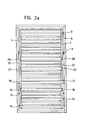
- each individual intermediate member 22 could extend over the entire width of the lower mattress, but in the selected embodiment is only arranged as an extension of the two longitudinal frames L of the back part 11 (FIG. 2a).
- the two intermediate members 22 are connected to one another by at least one crossbar Q.
- joints 27 and 28 are preferably designed as elastic joints.
- the two intermediate links 22 of each sub-mattress are thus connected freely to the adjacent sections 11 and 14 via the joints 27 and 28.
- the length L (FIG.
- each intermediate member 22 is preferably between 1/5 and 1/10 of the total length of the back part 11 and is approximately 1/6 of the same in a special embodiment.
- a motor 24 is articulated via a bearing 23, the drive rod 25 of which engages via a bearing 26 on the inner end section of the back part 11,
- the motor 24 is actuated and the back part 11 is thus pivoted in the direction of the arrow P1.
- the freely suspended intermediate member 22 has the possibility of adopting different positions under different loads and thus adapting to different sitting positions and anatomical differences in the body structure (e.g. different thigh length).
- the intermediate member 22 assumes, as it were, a middle position in which the two angles a and ⁇ which it forms with the adjacent sections are practically the same.
- the pontic will assume this position when the load Q exerted by the user on it practically acts in the center, i.e. the main load of the seated person rests on his buttocks on a crossbar which connects the centers of the two intermediate members 22 to one another.
- This "resilience" of the intermediate member 22 is not only dependent on the load Q and its point of application, because the intermediate member 22 is connected via the joints 27/28 to the adjacent lower mattress sections 11/14 to form a movable system.
- the tensile force on the back part 11 acts on each intermediate member 22, as does the pulling effect exerted by the foot part 6, which depends on the weight of the resting legs and can be influenced by the seated person by stretching or particularly stressing the leg area.
- the seated person had the need to slide further from the inclined position according to FIG. 3 with the buttocks in the direction of arrow P4 in order to achieve a steeper angle of the back part and a more favorable load situation in the area of the intermediate member 22, so would finally have resulted in the seating position according to FIG. 5.
- the buttocks are shifted in the direction of P4, on the one hand, according to the wishes of the seated person; on the other hand, the back part 11, the intermediate member 22 and the foot part 6 have adapted to the new load situation in such a way that the most comfortable sitting position with complete support of the spine is again achieved.
- the intermediate member 22 thus allows the respective seating position to be automatically adjusted to any load conditions, which the seated person can influence not only by shifting the center of gravity but also by stretching the legs, particularly stressing the foot part or back part etc.
- FIGS. 6 to 8 shows two metallic fastening elements, in the present case two plate-shaped steel legs 29 and 30, one of which - 30 - has a fork-shaped extension 31 on its upper part, with which it attaches the upper, angled part 32 of the other steel leg 29 engages.
- Both steel legs are articulated to one another at the overlap point by means of a bolt 33 connected and can thus be pivoted about the axis of the bolt 33 in the direction of the double arrow P5.
- Fastening bolts 35 are arranged on the flanks 34 of the steel legs 29, 30 ' , which allow the steel legs of the joint to be firmly anchored at the ends of two adjacent longitudinal frame sections.
- the fastening bolts 35 are thus fastened in the mutually facing surfaces of the back part 11 and the intermediate member 22 on the one hand and the intermediate member 22 and the foot section 14 on the other hand.
- the bolts are cylindrical and have transverse bores 36 for locking by means of pins, but it would of course also be possible to choose a different type of fastening which is readily accessible to the person skilled in the art.
- the corrugated separating surface of the two legs 38 and 39 opens into an arcuate, continuous slot 41, above which a non-continuous, also arcuate groove 42 is provided on both sides. Between the slot 41 and the groove 42 there is therefore a web 43, which acts as an elastic return element when the joint is spreading, but generates a certain outward counterpressure when the joint is compressed.
- the intermediate member 22 By installing the intermediate member 22, on the one hand, the undesirable, strong kinking of the top mattress in the sitting position is avoided and, on the other hand, the unpleasant slipping of the top mattress is reduced to a minimum. Since the intermediate link 22 is suspended between the back part and the foot part, the anatomically correct support position for the seat and back of the seated person results depending on the size and point of application of the load.
Landscapes
- Health & Medical Sciences (AREA)
- General Health & Medical Sciences (AREA)
- Nursing (AREA)
- Chairs For Special Purposes, Such As Reclining Chairs (AREA)
- Special Chairs (AREA)
- Invalid Beds And Related Equipment (AREA)
Applications Claiming Priority (3)
| Application Number | Priority Date | Filing Date | Title |
|---|---|---|---|
| CH1059179A CH642832A5 (en) | 1979-11-28 | 1979-11-28 | Bed |
| CH10590/79 | 1979-11-28 | ||
| CH1059079A CH643722A5 (de) | 1979-11-28 | 1979-11-28 | Liegemoebel. |
Publications (2)
| Publication Number | Publication Date |
|---|---|
| EP0030211A2 true EP0030211A2 (fr) | 1981-06-10 |
| EP0030211A3 EP0030211A3 (fr) | 1981-11-04 |
Family
ID=25706955
Family Applications (1)
| Application Number | Title | Priority Date | Filing Date |
|---|---|---|---|
| EP80810358A Withdrawn EP0030211A3 (fr) | 1979-11-28 | 1980-11-20 | Mobilier de couchage |
Country Status (7)
| Country | Link |
|---|---|
| US (1) | US4403357A (fr) |
| EP (1) | EP0030211A3 (fr) |
| AT (1) | AT385888B (fr) |
| CA (1) | CA1155605A (fr) |
| CH (2) | CH642832A5 (fr) |
| DE (1) | DE8030521U1 (fr) |
| ES (1) | ES253965Y (fr) |
Cited By (2)
| Publication number | Priority date | Publication date | Assignee | Title |
|---|---|---|---|---|
| WO1995017839A3 (fr) * | 1993-12-23 | 1995-07-27 | Anton Mamic | Ameliorations d'un cadre de lit |
| CN110719766A (zh) * | 2017-07-14 | 2020-01-21 | 马尔韦斯蒂奥股份公司 | 保健床 |
Families Citing this family (27)
| Publication number | Priority date | Publication date | Assignee | Title |
|---|---|---|---|---|
| ATE40275T1 (de) * | 1983-09-07 | 1989-02-15 | Marius Boonants | Gegliederte untermatratze. |
| US4685160A (en) * | 1985-04-25 | 1987-08-11 | Mckesson Corporation | Portable bed assembly |
| AT384542B (de) * | 1986-02-28 | 1987-11-25 | Riedl Georg | Bett |
| US4851070A (en) * | 1987-11-25 | 1989-07-25 | Tachi-S Company, Ltd. | Method of forming an automotive seat having a cover inserted in a lateral groove |
| DE3901730C2 (de) * | 1989-01-21 | 1997-08-14 | Kettler Metallwaren Heinz | Sesselliege |
| US4996731A (en) * | 1989-04-19 | 1991-03-05 | Kruyt Robert A | Adjustable bed |
| FR2679428B1 (fr) * | 1991-07-26 | 1995-12-08 | Francois Martin | Element de mobilier, comme une tetiere, a inclinaison variable et lit equipe d'une telle tetiere. |
| US5230113A (en) * | 1992-04-14 | 1993-07-27 | Good Turn, Inc. | Multiple position adjustable day night patient bed chair |
| NO305732B1 (no) * | 1996-04-11 | 1999-07-19 | Kjartan Alvestad | Reguleringsanordning for ligge- eller sittem°bel |
| EP1011389B1 (fr) * | 1997-02-28 | 2003-02-05 | Kjartan Alvestad | Dispositif de reglage destine a des lits et autre mobilier pouvant s'incliner ou du type siege |
| GB9808675D0 (en) * | 1998-04-24 | 1998-06-24 | Comfort & Care Limited | Smart bed |
| SE0101017D0 (sv) * | 2001-03-23 | 2001-03-23 | Proton Ind Ab | Säng |
| US6684420B2 (en) * | 2001-04-27 | 2004-02-03 | Hill-Rom Services, Inc. | Crib apparatus |
| US20040216235A1 (en) * | 2001-11-22 | 2004-11-04 | Rees John Christopher | Bed |
| DE20304868U1 (de) | 2002-06-27 | 2003-11-06 | Cimosys Ag, Goldingen | Verstellvorrichtung für Betten, Matratzen, Sessel u.dgl. |
| DE20217759U1 (de) * | 2002-07-10 | 2004-04-01 | Cimosys Ag | Verstellvorrichtung für Betten, Matratzen, Sessel u.dgl. |
| US7124456B2 (en) * | 2004-08-11 | 2006-10-24 | Stryker Corporation | Articulated support surface for a stretcher or gurney |
| US7637464B2 (en) | 2006-01-19 | 2009-12-29 | Hill-Rom Services, Inc. | Patient support with mobile IV stand transport handle |
| DE102007009596B4 (de) * | 2007-02-26 | 2013-11-21 | Hanning Elektro-Werke Gmbh & Co. Kg | Verstellvorrichtung für Möbel und Verschwenkverfahren |
| US9149403B2 (en) * | 2010-09-24 | 2015-10-06 | Hill-Rom Services, Inc. | Bed frame, mattress and bed with enhanced chair egress capability |
| WO2013192411A2 (fr) * | 2012-06-21 | 2013-12-27 | Meyer Eric R | Systèmes de soutien pour patient et leurs procédés d'utilisation |
| GB2520046B (en) * | 2013-11-07 | 2016-01-13 | Univ Cape Town | Anatomical support facilitating medical imaging of the hip, leg and knee |
| WO2017109894A1 (fr) * | 2015-12-24 | 2017-06-29 | 富士通株式会社 | Lit |
| USD811112S1 (en) * | 2016-01-22 | 2018-02-27 | Ascion, Llc | Adjustable bed foundation |
| CN106724331B (zh) * | 2016-12-30 | 2019-01-15 | 浙江世道电器有限公司 | 背部悬空下沉式电动护理床架 |
| WO2018175376A1 (fr) * | 2017-03-24 | 2018-09-27 | Bedgear, Llc | Lit à gravité nulle |
| TWI803397B (zh) * | 2022-07-21 | 2023-05-21 | 施權航 | 電動床 |
Family Cites Families (13)
| Publication number | Priority date | Publication date | Assignee | Title |
|---|---|---|---|---|
| US525959A (en) * | 1894-09-11 | Adjustable bedstead | ||
| GB409463A (en) * | 1933-01-12 | 1934-05-03 | Ernest Vaughan | Improvements relating to mattresses |
| US2337395A (en) * | 1941-03-03 | 1943-12-21 | Jr Warren Allston Leland | Invalid bed |
| US2500742A (en) * | 1945-07-30 | 1950-03-14 | Marvel Beem | Invalid's bed |
| GB609442A (en) * | 1946-03-14 | 1948-09-30 | Leslie Haywood Hounsfield | Improvements in and relating to collapsible bedsteads |
| FR1295987A (fr) * | 1961-04-29 | 1962-06-15 | Lit, notamment de relaxation, à sommier articulé | |
| US3253285A (en) * | 1965-01-04 | 1966-05-31 | Seng Co | Bed lounge mechanism |
| US3312985A (en) * | 1966-07-05 | 1967-04-11 | Invalift Corp | Invalid bed with lifting mechanism |
| US3540777A (en) * | 1967-12-02 | 1970-11-17 | Mario Revelli De Beaumont | Chair for automotive vehicles with a displaceable back |
| US3703742A (en) * | 1970-04-13 | 1972-11-28 | New Lite Ind Co Ltd | Plastic hinge |
| DE2253360A1 (de) * | 1972-10-31 | 1974-05-09 | Happich Gmbh Gebr | Einstueckiges kunststoff-scharnier |
| ZA746085B (en) * | 1974-05-11 | 1975-11-26 | Lusch Kg Ferd | Bed or settee with a multi-part mattress frame |
| US4057873A (en) * | 1976-03-25 | 1977-11-15 | Rudolph Bursani | Door hinge coupling device |
-
1979
- 1979-11-28 CH CH1059179A patent/CH642832A5/de not_active IP Right Cessation
- 1979-11-28 CH CH1059079A patent/CH643722A5/de not_active IP Right Cessation
-
1980
- 1980-01-18 AT AT0026180A patent/AT385888B/de not_active IP Right Cessation
- 1980-10-29 ES ES1980253965U patent/ES253965Y/es not_active Expired
- 1980-11-07 CA CA000364211A patent/CA1155605A/fr not_active Expired
- 1980-11-14 DE DE19808030521U patent/DE8030521U1/de not_active Expired
- 1980-11-18 US US06/207,843 patent/US4403357A/en not_active Expired - Lifetime
- 1980-11-20 EP EP80810358A patent/EP0030211A3/fr not_active Withdrawn
Cited By (2)
| Publication number | Priority date | Publication date | Assignee | Title |
|---|---|---|---|---|
| WO1995017839A3 (fr) * | 1993-12-23 | 1995-07-27 | Anton Mamic | Ameliorations d'un cadre de lit |
| CN110719766A (zh) * | 2017-07-14 | 2020-01-21 | 马尔韦斯蒂奥股份公司 | 保健床 |
Also Published As
| Publication number | Publication date |
|---|---|
| DE8030521U1 (de) | 1981-04-23 |
| CH642832A5 (en) | 1984-05-15 |
| ATA26180A (de) | 1987-11-15 |
| CA1155605A (fr) | 1983-10-25 |
| ES253965U (es) | 1981-02-16 |
| EP0030211A3 (fr) | 1981-11-04 |
| AT385888B (de) | 1988-05-25 |
| ES253965Y (es) | 1981-08-16 |
| CH643722A5 (de) | 1984-06-29 |
| US4403357A (en) | 1983-09-13 |
Similar Documents
| Publication | Publication Date | Title |
|---|---|---|
| EP0030211A2 (fr) | Mobilier de couchage | |
| DE69122268T2 (de) | Stuhl für körperlich behinderte personen | |
| DE60208889T2 (de) | Fussgelenksorthose | |
| DE69415239T2 (de) | Untermatratze | |
| EP0151221B1 (fr) | Ski pour handicapé | |
| EP1721801B1 (fr) | Dispositif pour protéger les usagers sur le siège d'un télésiège | |
| DE2724586A1 (de) | Orthopaedische schiene zur stuetzung des kniegelenkes | |
| DE69517674T2 (de) | Verstellbare Sitzanordnung | |
| DE69024819T2 (de) | Gelenk | |
| DE1147711B (de) | Abduktionsschiene | |
| DE8901646U1 (de) | Vorrichtung zum Stützen des Rückens | |
| EP0539644A1 (fr) | Sommier à lattes | |
| DE7701585U1 (de) | In ein bett verwandelbares sitzmoebel | |
| DE10307738B4 (de) | Neigungsverstellvorrichtung für mindestens einen Teil einer Liege- oder Sitzfläche | |
| EP0050107A2 (fr) | Meuble d'assise | |
| DE20000617U1 (de) | Möbel zum Sitzen und/oder Liegen | |
| AT524133B1 (de) | Medizinische Orthese | |
| DE1654317B1 (de) | federanordnung für sitzrahmen von m¦beln | |
| DE2028612A1 (de) | Aufhangung für einen Fahrzeugsitz | |
| DE19540008C1 (de) | Kranken- oder Pflegebett mit einer mehrteiligen Liegefläche | |
| EP3613396A1 (fr) | Dispositif de transport des malades | |
| DE4040097C2 (fr) | ||
| DE3941645C2 (fr) | ||
| DE19942444C1 (de) | Sitzeinrichtung zum hängenden Befördern von Personen | |
| DE3009073A1 (de) | Verstellbares liegemoebel |
Legal Events
| Date | Code | Title | Description |
|---|---|---|---|
| PUAI | Public reference made under article 153(3) epc to a published international application that has entered the european phase |
Free format text: ORIGINAL CODE: 0009012 |
|
| AK | Designated contracting states |
Designated state(s): BE DE FR GB IT LU NL SE |
|
| ITCL | It: translation for ep claims filed |
Representative=s name: BARZANO' E ZANARDO MILANO S.P.A. |
|
| PUAL | Search report despatched |
Free format text: ORIGINAL CODE: 0009013 |
|
| AK | Designated contracting states |
Designated state(s): BE DE FR GB IT LU NL SE |
|
| 17P | Request for examination filed |
Effective date: 19811126 |
|
| STAA | Information on the status of an ep patent application or granted ep patent |
Free format text: STATUS: THE APPLICATION HAS BEEN WITHDRAWN |
|
| 18W | Application withdrawn |
Withdrawal date: 19840407 |
|
| RIN1 | Information on inventor provided before grant (corrected) |
Inventor name: DEGEN, HUGO |