EP0030306A2 - Vorderradaufhängungssystem für Motorrad - Google Patents
Vorderradaufhängungssystem für Motorrad Download PDFInfo
- Publication number
- EP0030306A2 EP0030306A2 EP80107259A EP80107259A EP0030306A2 EP 0030306 A2 EP0030306 A2 EP 0030306A2 EP 80107259 A EP80107259 A EP 80107259A EP 80107259 A EP80107259 A EP 80107259A EP 0030306 A2 EP0030306 A2 EP 0030306A2
- Authority
- EP
- European Patent Office
- Prior art keywords
- wheel
- carrying element
- swinging arms
- axle
- shock absorber
- Prior art date
- Legal status (The legal status is an assumption and is not a legal conclusion. Google has not performed a legal analysis and makes no representation as to the accuracy of the status listed.)
- Granted
Links
Images
Classifications
-
- B—PERFORMING OPERATIONS; TRANSPORTING
- B62—LAND VEHICLES FOR TRAVELLING OTHERWISE THAN ON RAILS
- B62K—CYCLES; CYCLE FRAMES; CYCLE STEERING DEVICES; RIDER-OPERATED TERMINAL CONTROLS SPECIALLY ADAPTED FOR CYCLES; CYCLE AXLE SUSPENSIONS; CYCLE SIDECARS, FORECARS, OR THE LIKE
- B62K25/00—Axle suspensions
- B62K25/04—Axle suspensions for mounting axles resiliently on cycle frame or fork
- B62K25/12—Axle suspensions for mounting axles resiliently on cycle frame or fork with rocking arm pivoted on each fork leg
- B62K25/22—Axle suspensions for mounting axles resiliently on cycle frame or fork with rocking arm pivoted on each fork leg with more than one arm on each fork leg
- B62K25/24—Axle suspensions for mounting axles resiliently on cycle frame or fork with rocking arm pivoted on each fork leg with more than one arm on each fork leg for front wheel
-
- Y—GENERAL TAGGING OF NEW TECHNOLOGICAL DEVELOPMENTS; GENERAL TAGGING OF CROSS-SECTIONAL TECHNOLOGIES SPANNING OVER SEVERAL SECTIONS OF THE IPC; TECHNICAL SUBJECTS COVERED BY FORMER USPC CROSS-REFERENCE ART COLLECTIONS [XRACs] AND DIGESTS
- Y10—TECHNICAL SUBJECTS COVERED BY FORMER USPC
- Y10T—TECHNICAL SUBJECTS COVERED BY FORMER US CLASSIFICATION
- Y10T74/00—Machine element or mechanism
- Y10T74/20—Control lever and linkage systems
- Y10T74/20576—Elements
- Y10T74/20732—Handles
- Y10T74/2078—Handle bars
- Y10T74/20786—Spring biased or supported
Definitions
- the present invention relates to a suspension system for a motorvehicle wheel, particularly for a motorcycle wheel, comprising on at least one, and preferably on both of the sides of the wheel, two substantially upright swinging arms disposed in a plane substantially parallel to the plane of the wheel, and which are pivoted at their upper ends to a supporting structure of the vehicle and at their lower ends to a wheel-carrying element, so that the supporting structure, the two swinging arms and the wheel-carrying element form an articulated quadrilateral, the wheel-carrying element having a prolongation which is parallel to the plane of the wheel and which extends forward or backward beyond the two pivotal connections between the two swinging arms and the wheel-carrying element, with the wheel being mounted on the said prolongation and with at least one resilient means and at least one shock absorber acting on the said articulated quadrilateral to oppose relative movement between the supporting structure and the wheel-carrying element due to a load applied to the motorvehicle.
- the shock absorber works in fact within the high speed range, so that it exerts a great cushioning power, and then it works within the low speed range, so that its cushioning power decreases towards the end of its stroke.
- the invention aims to obtain that the shock absorber functions at high speeds, i.e. at the beginning of the wheel axle excursion, with a great ratio between the wheel axle excursion and the shock absorber stroke and at low speeds, i.e.
- the wheel axle which is mounted on the prolongation of the wheel-carrying element is substantially located on the ideal straight line passing through the pivotal connections of the two swinging arms to the wheel-carrying element, or slightly over or under the said straight line, while the shock absorber has its upper end pivoted either directly or indirectly to the supporting structure, or to one of the swinging arms, and its lower end pivoted either directly or indirectly to the wheel-carrying element, in a position located under the said ideal straight line passing through the pivotal connections of the two swinging arms to the wheel-carrying element, within an area substantially included between the median perpendicular to the section between the pivotal connections of the two swinging arms to the wheel-carrying element, and the median perpendicular to the section between the wheel axle and the pivotal connection of the swinging arm,which is nearer to the wheel axle, to. the wheel-carrying element.
- the lower end of the shock absorber is pivoted either directly or indirectly to the wheelrcarrying element, at a position located in the area lying under the pivotal connection of the swinging arm, which is nearer to the wheel axle, to the said wheel-carrying element.
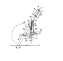
- the front suspension system for motorcycles comprises a steering column 1 which is integral with the motorcycle body 2.
- a steering column 1 which is integral with the motorcycle body 2.
- the steering pin 3 Rotatably mounted inside the steering column 1 there is the steering pin 3 with which two cross members are integral, an upper cross member 4 and a lower cross member 5.
- the cross members 4 and 5 are in turn integral with the two arms 6 of an upper steerable fork.
- the arms 6 are arranged in a spaced apart parallel relation, and extend downward, substantially in the direction of axis 7 of the steering column 1,
- the axle 8 of wheel 9 is mounted in correspondence with the fore open end of a lower fork 10 placed in a position slightly inclined with respect to the horizontal.
- an articulated system comprising two substantially upright swinging arms 11 and 12 arranged in a not-parallel relation, and for example converging in the downward direction, i.e. towards the respective wheel-carrying arm 110 of the lower fork 10.
- the said swinging arms 11, 12 have their upper ends pivoted at 111 and 112 to arm 6 of the upper fork, and their lower ends pivoted at 211 and 212 to the wheel-carrying arm 110 of the lower fork 10, in a zone which is spaced apart, and more particularly retracted from the wheel axle 8.
- the two swinging arms 11, 12 form with the respective arm 6 of the upper fork and with the respective wheel-carrying arm 110 of the lower fork 10 an articulated quadrilateral.
- the axle 8 of wheel 9 is mounted on the forward prolongation of the wheel-carrying arm 110 of the lower fork 10 beyond the pivotal connection 211 between the said wheel-carrying arm 110 and the fore swinging arm 11.
- axle 8 of wheel 9 is located slightly under the ideal straight line 13 passing through the pivotal connections 211, 212 between the two swinging arms 11, 12 and the respective wheel--carrying arm 110 of the lower fork 10.
- the axle 8 of wheel 9 is located also before the axis 7 of the steering column 1.
- the geometry of the aforedescribed articulated system is such that the axle 8 of wheel 9 is moved along an excursion path with a shape corresponding to the requirements of the specific case, and more particularly along an excursion path 14 which is rectilinear or almost rectilinear, and possibly also parallel or almost parellel to the axis 7 of the steering column 1, for example so as to keep the foreun A constant over the entire excursion of the wheel.
- Each articulated system comprises also a shook absorber 15 which is associated to a spring system consisting of one or more springs 16, and which by its upper end is pivoted at 115 to the respective arm 6 of the upper fork, and by its lower end is pivoted at point 215 to the respective wheel--carrying arm 110 of the lower fork 10, or, more precisely, to an arcuate member 210 extending under the wheel-carrying arm 110 and integral therewith.
- a shook absorber 15 which is associated to a spring system consisting of one or more springs 16, and which by its upper end is pivoted at 115 to the respective arm 6 of the upper fork, and by its lower end is pivoted at point 215 to the respective wheel--carrying arm 110 of the lower fork 10, or, more precisely, to an arcuate member 210 extending under the wheel-carrying arm 110 and integral therewith.
- the lower point 215 of pivotal connection of shock absorber 15 is sensibly below the ideal straight line 13 passing through the pivotal connections 211 and 212 between the wheel-carrying arm 110 of the lower fork 10 and the two swinging arms 11, 12. Moreover, the lower point 215 of pivotal connection of shock absorber 15 is located in the area included between the median perpendicular 17 to the section of the said ideal right line 13 between the pivotal connections 211, 212 of the two swinging arms 11, 12 to the wheel-carrying arm 110 of the lower fork 10 and the median perpendicular 18 to the segment of the said straight line 13 between the axle 8 of wheel 9 and the pivotal connection 211 of the fore swinging arm 11 to the wheel-carrying arm 110 of the lower fork 10.
- the lower point g15 of pivotal connection of shock absorber 15 is located in the area lying under the pivotal connection between the wheel-carrying arm 110 of the lower fork 10 and the swinging arm 11 which is nearer to the axle 8 of wheel 9, i.e., the fore swinging arm, in the present case.
- the ratio between the excursion of axle 8 of wheel 9 and the stroke of shock absorber 15 is initially great, but decreases towards the end of the excursion of axle 8 of wheel 9. Therefore, even when the shock absorber 15 is of a usual type, in which the cushioning power is a function of speed, for example during the landing phase of a motorcycle after it has taken a jump, a smaller deceleration is obtained at the beginning, which is due to the initially lpwer cushioning power of the shock absorber, and which however increases towards the end of the shock absorber stroke, as a result of the respective increase of the shock absorber cushioning power.
- a soft contact of wheel 9 with the ground is achieved, while a blunt shock is prevented at the end of the stroke of shock absorber 15.
- the two shock absorbers 15 which are provided on both sides of wheel 9, are each arranged in an inner position, between the wheel 9 and the respective articulated lateral suspension system in which the wheel-carrying arm 110 of the lower fork 10 and the arm 6 of the upper fork are preferably disposed between the respective shock absorber 15 and the two swinging arms 11, 12 which are thus located in a more external position.
- shock absorbers 15 reduces the inertia relative to the axis 7 of the steering column 1, and the eccentric masses relative to the vertical plane of wheel 9.
- the invention is not limited to motorcycles, nor to the front suspensions, but is applicable to any other vehicles, and also to the rear suspensions.
- the articulated suspension system may be specularly arranged with respect to the illustrated system, i.e., the wheel axle will be mounted at the rear end of the lower fork 10, while the two swinging arms 11, 12 will be pivoted to the fore end of said fork 10, and the upper fork provided with arms 6 will be constituted by a part of the vehicle body.
- the invention is not limited to the particular construction of the shown embodiment, but is applicable to any other construction and configuration of the suspension system consisting of the articulated quadrilateral formed by the upper suspension structure (body or steerable fork), the lower wheel-carrying structure and the not-parallel swinging arms pivotally connected between the said two structures.
- the lower wheel-carrying structure may consist of a fork more or less inclined with respect to the horizontal or substantially horizontal, or the whole or in part inclined or horizontal, as shown, but might be also formed by an analogous frame, or generally by two wheel-carrying arms arranged on opposite sides of the wheel, and which are made and connected to each other in any desired manner.
- At least one end of shock absorber 15 might be pivoted even indirectly, i.e., with the interposition of any mechanioal transmission system, such as for example a linkage, to the respective upper and/or lower pivotal connection point 115, 215.
Landscapes
- Engineering & Computer Science (AREA)
- Mechanical Engineering (AREA)
- Axle Suspensions And Sidecars For Cycles (AREA)
- Vehicle Body Suspensions (AREA)
- Arrangement Or Mounting Of Propulsion Units For Vehicles (AREA)
- Fluid-Damping Devices (AREA)
Priority Applications (1)
| Application Number | Priority Date | Filing Date | Title |
|---|---|---|---|
| AT80107259T ATE19032T1 (de) | 1979-12-07 | 1980-11-21 | Vorderradaufhaengungssystem fuer motorrad. |
Applications Claiming Priority (2)
| Application Number | Priority Date | Filing Date | Title |
|---|---|---|---|
| IT12861/79A IT1124375B (it) | 1979-12-07 | 1979-12-07 | Sospensione a quadrilatero articolato con almeno un ammortizzatore per ruote di autoveicoli in particolare di motocilette |
| IT1286179 | 1979-12-07 |
Publications (3)
| Publication Number | Publication Date |
|---|---|
| EP0030306A2 true EP0030306A2 (de) | 1981-06-17 |
| EP0030306A3 EP0030306A3 (en) | 1982-05-19 |
| EP0030306B1 EP0030306B1 (de) | 1986-04-09 |
Family
ID=11143593
Family Applications (1)
| Application Number | Title | Priority Date | Filing Date |
|---|---|---|---|
| EP80107259A Expired EP0030306B1 (de) | 1979-12-07 | 1980-11-21 | Vorderradaufhängungssystem für Motorrad |
Country Status (9)
| Country | Link |
|---|---|
| US (1) | US4410196A (de) |
| EP (1) | EP0030306B1 (de) |
| JP (1) | JPS56131479A (de) |
| AT (1) | ATE19032T1 (de) |
| AU (1) | AU537162B2 (de) |
| CA (1) | CA1138346A (de) |
| DE (1) | DE3071540D1 (de) |
| ES (1) | ES497554A0 (de) |
| IT (1) | IT1124375B (de) |
Cited By (13)
| Publication number | Priority date | Publication date | Assignee | Title |
|---|---|---|---|---|
| FR2511335A1 (fr) * | 1981-08-17 | 1983-02-18 | Honda Motor Co Ltd | Systeme de suspension avant pour motocyclettes |
| US4401316A (en) * | 1980-03-17 | 1983-08-30 | Honda Giken Kogyo Kabushiki Kaisha | Front suspension for motocycle |
| US4406475A (en) * | 1980-03-17 | 1983-09-27 | Honda Giken Kogyo Kabushiki Kaisha | Front wheel suspension system for motorcycles |
| GB2201642A (en) * | 1987-01-12 | 1988-09-07 | Elf France | Front wheel suspension linkage |
| WO2018104906A1 (en) * | 2016-12-07 | 2018-06-14 | Piaggio & C. S.P.A. | Suspension group for motor vehicle, wheel group for motor vehicle, front end of a motor vehicle and motor vehicle thereof |
| USD859125S1 (en) | 2018-02-08 | 2019-09-10 | Trvstper, Inc. | Cycle suspension rebound knob |
| USD860062S1 (en) | 2018-02-08 | 2019-09-17 | Trvstper, Inc. | Cycle suspension assembly |
| USD860061S1 (en) | 2018-02-08 | 2019-09-17 | Trvstper, Inc. | Cycle suspension assembly |
| USD861542S1 (en) | 2018-02-08 | 2019-10-01 | Trvstper, Inc. | Cycle suspension assembly |
| US11820457B2 (en) | 2018-10-16 | 2023-11-21 | Specialized Bicycle Components, Inc. | Cycle suspension with travel indicator |
| US11945539B2 (en) | 2018-09-07 | 2024-04-02 | Specialized Bicycle Components, Inc. | Dual sided suspension assembly for a cycle wheel |
| US12258095B2 (en) | 2019-04-09 | 2025-03-25 | Specialized Bicycle Components, Inc. | Cycle suspension with rotation sensor |
| US12319381B2 (en) | 2018-09-25 | 2025-06-03 | Specialized Bicycle Components, Inc. | Trailing link cycle wheel suspension assembly having gas pistons with unequal gas piston areas |
Families Citing this family (41)
| Publication number | Priority date | Publication date | Assignee | Title |
|---|---|---|---|---|
| US4542910A (en) * | 1982-01-25 | 1985-09-24 | Yamaha Hatsudoki Kabushiki Kaisha | Motorcycle suspension system |
| DE3369291D1 (en) * | 1982-07-26 | 1987-02-26 | Terence Anthony Haynes | A motorcycle front fork assembly |
| US5377557A (en) * | 1993-04-15 | 1995-01-03 | Nastrucci; Gianfranco | Cushioned mount for bicycle handlebars |
| US6036211A (en) * | 1996-04-25 | 2000-03-14 | Nohr; Mark W. | Bicycle front suspension |
| US6152472A (en) * | 1996-09-30 | 2000-11-28 | Engineered Progression Inc. | Stability maintaining and shock absorbing front fork assembly for bicycles |
| US7722072B2 (en) | 2004-09-15 | 2010-05-25 | Yeti Cycling, Llc | Rear suspension system for a bicycle |
| EP2605953B1 (de) | 2010-08-20 | 2021-06-16 | Yeti Cycling LLC | Bindeglied-aufhängungssystem |
| US9821879B2 (en) | 2010-08-20 | 2017-11-21 | Yeti Cycling, Llc | Reciprocating rail movement suspension system |
| US8448970B1 (en) | 2011-06-30 | 2013-05-28 | Douglas L. Vardon | Suspension system for steerable front wheel of vehicle |
| USD666947S1 (en) | 2011-06-30 | 2012-09-11 | Vardon Douglas L | Front suspension assembly for a motorcycle |
| US8783704B2 (en) | 2012-09-13 | 2014-07-22 | Dennis P. Richards | Suspension system |
| US10766563B2 (en) | 2013-01-16 | 2020-09-08 | Yeti Cyclying, Llc | Rail suspension with integral shock and dampening mechanism |
| JP6722916B2 (ja) | 2016-03-31 | 2020-07-15 | 株式会社エクォス・リサーチ | 車両 |
| US12600431B2 (en) | 2017-03-17 | 2026-04-14 | Yeti Cycling, Llc | Vehicle suspension linkage |
| EP3595963A4 (de) | 2017-03-17 | 2021-03-10 | Yeti Cycling, LLC | Fahrzeugaufhängungsgelenk |
| US10926830B2 (en) | 2017-07-07 | 2021-02-23 | Yeti Cycling, Llc | Vehicle suspension linkage |
| US10308312B2 (en) | 2017-07-27 | 2019-06-04 | Trvstper, Inc. | Suspension assembly for a cycle |
| US10526039B2 (en) | 2017-07-27 | 2020-01-07 | Trvstper, Inc. | Suspension assembly for a cycle |
| US10196106B1 (en) | 2017-07-27 | 2019-02-05 | Trvstper, Inc. | Suspension assembly for a cycle |
| US10300979B2 (en) | 2017-07-27 | 2019-05-28 | Trvstper, Inc. | Suspension assembly for a bicycle |
| US10518836B2 (en) | 2017-07-27 | 2019-12-31 | Trvstper, Inc. | Suspension assembly for a cycle |
| US10549812B2 (en) | 2017-08-28 | 2020-02-04 | Trvstper, Inc. | Inline shock absorber with gas spring for a cycle wheel suspension assembly |
| US10526040B2 (en) | 2017-08-28 | 2020-01-07 | Trvstper, Inc. | Inline shock absorber with gas spring for a cycle wheel suspension assembly |
| US10549813B2 (en) | 2017-08-29 | 2020-02-04 | Trvstper, Inc. | Inline shock absorber with coil spring for a cycle wheel suspension assembly |
| US10518839B2 (en) | 2017-08-29 | 2019-12-31 | Trvstper, Inc. | Inline shock absorber with coil spring for a cycle wheel suspension assembly |
| USD880369S1 (en) | 2018-02-08 | 2020-04-07 | Trvstper, Inc. | Cycle suspension assembly |
| USD880372S1 (en) | 2018-02-08 | 2020-04-07 | Trvstper, Inc. | Cycle suspension assembly |
| USD880370S1 (en) | 2018-02-08 | 2020-04-07 | Trvstper, Inc. | Cycle suspension assembly |
| USD880371S1 (en) | 2018-02-08 | 2020-04-07 | Trvstper, Inc. | Cycle suspension assembly |
| US11230346B2 (en) | 2018-09-25 | 2022-01-25 | Specialized Bicycle Components Inc. | Cycle wheel suspension assembly having gas pistons with unequal gas piston areas |
| US11230347B2 (en) | 2018-09-25 | 2022-01-25 | Specialized Bicycle Components, Inc. | Cycle wheel suspension assembly having gas pistons with unequal gas piston areas |
| US11230348B2 (en) | 2018-09-25 | 2022-01-25 | Specialized Bicycle Components, Inc. | Trailing link cycle wheel suspension assembly having gas pistons with unequal gas piston areas |
| US11084552B2 (en) | 2018-09-25 | 2021-08-10 | Specialized Bicycle Components, Inc. | Simplified gas spring setup for a trailing link cycle wheel suspension |
| US11208172B2 (en) | 2018-10-05 | 2021-12-28 | Specialized Bicycle Components, Inc. | Suspension pivot assemblies having a retention feature |
| US11345432B2 (en) | 2018-10-12 | 2022-05-31 | Specialized Bicycle Components, Inc. | Suspension assembly for a cycle having a fork arm with dual opposing tapers |
| IT201800021010A1 (it) * | 2018-12-24 | 2020-06-24 | Piaggio & C Spa | Sospensione motociclistica anteriore |
| US12077241B2 (en) * | 2019-02-01 | 2024-09-03 | Yeti Cycling, Llc | Multi-body vehicle suspension linkage |
| US12145684B2 (en) | 2019-12-24 | 2024-11-19 | Yeti Cycling, Llc | Constrained multiple instantaneous velocity center linkage assembly for vehicle suspension |
| US12384484B2 (en) | 2020-11-18 | 2025-08-12 | Yeti Cycling, Llc | Integrated motor mount and suspension pivot |
| PL4196389T3 (pl) * | 2020-12-17 | 2024-07-01 | Piaggio & C. Spa | Zawieszenie przednie z ramieniem wahliwym do pojazdów siodełkowych |
| US12617488B2 (en) | 2021-09-09 | 2026-05-05 | Yeti Cycling, Llc | Two-wheeled vehicle with configurable idler |
Family Cites Families (2)
| Publication number | Priority date | Publication date | Assignee | Title |
|---|---|---|---|---|
| AT368092B (de) * | 1977-09-21 | 1982-09-10 | Diafil Int Sa | Radaufhaengung fuer fahrzeuge |
| IT1124352B (it) * | 1979-11-22 | 1986-05-07 | Valentino Ribi | Sospensione anteriore a quadrilatero articolato con ammortizzatore unico centrale per motociclette |
-
1979
- 1979-12-07 IT IT12861/79A patent/IT1124375B/it active
-
1980
- 1980-11-21 DE DE8080107259T patent/DE3071540D1/de not_active Expired
- 1980-11-21 EP EP80107259A patent/EP0030306B1/de not_active Expired
- 1980-11-21 AT AT80107259T patent/ATE19032T1/de not_active IP Right Cessation
- 1980-11-24 US US06/209,923 patent/US4410196A/en not_active Expired - Lifetime
- 1980-11-26 AU AU64714/80A patent/AU537162B2/en not_active Expired
- 1980-12-01 CA CA000365847A patent/CA1138346A/en not_active Expired
- 1980-12-05 JP JP17193280A patent/JPS56131479A/ja active Granted
- 1980-12-09 ES ES497554A patent/ES497554A0/es active Granted
Cited By (19)
| Publication number | Priority date | Publication date | Assignee | Title |
|---|---|---|---|---|
| US4401316A (en) * | 1980-03-17 | 1983-08-30 | Honda Giken Kogyo Kabushiki Kaisha | Front suspension for motocycle |
| US4406475A (en) * | 1980-03-17 | 1983-09-27 | Honda Giken Kogyo Kabushiki Kaisha | Front wheel suspension system for motorcycles |
| FR2511335A1 (fr) * | 1981-08-17 | 1983-02-18 | Honda Motor Co Ltd | Systeme de suspension avant pour motocyclettes |
| GB2201642A (en) * | 1987-01-12 | 1988-09-07 | Elf France | Front wheel suspension linkage |
| GB2201642B (en) * | 1987-01-12 | 1991-05-22 | Elf France | Motorcycle front wheel suspension |
| IL266852B2 (en) * | 2016-12-07 | 2023-02-01 | Piaggio & C Spa | A suspension assembly for a motor vehicle, a wheel assembly for a motor vehicle, a front part of a motor vehicle and a motor vehicle containing them |
| US11046134B2 (en) | 2016-12-07 | 2021-06-29 | Piaggio & C. S.P.A. | Suspension group for motor vehicle, wheel group for motor vehicle, front end of a motor vehicle and motor vehicle thereof |
| WO2018104906A1 (en) * | 2016-12-07 | 2018-06-14 | Piaggio & C. S.P.A. | Suspension group for motor vehicle, wheel group for motor vehicle, front end of a motor vehicle and motor vehicle thereof |
| IL266852B (en) * | 2016-12-07 | 2022-10-01 | Piaggio & C Spa | A suspension assembly for a motor vehicle, a wheel assembly for a motor vehicle, a front part of a motor vehicle and a motor vehicle containing them |
| USD861542S1 (en) | 2018-02-08 | 2019-10-01 | Trvstper, Inc. | Cycle suspension assembly |
| USD859125S1 (en) | 2018-02-08 | 2019-09-10 | Trvstper, Inc. | Cycle suspension rebound knob |
| USD860061S1 (en) | 2018-02-08 | 2019-09-17 | Trvstper, Inc. | Cycle suspension assembly |
| USD860062S1 (en) | 2018-02-08 | 2019-09-17 | Trvstper, Inc. | Cycle suspension assembly |
| US11945539B2 (en) | 2018-09-07 | 2024-04-02 | Specialized Bicycle Components, Inc. | Dual sided suspension assembly for a cycle wheel |
| US12448078B2 (en) | 2018-09-07 | 2025-10-21 | Specialized Bicycle Components, Inc. | Dual sided suspension assembly for a cycle wheel |
| US12319381B2 (en) | 2018-09-25 | 2025-06-03 | Specialized Bicycle Components, Inc. | Trailing link cycle wheel suspension assembly having gas pistons with unequal gas piston areas |
| US11820457B2 (en) | 2018-10-16 | 2023-11-21 | Specialized Bicycle Components, Inc. | Cycle suspension with travel indicator |
| US12344346B2 (en) | 2018-10-16 | 2025-07-01 | Specialized Bicycle Components, Inc. | Cycle suspension with travel indicator |
| US12258095B2 (en) | 2019-04-09 | 2025-03-25 | Specialized Bicycle Components, Inc. | Cycle suspension with rotation sensor |
Also Published As
| Publication number | Publication date |
|---|---|
| JPS56131479A (en) | 1981-10-15 |
| US4410196A (en) | 1983-10-18 |
| ES8201913A1 (es) | 1982-01-16 |
| EP0030306B1 (de) | 1986-04-09 |
| AU6471480A (en) | 1981-06-11 |
| ATE19032T1 (de) | 1986-04-15 |
| CA1138346A (en) | 1982-12-28 |
| IT7912861A0 (it) | 1979-12-07 |
| JPS6251200B2 (de) | 1987-10-28 |
| EP0030306A3 (en) | 1982-05-19 |
| ES497554A0 (es) | 1982-01-16 |
| DE3071540D1 (en) | 1986-05-15 |
| IT1124375B (it) | 1986-05-07 |
| AU537162B2 (en) | 1984-06-14 |
Similar Documents
| Publication | Publication Date | Title |
|---|---|---|
| US4410196A (en) | Suspension system for a motorvehicle wheel, particularly for a motorcycle wheel | |
| EP0001344B1 (de) | Aufhängung für Fahrzeugräder | |
| EP0032170B1 (de) | Vorderradaufhängungssystem für Motorrad | |
| US6457729B2 (en) | Wheel suspension for a vehicle | |
| JP2813002B2 (ja) | サスペンション | |
| US2186065A (en) | Springing system of vehicles | |
| US5451073A (en) | Automobile suspension | |
| KR0131299B1 (ko) | 자동차의 조향륜 현가장치 | |
| KR0131300B1 (ko) | 자동차의 조향륜 현가장치 | |
| US5772224A (en) | Vehicle suspension systems | |
| US3907332A (en) | Suspension system | |
| JPH08504150A (ja) | 車両用前輪懸架装置 | |
| US5558361A (en) | Suspension system for front wheels of a low-body bus | |
| KR0142554B1 (ko) | 자동차의 조향륜 현가장치 | |
| KR0142556B1 (ko) | 자동차의 구동측 조향륜 현가장치 | |
| CN112706572A (zh) | 一种后独立悬架系统及车辆 | |
| US2658748A (en) | Vehicle spring suspension system | |
| US6338495B1 (en) | Rear wheel suspension system for vehicles | |
| CN103350629A (zh) | 一种汽车悬挂系统 | |
| US3560016A (en) | Dirigible wheel suspension including means for inducing lateral acceleration response understeer | |
| KR101448796B1 (ko) | 자동차의 현가장치 | |
| CN217917510U (zh) | 后悬挂总成及电动三轮摩托车 | |
| KR200147824Y1 (ko) | 리프스프링타입자동차의현가장치 | |
| JPS61178281A (ja) | 自動三輪車の後輪緩衝装置 | |
| JP2761044B2 (ja) | 車両のサスペンション装置 |
Legal Events
| Date | Code | Title | Description |
|---|---|---|---|
| PUAI | Public reference made under article 153(3) epc to a published international application that has entered the european phase |
Free format text: ORIGINAL CODE: 0009012 |
|
| AK | Designated contracting states |
Kind code of ref document: A2 Designated state(s): AT BE CH DE FR GB LU NL SE Designated state(s): AT BE CH DE FR GB LU NL SE |
|
| RAP1 | Party data changed (applicant data changed or rights of an application transferred) |
Owner name: HONDA GIKEN KOGYO KABUSHIKI KAISHA Owner name: DIAFIL INTERNATIONAL S.A. |
|
| PUAL | Search report despatched |
Free format text: ORIGINAL CODE: 0009013 |
|
| AK | Designated contracting states |
Kind code of ref document: A3 Designated state(s): AT BE CH DE FR GB LU NL SE Designated state(s): AT BE CH DE FR GB LU NL SE |
|
| 17P | Request for examination filed |
Effective date: 19821026 |
|
| GRAA | (expected) grant |
Free format text: ORIGINAL CODE: 0009210 |
|
| AK | Designated contracting states |
Kind code of ref document: B1 Designated state(s): AT BE CH DE FR GB LI LU NL SE |
|
| PG25 | Lapsed in a contracting state [announced via postgrant information from national office to epo] |
Ref country code: NL Effective date: 19860409 Ref country code: LI Effective date: 19860409 Ref country code: CH Effective date: 19860409 Ref country code: BE Effective date: 19860409 Ref country code: AT Effective date: 19860409 |
|
| REF | Corresponds to: |
Ref document number: 19032 Country of ref document: AT Date of ref document: 19860415 Kind code of ref document: T |
|
| PG25 | Lapsed in a contracting state [announced via postgrant information from national office to epo] |
Ref country code: SE Effective date: 19860430 |
|
| REF | Corresponds to: |
Ref document number: 3071540 Country of ref document: DE Date of ref document: 19860515 |
|
| ET | Fr: translation filed | ||
| REG | Reference to a national code |
Ref country code: CH Ref legal event code: PL |
|
| NLV1 | Nl: lapsed or annulled due to failure to fulfill the requirements of art. 29p and 29m of the patents act | ||
| PG25 | Lapsed in a contracting state [announced via postgrant information from national office to epo] |
Ref country code: LU Free format text: LAPSE BECAUSE OF NON-PAYMENT OF DUE FEES Effective date: 19861130 |
|
| PLBE | No opposition filed within time limit |
Free format text: ORIGINAL CODE: 0009261 |
|
| STAA | Information on the status of an ep patent application or granted ep patent |
Free format text: STATUS: NO OPPOSITION FILED WITHIN TIME LIMIT |
|
| 26N | No opposition filed | ||
| PGFP | Annual fee paid to national office [announced via postgrant information from national office to epo] |
Ref country code: FR Payment date: 19991008 Year of fee payment: 20 |
|
| PGFP | Annual fee paid to national office [announced via postgrant information from national office to epo] |
Ref country code: GB Payment date: 19991011 Year of fee payment: 20 |
|
| PGFP | Annual fee paid to national office [announced via postgrant information from national office to epo] |
Ref country code: DE Payment date: 19991227 Year of fee payment: 20 |
|
| PG25 | Lapsed in a contracting state [announced via postgrant information from national office to epo] |
Ref country code: GB Free format text: LAPSE BECAUSE OF EXPIRATION OF PROTECTION Effective date: 20001120 |
|
| REG | Reference to a national code |
Ref country code: GB Ref legal event code: PE20 Effective date: 20001120 |