EP0030452B1 - Toile de retenue flexible et renforcée et éléments modulaires pour le façonnage d'une telle toile - Google Patents
Toile de retenue flexible et renforcée et éléments modulaires pour le façonnage d'une telle toile Download PDFInfo
- Publication number
- EP0030452B1 EP0030452B1 EP80304363A EP80304363A EP0030452B1 EP 0030452 B1 EP0030452 B1 EP 0030452B1 EP 80304363 A EP80304363 A EP 80304363A EP 80304363 A EP80304363 A EP 80304363A EP 0030452 B1 EP0030452 B1 EP 0030452B1
- Authority
- EP
- European Patent Office
- Prior art keywords
- shutter
- tubular elements
- flexible
- layers
- settable composition
- Prior art date
- Legal status (The legal status is an assumption and is not a legal conclusion. Google has not performed a legal analysis and makes no representation as to the accuracy of the status listed.)
- Expired
Links
- 239000000203 mixture Substances 0.000 claims description 37
- 239000004567 concrete Substances 0.000 claims description 19
- 239000000463 material Substances 0.000 claims description 15
- 238000010276 construction Methods 0.000 claims description 11
- 239000004033 plastic Substances 0.000 claims description 7
- 229920003023 plastic Polymers 0.000 claims description 7
- 239000004753 textile Substances 0.000 claims description 5
- 230000003014 reinforcing effect Effects 0.000 description 22
- XLYOFNOQVPJJNP-UHFFFAOYSA-N water Substances O XLYOFNOQVPJJNP-UHFFFAOYSA-N 0.000 description 15
- 239000004744 fabric Substances 0.000 description 10
- 230000002787 reinforcement Effects 0.000 description 5
- 239000007788 liquid Substances 0.000 description 3
- 238000004519 manufacturing process Methods 0.000 description 3
- 239000003673 groundwater Substances 0.000 description 2
- 230000002706 hydrostatic effect Effects 0.000 description 2
- 238000000034 method Methods 0.000 description 2
- 239000004743 Polypropylene Substances 0.000 description 1
- 229910000831 Steel Inorganic materials 0.000 description 1
- 230000000694 effects Effects 0.000 description 1
- 230000003628 erosive effect Effects 0.000 description 1
- 239000004746 geotextile Substances 0.000 description 1
- 238000009434 installation Methods 0.000 description 1
- 230000014759 maintenance of location Effects 0.000 description 1
- 230000000149 penetrating effect Effects 0.000 description 1
- 230000035515 penetration Effects 0.000 description 1
- -1 polypropylene Polymers 0.000 description 1
- 229920001155 polypropylene Polymers 0.000 description 1
- 230000001681 protective effect Effects 0.000 description 1
- 238000005096 rolling process Methods 0.000 description 1
- 239000004576 sand Substances 0.000 description 1
- 238000009991 scouring Methods 0.000 description 1
- 239000011343 solid material Substances 0.000 description 1
- 238000003892 spreading Methods 0.000 description 1
- 230000006641 stabilisation Effects 0.000 description 1
- 238000011105 stabilization Methods 0.000 description 1
- 239000010959 steel Substances 0.000 description 1
Images
Classifications
-
- E—FIXED CONSTRUCTIONS
- E02—HYDRAULIC ENGINEERING; FOUNDATIONS; SOIL SHIFTING
- E02B—HYDRAULIC ENGINEERING
- E02B3/00—Engineering works in connection with control or use of streams, rivers, coasts, or other marine sites; Sealings or joints for engineering works in general
- E02B3/04—Structures or apparatus for, or methods of, protecting banks, coasts, or harbours
- E02B3/12—Revetment of banks, dams, watercourses, or the like, e.g. the sea-floor
- E02B3/122—Flexible prefabricated covering elements, e.g. mats, strips
- E02B3/127—Flexible prefabricated covering elements, e.g. mats, strips bags filled at the side
Definitions
- This invention relates to reinforced flexible shutters, that is, structures of flexible material which serve for the controlled placement of settable compositions, e.g. concrete mixes, so that the combination of the shutter and the composition, when the latter has set, becomes a fixed structure.
- Reinforced flexible shutters and fixed structures made using them can be employed in a variety of ways.
- One general class of use is under water, where such structures serve to minimize the scouring effect of water action on the beds and banks of water-flow channels, such as rivers, estuaries, canals, reservoirs and the sea.
- such structures provide protection for sea and like defences, where the severity of the water action is increased by tidal and storm waves as well as by waves created by shipping and other marine craft.
- shutters can involve the placing of such shutters on the ground, which may be under water for periods which alternate with ones where there is no water, e.g. in tidal estuaries, or swampy or marshy ground.
- Such shutters and filled structures made using them can be very long and can be used, for instance, as causeways or roadways over terrain which could otherwise not be traversed.
- Flexible shutters for receiving and retaining concrete and other settable compositions for these and analogous purposes are already known and commonly consist of complex woven or other textile fabric structures, comprising two inter-connected webs which define a double-skin blanket-like structure which conforms to the shape of the ground or other solid material on which it is placed, e.g. a marine foreshore or river bank, and can receive and retain a liquid concrete mix, which sets in the space between the interconnected webs.
- geotextile engineering is now commonly' applied to the design, manufacture and use of such fabric structures for the protection and stabilization of land by such techniques.
- US-A-3,425,228 describes such a flexible shutter or fabric form for making concrete structures, comprising two large continuous sheets of flexible material joined around their periphery and having an intermediate layer also joined to their periphery, the two sheets being interconnected at spaced intervals by means such as strips of material, seams or openings passing through the three sheets.
- US-A-4,154,061 describes fabric forms for concrete where the upper and lower fabrics are formed of interwoven yarns, with reinforcing means woven into each of the fabric layers and inelastic means such as wires secured between the reinforcing means in the upper and lower fabrics.
- the flexible shutters of this invention overcome the difficulty of achieving substantial thickness, provide a practical and economic means of fabricating shutters of large area and facilitate the use of conventional concretes. They also incorporate in-built pressure relief and reinforcement.
- a reinforced flexible shutter is provided, for location upon level or sloping ground in order to receive and retain a hydraulic settable filling composition introduced into the shutter and thereby control the form of finished concrete or other structure produced when the settable composition sets
- the flexible shutter comprises a textile construction which includes generally co-extensive upper and lower layers of flexible woven material which are connected together at their adjacent edges and define between them a fillable space into which the settable composition is introduced and is characterized in that a plurality of modular units are joined together so as to form the flexible shutter and each modular unit comprises a pair of layers of flexible woven material and includes a respective one of a pair of opposed regions connected to one of the ends of a tubular element, the edges of the respective layers of the modular units being connected with those of adjacent modular units so as to form the respective co-extensive upper and lower layers of the flexible shutter connected together by the tubular elements, and in that at least some of the tubular elements are impervious to the settable composition and so prevent it from passing into them from the fill
- the properties and nature of the layers and the tubular elements can be arranged so that the settable composition occupies the space between the layers, except for the interiors of the tubular elements, or it occupies the space and also some of the interiors of the tubular elements.
- the tubular elements can serve as pockets which receive reinforcing or supporting members and reinforced structures of particularly useful properties can be made by putting such supporting members into the pockets and then filling the space across which the tubular elements extend and, if required, some of the reinforced pockets as well.
- all of the tubular elements are impervious to the settable composition, whereby a drainage hole is produced in the finished structure where each tubular element is located.
- the flexible material used to form the layers or webs of the modular units which are assembled to make the shutter of the invention is preferably a woven textile structure of the properties appropriate to the reception and retention of liquid or plastic state settable compositions, such as concrete mixes.
- An example of a material suitable for forming the layers and, if desired, also for forming the tubular elements, is woven polypropylene fabric, which is excellently suited to the purpose, as it is strong and durable, it retains the concrete mix or other settable composition used to fill the space within the shutter, but allows water to pass through as the mix sets.
- tubular elements or at least some of them are made, like the layers or webs, of a material which holds back or retains a concrete mix or other settable composition, then as the composition is introduced between the main co- extensive layers into the space it will progressively fill the space, but will not pass into and fill the interiors of the tubular elements impervious to the composition.
- the finished structure thus takes the form of an integral concrete or other slab with throughgoing holes.
- a particular feature of the shutter structures of this invention is that by utilizing such tubular elements as the interconnecting members between the respective layers, it is possible to provide drainage holes for the relief of hydrostatic pressure, which may build up behind the filled structure after installation.
- tubular elements can also serve as cylindrical pockets in which supporting and reinforcing members are placed.
- This feature of the invention can be employed whether or not some of the tubular elements are filled and some instead remain empty when the settable composition is introduced into the fillable space. Assembly of the fillable structure from a plurality of modular units simplifies and rationalises manufacture and facilitates quick production of the flexible structure at the intended point of use, to specific site dimensions.
- the tubular elements cause the settable composition to assume the general shape of the interior of the flexible structure, though obviously the final shape of the resulting construction is determined by the behaviour of the component parts as they are brought together and as the composition fills the available space and sets.
- the final structure conforms to the underlying ground, its upper surface is of broadly similar shape or, at least, area (i.e. it is generally coextensive with the lower surface), but the upper surface consists of a plurality of locally-domed regions where the upper layer allows the shutter to expand upwardly as the settable mix enters.
- the structure also includes a plurality of throughgoing holes produced by the tubular elements, which holes extend throughout the thickness of the final construction and serve to allow the aforementioned hydrostatic pressure relief to occur. This can apply only to some of the tubular elements, if so desired.
- the reinforcing shutter can itself be further reinforced internally, e.g. by means of reinforcing rods, bars, ties or like components. These desirably extend within the shutter and, most preferably, in two directions broadly parallel to the main layers of the shutter and mutually at right-angles. These reinforcing components can be positioned through the tubular elements, so that they can be carried by supporting members located in the pocket-like tubular elements, though other reinforcing components can also be supported from ones carried by the supporting members. Where the reinforcing members extend in two or more mutually-crossing directions, as is often preferred, they are desirably interconnected as the crossing points.
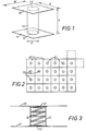
- Figure 1 shows a modular unit comprising spaced first and second generally co-extensive layers 10 and 11, each including a circular or other region 12, the edges of the respective regions 12 being joined by a cylindrical or other tubular element 13.
- the module can be regarded as having a spool-shaped structure with square flanges, though in practice the webs 10 and 11 constituting these "flanges" can be square or rectangular or can have any other suitable shape, e.g. hexagonal.
- the module is shown in Figure 1 as having rectangular layers 10 and 11 which measure W units in one direction and X units in the other, the layers 10 and 11 are spaced Y units apart, which also is the length of the tubular element 13, whilst the latter is shown as a cylindrical tube having a diameter of Z units.
- the dimensions W, X, Y and Z are interrelated, as shown, but are variable to suit the size of the desired module and the corresponding dimensions of a fillable structure made by assembling many of them, in the manner shown in Figure 2.
- the layers 10, 11 are joined together in regular patchwork fashion and it will be clear that in practice difficulty would normally arise if shapes other than square or rectangular are used, though such other shapes are not excluded. It is also possible to assemble modules of the principle illustrated in Figure 1 with blank portions of the layers, if desired.
- the regions 12 can be of the same construction as the rest of the layers 10, 11 or they can be of a different construction, e.g. being woven to have a more open mesh.
- Figure 3 shows a cross-section through a module or the portion of a shutter containing a tubular element 13, where the latter is supported and reinforced by a member 14 in the form of a helical rod or wire.
- the supporting and reinforcing member 14 holds the tubular element 13 open and also retains the layers 10, 11 in their fully-spaced relationship.
- the supporting member 14 can be put into position in the tubular element 13 before, during or after assembly of the flexible components 10, 11 and 13 constituting the shutter per se or the shutter module.
- the member 14 can be located in the web portion used to make the tubular element 13, which is then attached at its ends to the layers 10 and 11.
- Another procedure is to attach the tubular element 13 to one of the layers 10, 11, insert the supporting member 14 into the pocket formed by the element 13 and then attach the latter to the other of the layers 10, 11.
- a further possibility is to assemble the flexible components and cut into or cut away the region 12 in the layer 10 or 11. This is satisfactory, especially in the case where the cut or removed parts are in the layer which is underneath, i.e. contacts the ground, when the shutter is installed.
- Yet another possibility is to install the supports 14 after the other components have been assembled, by passing the support 14 through the part forming the region 12 at one end of the tubular pocket.
- the helical form of the supporting member 14 is particularly suitable for this mode of assembly, as it can be wound through a hole made, say in the layer 10, provided with an eyelet, made as a small aperture in the layer, or even formed by spreading out the yarns it is woven from.
- This member 15 takes the form of a portion of a flexible spun-bonded plastics sheet material, consisting therefore of a mass of interconnected filaments and so having a highly open structure, formed into a cylindrical shape which, when located in position in the tubular element 13 as shown, serves like the member 14 in Fig. 3 to hold the structure open.
- the cylinder can be made very simply by spirally rolling a long rectangular portion of the spun-bonded plastics sheet material.
- all the flexible materials used in forming the layers 10, 11 and the tubular elements 13 of the structure are at least partly porous.
- the settable compositions used to fill the structures in one general embodiment of the invention, is prevented from penetrating through the walls of the tubular elements 13, though a degree of penetration may be desirable in some circumstances.
- some of the tubular elements allow the settable composition to pass into them so that the spaces inside these parts of the structure become filled.
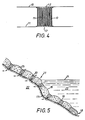
- a flexible shutter of the invention in use, as illustrated in Figure 5, comprises a pair of generally co-extensive layers.
- One such layer is shown at 16 in Fig. 5 and the other at 17.
- At spaced locations, over the resulting mattress or blanket-like structure, opposed regions in the layers 16, 17 are joined by tubular elements 19.
- a supporting and reinforcing member 20 e.g. such as shown in Fig. 3 or in Fig. 4 or some other suitable structure.
- the flexible shutter shown generally at 21 is used to protect the ground 22, e.g. a foreshore or bank, from the erosive effect of wave and other action of a body of water, shown at 23.
- the shutter 21 is laid upon the ground 22 over the entire area requiring protection.
- a liquid or plastic state settable composition e.g. a pumpable concrete mix, is then introduced through access ports (not shown) in the periphery of the shutter 21 at a convenient location above the water level 24.
- the mix fills the entire space between the layers 16, 17 leaving the supported tubular elements 19 open.
- These can serve for receiving fixing members (not shown) for locating the shutter 21 in place, such fixing members being positioned through selected ones of the tubular elements 19 and being driven into the ground 22.
- the concrete mix expands the fillable space and sets to a concrete structure indicated at 25, whose underside conforms to the shape of the ground 22 and whose top side forms the actual interface with the water 23.
- Ground water in the ground 22 is allowed to drain into the water space and, unlike many prior art shutters, is not held back, causing difficulty, as it can find its way through the supported apertures defined by the tubular elements 19.
- a major disadvantage of many known flexible shutters, whereby water seepage tends to lift or undermine them, is thus eliminated or reduced to acceptable levels.
- the support provided by the steel helixes 14, coiled spun-bonded plastics sheets 15 or other members located in the tubes greatly rigidifies the structure and enables it to have a thickness greater than can be achieved with prior structures whilst using conventional concrete mixes.
- the finished structure as shown in Fig. 5 can have a thickness well in excess of 300 mm, if required.
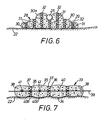
- this shows an embodiment in which the shutter is employed to support a pipeline 26 either over the ground or the sea-bed, indicated at 22.
- the shutter in this embodiment is made to have a length such that it can extend along the intended course of the pipeline 26 or at least those parts which are under water or where the terrain is swampy or otherwise difficult.
- the mattress made from the shutter has the great advantage of giving ade- qua t e support for the load represented by the pipeline 26 and its contents, by virtue of the way in which the shutter is constructed, which causes its internal reinforcing to support the top layer of fabric.
- the mattress of Fig. 6, indicated generally at 28, can have a height to width ratio of as much as 1:3.
- the shutter from which it is made consists of a bottom layer 29 joined at intervals across its width to the bottom edges of upper layer components 30, each of which extends upwardly and inwardly so that its upper edge is joined to an intermediate part of the next inner component 30.
- the central component 30a upon which the pipeline 26 rests can be a large and integral strip as shown. Where each component 30 joins the next, rows of pockets or tubular elements 31 are provided and three rows of such tubular elements 31 are included in the central component 30a.
- These tubular elements 31 contain supports 32 of open structure, e.g. helical springs.
- Drainage holes are desirable, at least at some places in the pipeline supporting mattress 28, for instance so as to allow ground water to pass through the mattress 28, and these can be formed by constructing some of the tubular elements 31 so that they do not allow access to the filling mix, when the structure is being installed and filled.
- a mattress 33 consists of a lower layer 34 and a co-extensive upper layer 35 between which tubular elements 36 are joined.
- Each element 36 contains a supporting member 37 in the form of a spiral or helical spring or a wound spun-plastics component, as shown in Fig. 3 or Fig. 4 respectively.
- the concrete in- filling 38 occupies the internal space of the shutter forming the mattress 33 except for the tubular elements 36.
- Additional internal reinforcement is provided, in the form of reinforcing wires, rods, ties or bars 39, which pass through the mattress 33 approximately in its mid-plane, preferably by passing through and being joined to the associated transverse rows of supporting members 37.
- Further reinforcing wires, rods, ties or bars 40 run longitudinally of the mattress 33. As shown, these are also approximately in the mid-plane of the mattress 33 and run, as shown for the reinforcing members 40a, through the longitudinal rows of the supporting members 37 and, as shown for the reinforcing members 40b, between such rows. A mesh-like or grid-like assembly of transverse and longitudinal reinforcing bars or other reinforcing members 40 is thus given.
- the members 40 are preferably joined together at their crossing points, as indicated at 41, for additional strength.
- the detailed construction of the shutter and therefore of the mattress structure made from it, in accordance with this invention depends to a large extent upon the nature and type of situation where reinforcement of the ground is required. It has been found, for instance, that less supporting members are usually sufficient, in a mattress of given construction, when it is to be used on level ground, as compared with inclined ground, e.g. a natural or artificial bank or foreshore.
- the invention thus provides a relatively simple structural principle for flexible shutters, which provides a solution to all the main problems inherent in conventional practice.
Landscapes
- Engineering & Computer Science (AREA)
- General Engineering & Computer Science (AREA)
- Environmental & Geological Engineering (AREA)
- Ocean & Marine Engineering (AREA)
- Mechanical Engineering (AREA)
- Civil Engineering (AREA)
- Structural Engineering (AREA)
- Revetment (AREA)
Claims (5)
Applications Claiming Priority (2)
| Application Number | Priority Date | Filing Date | Title |
|---|---|---|---|
| GB7941658 | 1979-12-03 | ||
| GB7941658 | 1979-12-03 |
Publications (2)
| Publication Number | Publication Date |
|---|---|
| EP0030452A1 EP0030452A1 (fr) | 1981-06-17 |
| EP0030452B1 true EP0030452B1 (fr) | 1984-01-11 |
Family
ID=10509578
Family Applications (1)
| Application Number | Title | Priority Date | Filing Date |
|---|---|---|---|
| EP80304363A Expired EP0030452B1 (fr) | 1979-12-03 | 1980-12-03 | Toile de retenue flexible et renforcée et éléments modulaires pour le façonnage d'une telle toile |
Country Status (2)
| Country | Link |
|---|---|
| EP (1) | EP0030452B1 (fr) |
| DE (1) | DE3066112D1 (fr) |
Cited By (1)
| Publication number | Priority date | Publication date | Assignee | Title |
|---|---|---|---|---|
| AU2012202940B2 (en) * | 2005-05-26 | 2015-03-26 | Officine Maccaferri S.P.A. | A lightweight protection element and filter of the mattress type |
Families Citing this family (6)
| Publication number | Priority date | Publication date | Assignee | Title |
|---|---|---|---|---|
| NL1007305C2 (nl) * | 1997-10-17 | 1999-04-20 | Handelmaatschappij De Keerkrin | Werkwijze voor het versterken van dijken. |
| DE10349686B4 (de) * | 2003-10-21 | 2009-10-08 | Universität Rostock | Auflastfilter |
| KR100565953B1 (ko) | 2003-12-23 | 2006-03-30 | 대홍종합건설(주) | 자연석을 이용한 하천의 취입보 축조공법 |
| ITBO20050363A1 (it) * | 2005-05-26 | 2006-11-27 | Maccaferri Spa Off | Elemento leggero di protezione filtro del tipo a materasso |
| JP7185410B2 (ja) * | 2018-03-12 | 2022-12-07 | 大嘉産業株式会社 | 布型枠 |
| CN117721758A (zh) * | 2023-12-25 | 2024-03-19 | 无锡申湖织造有限公司 | 一种机织一次成型自带滤水点的简易模袋 |
Citations (6)
| Publication number | Priority date | Publication date | Assignee | Title |
|---|---|---|---|---|
| US3425228A (en) * | 1967-10-10 | 1969-02-04 | Tech Inc Const | Fabric forms for concrete structures |
| US3524320A (en) * | 1967-01-23 | 1970-08-18 | Lee A Turzillo | Method of protecting areas of an earth situs against scour |
| FR2255803A5 (fr) * | 1973-12-19 | 1975-07-18 | Porraz Jimenez | |
| FR2297959A1 (fr) * | 1975-01-17 | 1976-08-13 | Porraz Mauricio | Perfectionnements aux elements modulaires de construction d'ouvrages hydrauliques et subaquatique |
| FR2352107A1 (fr) * | 1976-05-21 | 1977-12-16 | Porraz J L Mauricio | Element modulaire compose d'une enveloppe souple destinee a etre remplie, sur le lieu d'utilisation, d'une matiere solide injectee sous pression, et assemblage de tels elements en vue de la construction d'ouvrages hydrauliques ou subaquatiques |
| US4154061A (en) * | 1977-07-21 | 1979-05-15 | Construction Techniques, Inc. | Fabric forms for concrete |
-
1980
- 1980-12-03 DE DE8080304363T patent/DE3066112D1/de not_active Expired
- 1980-12-03 EP EP80304363A patent/EP0030452B1/fr not_active Expired
Patent Citations (6)
| Publication number | Priority date | Publication date | Assignee | Title |
|---|---|---|---|---|
| US3524320A (en) * | 1967-01-23 | 1970-08-18 | Lee A Turzillo | Method of protecting areas of an earth situs against scour |
| US3425228A (en) * | 1967-10-10 | 1969-02-04 | Tech Inc Const | Fabric forms for concrete structures |
| FR2255803A5 (fr) * | 1973-12-19 | 1975-07-18 | Porraz Jimenez | |
| FR2297959A1 (fr) * | 1975-01-17 | 1976-08-13 | Porraz Mauricio | Perfectionnements aux elements modulaires de construction d'ouvrages hydrauliques et subaquatique |
| FR2352107A1 (fr) * | 1976-05-21 | 1977-12-16 | Porraz J L Mauricio | Element modulaire compose d'une enveloppe souple destinee a etre remplie, sur le lieu d'utilisation, d'une matiere solide injectee sous pression, et assemblage de tels elements en vue de la construction d'ouvrages hydrauliques ou subaquatiques |
| US4154061A (en) * | 1977-07-21 | 1979-05-15 | Construction Techniques, Inc. | Fabric forms for concrete |
Cited By (1)
| Publication number | Priority date | Publication date | Assignee | Title |
|---|---|---|---|---|
| AU2012202940B2 (en) * | 2005-05-26 | 2015-03-26 | Officine Maccaferri S.P.A. | A lightweight protection element and filter of the mattress type |
Also Published As
| Publication number | Publication date |
|---|---|
| EP0030452A1 (fr) | 1981-06-17 |
| DE3066112D1 (en) | 1984-02-16 |
Similar Documents
| Publication | Publication Date | Title |
|---|---|---|
| US5641244A (en) | Revetment, revetment system and method for the banks of waterways | |
| US4102137A (en) | Coating and protective device | |
| US3670504A (en) | Fabric containment constructions | |
| US3474626A (en) | Method and means for protecting beaches | |
| BRPI0902767A2 (pt) | tubo de geotêxtil com extremidades achatadas | |
| EP0030452B1 (fr) | Toile de retenue flexible et renforcée et éléments modulaires pour le façonnage d'une telle toile | |
| US5040572A (en) | Revetment mattress | |
| CA2610191C (fr) | Element de protection leger et filtre de type matelas | |
| US11773554B2 (en) | Erosion prevention | |
| JP6573505B2 (ja) | 施工セル構造体及びその施工方法 | |
| JPH0552364B2 (fr) | ||
| JP2866225B2 (ja) | 地盤補強工法 | |
| KR100959677B1 (ko) | 친환경 매트리스형 돌망태 및 그 설치 방법 | |
| WO2021229205A1 (fr) | Améliorations de la prévention de l'érosion et concernant la prévention de l'érosion | |
| RU2801714C1 (ru) | Подпорная стенка армогрунтовой конструкции для защиты прибрежных зон от обрушения и размыва | |
| WO1992010615A1 (fr) | Conditionnement des sols | |
| RU2801750C1 (ru) | Способ возведения подпорной стенки комбинированной конструкции для защиты прибрежных зон от размыва | |
| GB2167795A (en) | Flexible revetment panel | |
| JPH073013B2 (ja) | 土木工事用多重織シ−ト | |
| EP3425116B1 (fr) | Système anti-érosion en matériau géosynthétique | |
| ES2806683T3 (es) | Sistema contra la erosión compuesto de material geosintético | |
| AU603465B2 (en) | Revetment mattressing | |
| GB2083115A (en) | Reinforced flexible shutters | |
| JP2007154476A (ja) | 河川敷のブランケット構造及びこれを構築する河川敷のブランケット工法 | |
| JPH0255566B2 (fr) |
Legal Events
| Date | Code | Title | Description |
|---|---|---|---|
| PUAI | Public reference made under article 153(3) epc to a published international application that has entered the european phase |
Free format text: ORIGINAL CODE: 0009012 |
|
| AK | Designated contracting states |
Designated state(s): BE CH DE FR GB IT LI NL |
|
| 17P | Request for examination filed |
Effective date: 19810924 |
|
| ITF | It: translation for a ep patent filed | ||
| RBV | Designated contracting states (corrected) |
Designated state(s): BE CH DE FR GB IT LI NL |
|
| GRAA | (expected) grant |
Free format text: ORIGINAL CODE: 0009210 |
|
| AK | Designated contracting states |
Designated state(s): BE CH DE FR GB IT LI NL |
|
| REF | Corresponds to: |
Ref document number: 3066112 Country of ref document: DE Date of ref document: 19840216 |
|
| ET | Fr: translation filed | ||
| PLBE | No opposition filed within time limit |
Free format text: ORIGINAL CODE: 0009261 |
|
| STAA | Information on the status of an ep patent application or granted ep patent |
Free format text: STATUS: NO OPPOSITION FILED WITHIN TIME LIMIT |
|
| PG25 | Lapsed in a contracting state [announced via postgrant information from national office to epo] |
Ref country code: LI Effective date: 19841231 Ref country code: CH Effective date: 19841231 Ref country code: BE Effective date: 19841231 |
|
| 26N | No opposition filed | ||
| BERE | Be: lapsed |
Owner name: S.A. UCO N.V. Effective date: 19841203 |
|
| PG25 | Lapsed in a contracting state [announced via postgrant information from national office to epo] |
Ref country code: NL Effective date: 19850701 |
|
| NLV4 | Nl: lapsed or anulled due to non-payment of the annual fee | ||
| PG25 | Lapsed in a contracting state [announced via postgrant information from national office to epo] |
Ref country code: FR Free format text: LAPSE BECAUSE OF NON-PAYMENT OF DUE FEES Effective date: 19850830 |
|
| REG | Reference to a national code |
Ref country code: CH Ref legal event code: PL |
|
| PG25 | Lapsed in a contracting state [announced via postgrant information from national office to epo] |
Ref country code: DE Effective date: 19850903 |
|
| REG | Reference to a national code |
Ref country code: FR Ref legal event code: ST |
|
| PGFP | Annual fee paid to national office [announced via postgrant information from national office to epo] |
Ref country code: GB Payment date: 19891231 Year of fee payment: 10 |
|
| PG25 | Lapsed in a contracting state [announced via postgrant information from national office to epo] |
Ref country code: GB Effective date: 19901203 |
|
| GBPC | Gb: european patent ceased through non-payment of renewal fee |