EP0030455A1 - Amortisseur sensible au déplacement - Google Patents
Amortisseur sensible au déplacement Download PDFInfo
- Publication number
- EP0030455A1 EP0030455A1 EP80304368A EP80304368A EP0030455A1 EP 0030455 A1 EP0030455 A1 EP 0030455A1 EP 80304368 A EP80304368 A EP 80304368A EP 80304368 A EP80304368 A EP 80304368A EP 0030455 A1 EP0030455 A1 EP 0030455A1
- Authority
- EP
- European Patent Office
- Prior art keywords
- piston
- damper
- cylinder
- compression
- rebound
- Prior art date
- Legal status (The legal status is an assumption and is not a legal conclusion. Google has not performed a legal analysis and makes no representation as to the accuracy of the status listed.)
- Ceased
Links
- 238000006073 displacement reaction Methods 0.000 title description 2
- 238000007906 compression Methods 0.000 claims abstract description 27
- 230000006835 compression Effects 0.000 claims abstract description 26
- 238000013016 damping Methods 0.000 claims description 12
- 239000012530 fluid Substances 0.000 claims description 8
- 239000007789 gas Substances 0.000 description 13
- 238000010276 construction Methods 0.000 description 6
- 239000006096 absorbing agent Substances 0.000 description 3
- 230000035939 shock Effects 0.000 description 3
- IJGRMHOSHXDMSA-UHFFFAOYSA-N Atomic nitrogen Chemical compound N#N IJGRMHOSHXDMSA-UHFFFAOYSA-N 0.000 description 2
- 239000000725 suspension Substances 0.000 description 2
- 238000006243 chemical reaction Methods 0.000 description 1
- 230000003467 diminishing effect Effects 0.000 description 1
- 239000000428 dust Substances 0.000 description 1
- 230000000694 effects Effects 0.000 description 1
- 239000000839 emulsion Substances 0.000 description 1
- 229910052757 nitrogen Inorganic materials 0.000 description 1
- 230000037452 priming Effects 0.000 description 1
- 230000000750 progressive effect Effects 0.000 description 1
- 230000003068 static effect Effects 0.000 description 1
Images


Classifications
-
- F—MECHANICAL ENGINEERING; LIGHTING; HEATING; WEAPONS; BLASTING
- F16—ENGINEERING ELEMENTS AND UNITS; GENERAL MEASURES FOR PRODUCING AND MAINTAINING EFFECTIVE FUNCTIONING OF MACHINES OR INSTALLATIONS; THERMAL INSULATION IN GENERAL
- F16F—SPRINGS; SHOCK-ABSORBERS; MEANS FOR DAMPING VIBRATION
- F16F9/00—Springs, vibration-dampers, shock-absorbers, or similarly-constructed movement-dampers using a fluid or the equivalent as damping medium
- F16F9/32—Details
- F16F9/48—Arrangements for providing different damping effects at different parts of the stroke
-
- F—MECHANICAL ENGINEERING; LIGHTING; HEATING; WEAPONS; BLASTING
- F16—ENGINEERING ELEMENTS AND UNITS; GENERAL MEASURES FOR PRODUCING AND MAINTAINING EFFECTIVE FUNCTIONING OF MACHINES OR INSTALLATIONS; THERMAL INSULATION IN GENERAL
- F16F—SPRINGS; SHOCK-ABSORBERS; MEANS FOR DAMPING VIBRATION
- F16F9/00—Springs, vibration-dampers, shock-absorbers, or similarly-constructed movement-dampers using a fluid or the equivalent as damping medium
- F16F9/32—Details
- F16F9/34—Special valve constructions; Shape or construction of throttling passages
Definitions
- This invention relates to displacement conscious vibration dampers and particularly, but not exclusively relates to shock absorbers for road vehicle suspensions.
- a pressurized hydraulic damper comprises a cylinder, a piston in the cylinder, a piston rod connected to the piston and extending out of one end of the cylinder, longitudinally spaced ports extending through the cylinder, bypass passage means interconnecting the ports, the ports being positioned so that at least one is obturated by the piston during movement of the piston in its working stroke to vary the flow resistance from one side of the piston to the other as the position of the piston in its stroke varies, and valves in the piston or in the bypass or in both the piston and the bypass, these valves constituting the only damping valves of the damper.
- the invention is particularly applicable to dampers in which the pressurisation is achieved by gas under pressure, either with the gas in direct contact with the hydraulic fluid or separated therefrom by a movable wall such as a floating piston but the pressurisation could alternatively be achieved by a movable wall such as a floating piston acted on by a mechanical spring.
- a damping valve is a variable damping orifice. It is usually used either alone or in combination with other damping valve(s) and/or non-variable damping orifice(s) to produce a predetermined pressure to flow relationship that is different to the inherent relationship for a non-variable damping orifice.
- a damping orifice allows hut restricts flow of fluid for the purpose of diminishing, by conversion into heat, some at least of the pressure and kinetic energy in the fluid so as to control the movement of, and/or forces generated in, a device the movement of which causes the fluid flow.
- the damper of the invention may be considered as having only two hydraulic fluid volumes which- are connected by not more than two groups of flow paths, one group through or around the piston Ci.e. the piston compression and rebound valves and any bleed paths there may be through or around the piston) and another bypassing at least a part of the working cylinder which can be entered by the piston.
- the bypass passage is unvalved and then, for any given piston position, the bypass affects flow during both compression and rebound substantially equally although the hydraulic resistance/velocity characteristics will be different at different piston positions. This is not the case with the damper described in British Patent Specification No. 1 125 104 in which there is a reservoir connected to one of the cylinder chambers through a base valve assembly providing separate valves for flow into and flow out of the reservoir.
- the bypass circuit in this construction will always have a greater relative effect on the rebound characteristic of the damper than on compression; the base valve must provide a sufficiently high resistance to ensure filling of the working cylinder on the piston rod side of the piston in all positions of operation, i.e. including those in which resistance to flow from below to above the piston through and around the piston and through the bypass circuit is maximal.
- the damper of the invention may be considered as having only two hydraulic fluid volumes which are connected by two groups of flow paths.
- Each of these volumes will be constituted, at least partly, by space in the cylinder lying on one side or the other of the piston but may be supplemented by space lying outside the cylinder and connected to the space lying inside the cylinder by passage means without valves.
- Such an external space may be provided by an annular chamber surrounding the cylinder.
- a hydraulic damper comprises an inner cylinder, an outer cylinder surrounding the inner cylinder and providing the outside surface of the damper, an annular chamber bounded by the outside of the inner cylinder and the inside of the outer cylinder, a piston in the inner cylinder and having compression and rebound valves to allow but restrict flow through the piston, a piston rod connected to the piston and extending out of one end of the cylinder, a floating piston in the inner cylinder adjacent the other end of the inner cylinder, a pressurized gas charge in the inner cylinder on the side of the floating piston remote from the valved piston, and longitudinally spaced ports extending through the inner cylinder and so positioned that at least one is obturated by the valved piston during movement of the piston in its working stroke to vary the resistance to flow from one side of the valved piston to the other through the annular chamber during movement of the valved piston in its working stroke.
- the damper 10 comprises an outer cylinder 11 and an inner cylinder 12 providing a cylinder chamber 13 and an annular chamber 14 which are closed at one end by an end fitting 15 having attachment means 16 for attachment of the damper to either the sprung or unsprung mass of a vehicle and at the other end by an end fitting 16 constituting a guide for a piston rod 17 the outer end of which has attachment means (not shown) for attachment of the damper to the unsprung or sprung mass of the vehicle.
- the piston rod 17 carries a dust cover 18.
- the cylinder chamber 13 is divided by a floating piston 19 into a gas space 13a on the side adjacent the end fitting 15 and an oil space on the other side. Oil (hydraulic fluid) is introduced into the oil space before the floating piston 19 and end fitting 15 are fitted. Pressurized gas is then admitted to the gas space through a check valve 21.
- the inner end of the piston rod 17 is formed with a spigot 23 on which a piston 24 is secured by a nut 25.
- the piston divides the oil space into a first chamber 13b remote from the piston rod and a second chamber 13c surrounding the piston rod.
- the piston is formed with a first ring of passages 26 which lead from the first to the second chamber and are closed by a compression valve 27 constituted by a stack of spring washers.
- the piston is also formed with a second ring of passages 28 which lead from the second to the first chamber and are closed by a rebound valve 29 also constituted by a stack of spring washers. Either or both stacks may have small bleed notches as is conventional.
- The'annular chamber 14 between the inner and outer cylinders constitutes a bypass passage around the piston 24 and it is connected to the oil space by a first port 31 normally open to the first oil chamber 13b and a series of axially spaced second ports 32 (in this case two ports) normally open to the second oil chamber 13a.
- the damper described may be used for various purposes.
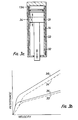
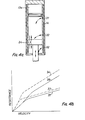
- One such purpose is to give increased damping as the vehicle load is increased from unladen ( Figures 4a and 4b), through partly laden ( Figures 2a and 2b) to fully laden ( Figures 3a and 3b); this is particularly valuable where the vehicle is fitted with variable rate springs.
- Another purpose is to provide a progressive hydraulic compression stop.
- the first port 31 is a small port and contributes to resistance to flow' through the bypass 14 and hence to damping and the lowermost of the second ⁇ ports 32 is large but in an alternative construction this arrangement is reversed.
- the damper shown in Figure 5 is a pressurized two tube shock absorber having many similarities with that shown in Figure 1 and similar parts will be given the same references with the addition of a prime.
- the outer cylinder 11' is surrounded by a tube 51 providing an annular chamber 52 which is in communication with the oil space 13'a through a bore 53 in the end fitting 15'. There is no separate gas space, the oil and gas forming some emulsion in the chamber 52.
- Priming notches 54 are provided in the end closure 16' through which any gas present in the oil space 13'c can be expelled into the chamber 52 during stroking of the damper.
- the piston rod 17' it is necessary for the piston rod 17' to be at the top but the damper can be modified so as to be usable in any attitude by including in the chamber 52 a floating piston separating a gas space at the piston rod end of the chamber from an oil space.
- the bypass passage is unvalved and the piston has both compression and rebound valves.
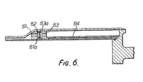
- valved by-pass passage construction is shown in Figure 6.
- the valve comprises two valve seat members 61 and 63 having corresponding valve seats 61a and 63a a valve disc 62 serving for both compression and rebound, and a clamping tube 64, all of which components are generally annular.
- the inner periphery of the disc is lifted from the valve seat 61a while on compression movement, the outer periphery of the disc is lifted from the valve seat 63a.
- Either or both of the valve seats may have bleed notches (not shown) cut in them.
Landscapes
- Engineering & Computer Science (AREA)
- General Engineering & Computer Science (AREA)
- Mechanical Engineering (AREA)
- Fluid-Damping Devices (AREA)
- Vehicle Body Suspensions (AREA)
Applications Claiming Priority (2)
| Application Number | Priority Date | Filing Date | Title |
|---|---|---|---|
| GB7941856A GB2064710B (en) | 1979-12-04 | 1979-12-04 | Displacement conscious dampers |
| GB7941856 | 1979-12-04 |
Publications (1)
| Publication Number | Publication Date |
|---|---|
| EP0030455A1 true EP0030455A1 (fr) | 1981-06-17 |
Family
ID=10509607
Family Applications (1)
| Application Number | Title | Priority Date | Filing Date |
|---|---|---|---|
| EP80304368A Ceased EP0030455A1 (fr) | 1979-12-04 | 1980-12-03 | Amortisseur sensible au déplacement |
Country Status (6)
| Country | Link |
|---|---|
| EP (1) | EP0030455A1 (fr) |
| JP (1) | JPS5690140A (fr) |
| BE (1) | BE886502A (fr) |
| FR (1) | FR2479386B1 (fr) |
| GB (1) | GB2064710B (fr) |
| IT (1) | IT1146971B (fr) |
Cited By (1)
| Publication number | Priority date | Publication date | Assignee | Title |
|---|---|---|---|---|
| EP0280904A1 (fr) * | 1987-03-02 | 1988-09-07 | AROS Hydraulik GmBH | Amortisseur hydraulique de chocs et d'oscillations |
Families Citing this family (3)
| Publication number | Priority date | Publication date | Assignee | Title |
|---|---|---|---|---|
| RO118546B1 (ro) * | 1999-06-04 | 2003-06-30 | Adrian Ioan Niculescu | Amortizor hidraulic |
| CN110939677A (zh) * | 2019-11-29 | 2020-03-31 | 浙江雷宸智能科技有限公司 | 臂力器阻尼 |
| CN117145915B (zh) * | 2023-09-13 | 2026-02-13 | 深圳京西智行全球研发创新中心有限公司 | 磁流变阻尼器及其操作方法 |
Citations (1)
| Publication number | Priority date | Publication date | Assignee | Title |
|---|---|---|---|---|
| GB1125104A (en) * | 1965-10-13 | 1968-08-28 | British Railways Board | Improvements relating to variable rate dampers |
Family Cites Families (11)
| Publication number | Priority date | Publication date | Assignee | Title |
|---|---|---|---|---|
| NL105561C (fr) * | 1956-02-24 | |||
| US3127958A (en) * | 1961-06-30 | 1964-04-07 | Ford Motor Co | Shock absorber with improved relief valve structure |
| US3213973A (en) * | 1964-06-04 | 1965-10-26 | Ford Motor Co | Hydraulic shock absorber having external jounce and rebound passages |
| US3381952A (en) * | 1965-10-23 | 1968-05-07 | Robert A. Stubblefield | Load-leveling shock absorber |
| US3446317A (en) * | 1967-08-28 | 1969-05-27 | Efdyn Corp | Adjustable shock absorber |
| GB1229880A (fr) * | 1968-01-23 | 1971-04-28 | ||
| GB1239667A (fr) * | 1969-04-18 | 1971-07-21 | ||
| GB1351333A (en) * | 1971-07-27 | 1974-04-24 | Ibis Engineers Ltd | Snubbing devices or shock absorbers |
| US3750856A (en) * | 1971-12-09 | 1973-08-07 | G Kenworthy | Adjustable, pressure compensating shock absorber/buffer |
| US3837445A (en) * | 1973-01-30 | 1974-09-24 | Monroe Belgium Nv | Piston assembly for a shock absorber |
| US4114735A (en) * | 1976-03-15 | 1978-09-19 | Tokico Ltd. | Hydraulic damper and valve structure |
-
1979
- 1979-12-04 GB GB7941856A patent/GB2064710B/en not_active Expired
-
1980
- 1980-12-03 EP EP80304368A patent/EP0030455A1/fr not_active Ceased
- 1980-12-04 IT IT50311/80A patent/IT1146971B/it active
- 1980-12-04 BE BE0/203050A patent/BE886502A/fr not_active IP Right Cessation
- 1980-12-04 FR FR8025752A patent/FR2479386B1/fr not_active Expired
- 1980-12-04 JP JP17030980A patent/JPS5690140A/ja active Pending
Patent Citations (1)
| Publication number | Priority date | Publication date | Assignee | Title |
|---|---|---|---|---|
| GB1125104A (en) * | 1965-10-13 | 1968-08-28 | British Railways Board | Improvements relating to variable rate dampers |
Cited By (1)
| Publication number | Priority date | Publication date | Assignee | Title |
|---|---|---|---|---|
| EP0280904A1 (fr) * | 1987-03-02 | 1988-09-07 | AROS Hydraulik GmBH | Amortisseur hydraulique de chocs et d'oscillations |
Also Published As
| Publication number | Publication date |
|---|---|
| BE886502A (fr) | 1981-06-04 |
| IT8050311A0 (it) | 1980-12-04 |
| FR2479386B1 (fr) | 1987-02-06 |
| GB2064710B (en) | 1984-05-10 |
| GB2064710A (en) | 1981-06-17 |
| IT1146971B (it) | 1986-11-19 |
| FR2479386A1 (fr) | 1981-10-02 |
| JPS5690140A (en) | 1981-07-22 |
Similar Documents
| Publication | Publication Date | Title |
|---|---|---|
| US6220409B1 (en) | Stroke dependent bypass | |
| EP1158202B2 (fr) | Canal de passage variable, accordable indépendamment | |
| EP1664578B1 (fr) | Derivation dependant de la course | |
| EP2258961B1 (fr) | Amortisseur de véhicule | |
| EP2158416B1 (fr) | Purge de jonction | |
| EP1664582B1 (fr) | Amortissement en fonction de la course d'un piston | |
| US11524544B2 (en) | Spring-absorber system with variable spring rate | |
| EP0607545B1 (fr) | Amortisseur | |
| US20080129000A1 (en) | Hydraulic System for a Vehicle Suspension | |
| US20030051957A1 (en) | Shock absorber with a floating piston | |
| GB2402990A (en) | Twin piston shock absorber | |
| US3232390A (en) | Shock absorber including spring loaded valve in piston | |
| EP1167810B1 (fr) | Amortisseur de chocs adaptable à basse vitesse, comprenant une plaque à orifices | |
| EP1113186A2 (fr) | Soupape à disque comprenant des canaux de passages variables | |
| US20060175166A1 (en) | Controllable piston valve and /or flat valve for a vibration damper | |
| EP1312827A2 (fr) | Elément flottant de blocage d'un orifice dans un piston d'amortisseur | |
| CN114909421B (zh) | 阻尼器组件 | |
| CN114599894A (zh) | 平衡式连续半主动阻尼器 | |
| JP2007506923A (ja) | 電子流動学的又は磁性流動学的に制御された液圧絞り | |
| GB2064710A (en) | Displacement conscious dampers | |
| JPH10339345A (ja) | 液圧緩衝装置 | |
| CA1181102A (fr) | Amortisseur volumetrique | |
| US6148969A (en) | Frequency dependant damper | |
| US5647461A (en) | Adjustable piston valve damper | |
| US20220412425A1 (en) | Vehicle Shock Absorber |
Legal Events
| Date | Code | Title | Description |
|---|---|---|---|
| PUAI | Public reference made under article 153(3) epc to a published international application that has entered the european phase |
Free format text: ORIGINAL CODE: 0009012 |
|
| AK | Designated contracting states |
Designated state(s): AT CH DE NL SE |
|
| 17P | Request for examination filed |
Effective date: 19811127 |
|
| PLBE | No opposition filed within time limit |
Free format text: ORIGINAL CODE: 0009261 |
|
| PLAA | Information modified related to event that no opposition was filed |
Free format text: ORIGINAL CODE: 0009299DELT |
|
| 26N | No opposition filed | ||
| ET | Fr: translation filed | ||
| STAA | Information on the status of an ep patent application or granted ep patent |
Free format text: STATUS: THE APPLICATION HAS BEEN REFUSED |
|
| 18R | Application refused |
Effective date: 19831211 |
|
| RIN1 | Information on inventor provided before grant (corrected) |
Inventor name: DUCKETT, WILLIAM ARTHUR Inventor name: ECKERSLEY, JOHN STANELY |