EP0030674A1 - Dispositif de changement d'outils pour machine-outils, en particulier pour aléseuses-fraiseuses horizontales - Google Patents
Dispositif de changement d'outils pour machine-outils, en particulier pour aléseuses-fraiseuses horizontales Download PDFInfo
- Publication number
- EP0030674A1 EP0030674A1 EP80107520A EP80107520A EP0030674A1 EP 0030674 A1 EP0030674 A1 EP 0030674A1 EP 80107520 A EP80107520 A EP 80107520A EP 80107520 A EP80107520 A EP 80107520A EP 0030674 A1 EP0030674 A1 EP 0030674A1
- Authority
- EP
- European Patent Office
- Prior art keywords
- arm
- changing device
- piston
- tool changing
- axis
- Prior art date
- Legal status (The legal status is an assumption and is not a legal conclusion. Google has not performed a legal analysis and makes no representation as to the accuracy of the status listed.)
- Granted
Links
- 238000003801 milling Methods 0.000 title claims abstract description 7
- 230000033001 locomotion Effects 0.000 claims abstract description 47
- 238000005553 drilling Methods 0.000 claims description 14
- 230000008878 coupling Effects 0.000 claims description 6
- 238000010168 coupling process Methods 0.000 claims description 6
- 238000005859 coupling reaction Methods 0.000 claims description 6
- 230000005540 biological transmission Effects 0.000 claims description 2
- 241001416181 Axis axis Species 0.000 claims 1
- 230000000712 assembly Effects 0.000 claims 1
- 238000000429 assembly Methods 0.000 claims 1
- 230000001133 acceleration Effects 0.000 abstract description 2
- 238000005352 clarification Methods 0.000 description 1
- 230000026058 directional locomotion Effects 0.000 description 1
- 230000000694 effects Effects 0.000 description 1
- 238000003754 machining Methods 0.000 description 1
- 230000001105 regulatory effect Effects 0.000 description 1
Images




Classifications
-
- B—PERFORMING OPERATIONS; TRANSPORTING
- B23—MACHINE TOOLS; METAL-WORKING NOT OTHERWISE PROVIDED FOR
- B23Q—DETAILS, COMPONENTS, OR ACCESSORIES FOR MACHINE TOOLS, e.g. ARRANGEMENTS FOR COPYING OR CONTROLLING; MACHINE TOOLS IN GENERAL CHARACTERISED BY THE CONSTRUCTION OF PARTICULAR DETAILS OR COMPONENTS; COMBINATIONS OR ASSOCIATIONS OF METAL-WORKING MACHINES, NOT DIRECTED TO A PARTICULAR RESULT
- B23Q3/00—Devices holding, supporting, or positioning work or tools, of a kind normally removable from the machine
- B23Q3/155—Arrangements for automatic insertion or removal of tools, e.g. combined with manual handling
- B23Q3/1552—Arrangements for automatic insertion or removal of tools, e.g. combined with manual handling parts of devices for automatically inserting or removing tools
- B23Q3/1554—Transfer mechanisms, e.g. tool gripping arms; Drive mechanisms therefore
-
- B—PERFORMING OPERATIONS; TRANSPORTING
- B23—MACHINE TOOLS; METAL-WORKING NOT OTHERWISE PROVIDED FOR
- B23Q—DETAILS, COMPONENTS, OR ACCESSORIES FOR MACHINE TOOLS, e.g. ARRANGEMENTS FOR COPYING OR CONTROLLING; MACHINE TOOLS IN GENERAL CHARACTERISED BY THE CONSTRUCTION OF PARTICULAR DETAILS OR COMPONENTS; COMBINATIONS OR ASSOCIATIONS OF METAL-WORKING MACHINES, NOT DIRECTED TO A PARTICULAR RESULT
- B23Q3/00—Devices holding, supporting, or positioning work or tools, of a kind normally removable from the machine
- B23Q3/155—Arrangements for automatic insertion or removal of tools, e.g. combined with manual handling
- B23Q3/1552—Arrangements for automatic insertion or removal of tools, e.g. combined with manual handling parts of devices for automatically inserting or removing tools
- B23Q3/1554—Transfer mechanisms, e.g. tool gripping arms; Drive mechanisms therefore
- B23Q2003/155414—Transfer mechanisms, e.g. tool gripping arms; Drive mechanisms therefore the transfer mechanism comprising two or more grippers
- B23Q2003/155418—Transfer mechanisms, e.g. tool gripping arms; Drive mechanisms therefore the transfer mechanism comprising two or more grippers the grippers moving together
-
- B—PERFORMING OPERATIONS; TRANSPORTING
- B23—MACHINE TOOLS; METAL-WORKING NOT OTHERWISE PROVIDED FOR
- B23Q—DETAILS, COMPONENTS, OR ACCESSORIES FOR MACHINE TOOLS, e.g. ARRANGEMENTS FOR COPYING OR CONTROLLING; MACHINE TOOLS IN GENERAL CHARACTERISED BY THE CONSTRUCTION OF PARTICULAR DETAILS OR COMPONENTS; COMBINATIONS OR ASSOCIATIONS OF METAL-WORKING MACHINES, NOT DIRECTED TO A PARTICULAR RESULT
- B23Q3/00—Devices holding, supporting, or positioning work or tools, of a kind normally removable from the machine
- B23Q3/155—Arrangements for automatic insertion or removal of tools, e.g. combined with manual handling
- B23Q3/1552—Arrangements for automatic insertion or removal of tools, e.g. combined with manual handling parts of devices for automatically inserting or removing tools
- B23Q3/1554—Transfer mechanisms, e.g. tool gripping arms; Drive mechanisms therefore
- B23Q2003/155414—Transfer mechanisms, e.g. tool gripping arms; Drive mechanisms therefore the transfer mechanism comprising two or more grippers
- B23Q2003/155425—Transfer mechanisms, e.g. tool gripping arms; Drive mechanisms therefore the transfer mechanism comprising two or more grippers pivotable
- B23Q2003/155428—Transfer mechanisms, e.g. tool gripping arms; Drive mechanisms therefore the transfer mechanism comprising two or more grippers pivotable about a common axis
-
- Y—GENERAL TAGGING OF NEW TECHNOLOGICAL DEVELOPMENTS; GENERAL TAGGING OF CROSS-SECTIONAL TECHNOLOGIES SPANNING OVER SEVERAL SECTIONS OF THE IPC; TECHNICAL SUBJECTS COVERED BY FORMER USPC CROSS-REFERENCE ART COLLECTIONS [XRACs] AND DIGESTS
- Y10—TECHNICAL SUBJECTS COVERED BY FORMER USPC
- Y10T—TECHNICAL SUBJECTS COVERED BY FORMER US CLASSIFICATION
- Y10T483/00—Tool changing
- Y10T483/17—Tool changing including machine tool or component
- Y10T483/1733—Rotary spindle machine tool [e.g., milling machine, boring, machine, grinding machine, etc.]
- Y10T483/1748—Tool changer between spindle and matrix
- Y10T483/1752—Tool changer between spindle and matrix including tool holder pivotable about axis
- Y10T483/1755—Plural tool holders pivotable about common axis
- Y10T483/1767—Linearly movable tool holders
Definitions
- the invention relates to a tool changing device on machine tools, in particular to a horizontal, boring and milling machine having a boring spindle, having a two-armed interchangeable arm, which is provided with a gripper device and can be rotated about its horizontal axis, on an axially adjustable and around a pivotable to the change arm axis parallel axis pivot arm is rotatably arranged.
- the object of the invention is to create a device in which the operator, provided that the device is designed and works as a semi-automatic device, can get close to a gripper device of the change arm in its initial position in order to use it To be able to exchange tools for a new tool.
- a transfer device from a magazine or the like should be dispensed with, as should the magazine itself, in order to save space, close to the one at the same height or behind the tool carrier, eg. B. the headstock can be arranged.
- the swiveling of the tools over large radii should be avoided as well as large acceleration forces on the change arm and on the tools. Changing tools should save time. Overall, the above requirements should be able to be solved with structurally simple means.
- the invention provides the features of the characterizing part of the main claim. -
- the features of the subclaims serve to improve and further develop the features of the main claim and to identify a particularly advantageous embodiment of the drive means of the swivel arm and the change arm.
- the superimposed swiveling and rotating movement of the swivel arm and the changing arm not only shortens the path of the tools and thus the changing time, but rather the tools are moved in a space-saving way, which allows the parts of the machine to be arranged close to one another.
- the tools are moved on a flat coupling curve, which is not unlike the stretched section of a parabola, or a straight line, as a result of which low centrifugal forces occur, which allow the gripper devices to be designed accordingly.
- the headstock 2 is adjustable in the vertical direction, which has the drilling spindle 3 carrying the machining tool W at its free end.
- the two-armed interchangeable arm 5 and the swivel arm 6 are mounted on a housing 4 on the side of the headstock (FIG. 2).
- the two-armed change arm 5, which is mounted in the middle on the swivel arm, has at its ends the two gripper devices 7, 8, which are known arrangement and type. You are able to hold one tool each in the manner described in more detail below, either insert it into the drill spindle 3 or pull it up or take up a new tool in order to insert it into the drill spindle after rotating the arm 5 and pivoting the arm 6.
- the headstock 2 has on its underside a laterally projecting stand 9 which can be provided with a frame or grating 10 and serves on the one hand as a work place for the operator and on the other hand for receiving control and regulating parts and tools.
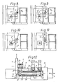
- the arms 5, 6 After opening the gripper device 7, after the holding device of the spindle 3 has grasped the new tool Wa, the arms 5, 6 can again be placed vertically, as shown in FIGS. 10 and 11, and pivoted back into their starting position 5 ', 6' as shown in FIG. 3 and be axially retracted. The rotating and swiveling movements take place in opposite directions and are superimposed. In the starting position 5 ', 6' next to the headstock, the operator can change the tool used and insert a new tool in the arm 5. - The work of the gripper devices 7, 8 is not described in detail; it can be carried out in a known manner.
- the two arms 5, 6 are arranged with their drive parts on a part 16 which by means not shown, for. B. a cylinder piston unit can be pushed back and forth in the direction of the double arrow S (FIG. 12) so that the arms 5, 6 assume the positions 5 ', 6' to 5 "', 6"' can.
- the part 16 has a housing 17 which carries in its rear section two cylinder-piston units 18, 19, the pistons of which are designed as toothed racks 20, 21 or which operate such toothed racks which drive a pinion 22 and a toothing 23 of a rotary bushing 24 which is mounted in the housing 17.
- a drive shaft 25 is mounted horizontally, on which the pinion 22 is attached in a rotationally fixed manner.
- the rotary sleeve 24 has on its front section the swivel arm 6 designed as a hollow part.
- the shaft 25 is mounted at 26 and receives a gear 27 which is connected to the shaft 25 in a rotationally fixed manner.
- a further gear wheel 29 is driven, which is arranged in a rotationally fixed manner on a pivot pin 30, at the front end of which the pivot arm 5 is attached in a rotationally fixed manner.
- the shaft 25 is first held by means of the cylinder-piston unit 19 and the toothed rack 21, so that the toothed wheel 29 is a planet wheel - Movement around the gear 27 representing a stationary sun gear when the bushes 24 is rotated by means of the rack 2o.
- the swivel arm 6 swivels in the direction of arrow F and the arm 5 in the direction of arrow F (FIG. 5).
- the device described above is intended for semi-automatic operation.
- the interchangeable arm is in turn more than twice as long as the swivel arm 6 0 , is rotatably mounted in the middle on the swivel arm and carries the gripper devices 7o and 8 0 at its ends.
- the unused tools can be removed from a magazine M and fed to the drilling spindle 31, or the used tool must be removed from the drilling spindle and fed to the magazine.
- both arms simultaneously perform the same directional movements according to the arrows 0, P into the position according to FIG. 16, in which the gripper device 7o grips the tool W a in the drilling spindle 31, so that both gripper devices 70, 80 each carry a tool and turning the change arm 5o by 180 ° when the arm 60 is at a standstill brings the new tool W n at the level of the spindle 31 and the used tool W a at the level of the magazine (FIG.
- both arms 50, 60 by turning according to arrows Q, R to the position shown in FIG. 18.
- the axial movement necessary for removing or inserting the tools from or into the drilling spindle 31 and into or out of the magazine M takes place after completion of the corresponding pivoting movements and rotary movements of the arms 5 0 , 6 0 .
- the magazine M can be more or less far laterally behind the spindle box 1 03 may be arranged, so the positions of the arms 5 0 that 6o of FIG. 14 and 19 laterally behind the headstock results and only the rotating and pivoting operation of Figure 15 to 18 happens in front of the headstock.
- the rack 2o interacts with the swivel arm 6o, while the rack 21 actuates the change arm 5o.
- the cylinder-piston units 18, 19 are, as in FIG. 12, again of the same type and with the same rods. Since the swivel arm 60 executes a smaller angular movement than the change arm 5o, the transmission ratio of the toothed racks 2 0 , 21 is selected accordingly. Performs the swing arm 6 is 0, as in the example of Figures 13 to 2 0, movements over 9 0 °, and the change arm 5o movements about 18 0 °, then the ratio of the two racks 2 0, 21. 1: 2.
- the cylinder-piston unit 18 is assigned an opposed cylinder-piston unit 104 with a piston rod 106 which is coaxial with the toothed rack 20 and which, when extended against the center position of the swivel arm 60 determine moves the stop, not shown, with the end faces of the parts 20, 106 abutting each other.
- the toothed rack 20 can be fully extended and the arm 60 can thus be pivoted in one direction, the path of the piston in the cylinder-piston unit 18 being limited.
- the rack is moved into its other position, also determined by the end position of the piston in the cylinder 18.
- Fig. 22 illustrates in one example, the movement of the arms 5 0, 6 0, wherein the pivoting arm is shown by two broken lines 6o and moves with his the change arm 5o transmitting end 6oa on the circular arc G in the direction of arrow Z in the clockwise direction.
- the replaceable arm 5o shown in a solid line moves with its end 5oa on the coupling curve 108 in the direction of arrow E, while the end 5ob describes the coupling curve 109. It can be seen that both arm ends 5oa and 5ob run close and almost parallel to planes 11 0 , 111, in which the interchangeable arm 5 o is in its starting position and in its end position.
Landscapes
- Engineering & Computer Science (AREA)
- Mechanical Engineering (AREA)
- Automatic Tool Replacement In Machine Tools (AREA)
Applications Claiming Priority (2)
| Application Number | Priority Date | Filing Date | Title |
|---|---|---|---|
| DE19792950577 DE2950577A1 (de) | 1979-12-15 | 1979-12-15 | Halbautomatische uebergabevorrichtung an werkzeugmaschinen, insbesondere an horizontal-,,bohr- und fraeswerken |
| DE2950577 | 1979-12-15 |
Publications (2)
| Publication Number | Publication Date |
|---|---|
| EP0030674A1 true EP0030674A1 (fr) | 1981-06-24 |
| EP0030674B1 EP0030674B1 (fr) | 1983-12-14 |
Family
ID=6088605
Family Applications (1)
| Application Number | Title | Priority Date | Filing Date |
|---|---|---|---|
| EP80107520A Expired EP0030674B1 (fr) | 1979-12-15 | 1980-12-02 | Dispositif de changement d'outils pour machine-outils, en particulier pour aléseuses-fraiseuses horizontales |
Country Status (3)
| Country | Link |
|---|---|
| US (1) | US4419806A (fr) |
| EP (1) | EP0030674B1 (fr) |
| DE (2) | DE2950577A1 (fr) |
Cited By (1)
| Publication number | Priority date | Publication date | Assignee | Title |
|---|---|---|---|---|
| EP1980360A1 (fr) * | 2007-04-11 | 2008-10-15 | Starragheckert GmbH | Dispositif de changement d'outils et/ou de pièces à usiner |
Families Citing this family (2)
| Publication number | Priority date | Publication date | Assignee | Title |
|---|---|---|---|---|
| DE19605021A1 (de) * | 1996-01-31 | 1997-08-07 | Mannesmann Ag | Maschine zum Trennen von Rohren |
| TW339707U (en) * | 1997-09-02 | 1998-09-01 | he-wei Sun | Improved structure of a center cutter main axis transmission |
Citations (1)
| Publication number | Priority date | Publication date | Assignee | Title |
|---|---|---|---|---|
| DE2629835A1 (de) * | 1976-04-07 | 1977-10-27 | Dixi Sa | Werkzeugwechseleinrichtung fuer automatische werkzeugmaschinen |
Family Cites Families (4)
| Publication number | Priority date | Publication date | Assignee | Title |
|---|---|---|---|---|
| US3348298A (en) * | 1961-08-10 | 1967-10-24 | Kearney & Trecker Corp | Mechanical tool changer for a machine tool |
| DE1951043A1 (de) * | 1969-10-03 | 1971-04-29 | Collet & Engelhard Maschinenfa | Werkzeugwechseleinrichtung fuer Waagerecht-Bohr-Fraesmaschinen |
| FR2410534A1 (fr) * | 1977-11-30 | 1979-06-29 | Hure Sa | Dispositif changeur d'outils pour fraiseuses-aleseuses a chariot coulissant |
| DE2844319C2 (de) * | 1978-10-11 | 1984-07-19 | Friedrich Deckel AG, 8000 München | Werkzeugwechsel-Einrichtung |
-
1979
- 1979-12-15 DE DE19792950577 patent/DE2950577A1/de not_active Withdrawn
-
1980
- 1980-12-02 DE DE8080107520T patent/DE3065917D1/de not_active Expired
- 1980-12-02 EP EP80107520A patent/EP0030674B1/fr not_active Expired
- 1980-12-10 US US06/214,632 patent/US4419806A/en not_active Expired - Lifetime
Patent Citations (1)
| Publication number | Priority date | Publication date | Assignee | Title |
|---|---|---|---|---|
| DE2629835A1 (de) * | 1976-04-07 | 1977-10-27 | Dixi Sa | Werkzeugwechseleinrichtung fuer automatische werkzeugmaschinen |
Cited By (1)
| Publication number | Priority date | Publication date | Assignee | Title |
|---|---|---|---|---|
| EP1980360A1 (fr) * | 2007-04-11 | 2008-10-15 | Starragheckert GmbH | Dispositif de changement d'outils et/ou de pièces à usiner |
Also Published As
| Publication number | Publication date |
|---|---|
| EP0030674B1 (fr) | 1983-12-14 |
| DE2950577A1 (de) | 1981-06-19 |
| DE3065917D1 (en) | 1984-01-19 |
| US4419806A (en) | 1983-12-13 |
Similar Documents
| Publication | Publication Date | Title |
|---|---|---|
| DE2230143C3 (de) | Werkzeugsupport mit darin lotrecht verfahrbarem Meißelschieber an einer Werkzeugmaschine mit einem dem Werkzeugsupport zugeordneten Wechselmagazin | |
| DE3519706C2 (fr) | ||
| DE19951658A1 (de) | Werkzeughalter | |
| DE3432371C2 (fr) | ||
| DE3017613C2 (fr) | ||
| DE2013836C2 (de) | Werkzeugmaschine mit Werkzeugwechseleinrichtung | |
| DE2230144B2 (de) | Werkzeugsupport mit darin lotrecht verfahrbarem Meißelschieber mit einem dem Meißelschieber zugeordneten Werkzeugwechsler | |
| DE1777070B2 (de) | Revolver-Drehautomat | |
| DE3906380A1 (de) | Arbeitskopf fuer automatische werkzeugmaschinen | |
| DE3323976A1 (de) | Mehrgelenk-roboter | |
| DE3244019A1 (de) | Automatische handhabungsvorrichtung fuer industrielle arbeiten | |
| EP0033983B1 (fr) | Machine-outil avec un montant pour une broche de travail et avec un magasin à outils, auquel est fixé un changeur d'outils | |
| EP0030674A1 (fr) | Dispositif de changement d'outils pour machine-outils, en particulier pour aléseuses-fraiseuses horizontales | |
| DE1477429B2 (de) | Werkzeugmaschine mit automatischem Werkzeugwechsel | |
| EP0255567A1 (fr) | Changeur d'outils pour machine universelle à percer et à fraiser | |
| EP0157950A2 (fr) | Machine-outil avec une poupée mobile suivant plusieurs axes | |
| DE4234446C1 (de) | Werkzeugwechsler | |
| DE3329539A1 (de) | Verfahren zum wechseln eines werkzeugtraegers an einer bearbeitungseinheit zum bearbeiten von werkstuecken und vorrichtung zum durchfuehren des verfahrens | |
| EP0640432B1 (fr) | Machine outil | |
| DE704014C (de) | Aus zwei um parallele Achsen drehbaren Armen bestehende Haltevorrichtung fuer den Bohrer von Gesteinsbohrmaschinen | |
| DE3717016C2 (fr) | ||
| EP0782899A1 (fr) | Machine-outil | |
| DE10118595B4 (de) | Werkzeugmaschine mit Werkzeugspindel und Werkzeugwechsler | |
| CH687446A5 (de) | Werkzeugwechsler. | |
| EP1291101A2 (fr) | Machine-outil avec broche porte-pièce et porte-outil multiple |
Legal Events
| Date | Code | Title | Description |
|---|---|---|---|
| PUAI | Public reference made under article 153(3) epc to a published international application that has entered the european phase |
Free format text: ORIGINAL CODE: 0009012 |
|
| AK | Designated contracting states |
Designated state(s): BE DE FR GB SE |
|
| 17P | Request for examination filed |
Effective date: 19811229 |
|
| GRAA | (expected) grant |
Free format text: ORIGINAL CODE: 0009210 |
|
| AK | Designated contracting states |
Designated state(s): BE DE FR GB SE |
|
| REF | Corresponds to: |
Ref document number: 3065917 Country of ref document: DE Date of ref document: 19840119 |
|
| ET | Fr: translation filed | ||
| PLBE | No opposition filed within time limit |
Free format text: ORIGINAL CODE: 0009261 |
|
| STAA | Information on the status of an ep patent application or granted ep patent |
Free format text: STATUS: NO OPPOSITION FILED WITHIN TIME LIMIT |
|
| PGFP | Annual fee paid to national office [announced via postgrant information from national office to epo] |
Ref country code: DE Payment date: 19841114 Year of fee payment: 5 |
|
| 26N | No opposition filed | ||
| PGFP | Annual fee paid to national office [announced via postgrant information from national office to epo] |
Ref country code: FR Payment date: 19841219 Year of fee payment: 5 |
|
| PGFP | Annual fee paid to national office [announced via postgrant information from national office to epo] |
Ref country code: SE Payment date: 19841231 Year of fee payment: 5 Ref country code: BE Payment date: 19841231 Year of fee payment: 5 |
|
| PG25 | Lapsed in a contracting state [announced via postgrant information from national office to epo] |
Ref country code: SE Effective date: 19871203 |
|
| PG25 | Lapsed in a contracting state [announced via postgrant information from national office to epo] |
Ref country code: BE Effective date: 19871231 |
|
| BERE | Be: lapsed |
Owner name: SCHARMANN G.M.B.H. & CO. Effective date: 19871231 |
|
| GBPC | Gb: european patent ceased through non-payment of renewal fee | ||
| PG25 | Lapsed in a contracting state [announced via postgrant information from national office to epo] |
Ref country code: FR Free format text: LAPSE BECAUSE OF NON-PAYMENT OF DUE FEES Effective date: 19880831 |
|
| PG25 | Lapsed in a contracting state [announced via postgrant information from national office to epo] |
Ref country code: DE Effective date: 19880901 |
|
| REG | Reference to a national code |
Ref country code: FR Ref legal event code: ST |
|
| PG25 | Lapsed in a contracting state [announced via postgrant information from national office to epo] |
Ref country code: GB Effective date: 19881118 |
|
| EUG | Se: european patent has lapsed |
Ref document number: 80107520.1 Effective date: 19880912 |