EP0030806A2 - Chaise avec mécanisme de siège réglable - Google Patents
Chaise avec mécanisme de siège réglable Download PDFInfo
- Publication number
- EP0030806A2 EP0030806A2 EP80304292A EP80304292A EP0030806A2 EP 0030806 A2 EP0030806 A2 EP 0030806A2 EP 80304292 A EP80304292 A EP 80304292A EP 80304292 A EP80304292 A EP 80304292A EP 0030806 A2 EP0030806 A2 EP 0030806A2
- Authority
- EP
- European Patent Office
- Prior art keywords
- seat
- chair
- basic position
- chamber
- end wall
- Prior art date
- Legal status (The legal status is an assumption and is not a legal conclusion. Google has not performed a legal analysis and makes no representation as to the accuracy of the status listed.)
- Withdrawn
Links
Images
Classifications
-
- A—HUMAN NECESSITIES
- A47—FURNITURE; DOMESTIC ARTICLES OR APPLIANCES; COFFEE MILLS; SPICE MILLS; SUCTION CLEANERS IN GENERAL
- A47C—CHAIRS; SOFAS; BEDS
- A47C3/00—Chairs characterised by structural features; Chairs or stools with rotatable or vertically-adjustable seats
- A47C3/02—Rocking chairs
- A47C3/025—Rocking chairs with seat, or seat and back-rest unit, elastically mounted in a rigid frame
- A47C3/026—Rocking chairs with seat, or seat and back-rest unit, elastically mounted in a rigid frame with a central column, e.g. rocking office chairs; Tilting chairs
-
- A—HUMAN NECESSITIES
- A47—FURNITURE; DOMESTIC ARTICLES OR APPLIANCES; COFFEE MILLS; SPICE MILLS; SUCTION CLEANERS IN GENERAL
- A47C—CHAIRS; SOFAS; BEDS
- A47C7/00—Parts, details, or accessories of chairs or stools
- A47C7/36—Supports for the head or the back
- A47C7/40—Supports for the head or the back for the back
- A47C7/44—Supports for the head or the back for the back with elastically-mounted frame
- A47C7/446—Supports for the head or the back for the back with elastically-mounted frame with fluid springs
Definitions
- This invention relates to a chair, in particular an office chair or a stool, comprising a seat which by the weight, when occupied, is movable away from a basic position by tilting on a horizontal transverse shaft against the resistance of a spring which returns the seat, when unloaded, into its basic position.
- the spring serves on the whole solely as a return spring for the seat, but it offers also a certain, although usually very slight, resistance to the tipping or tilting of the seat when the load thereon changes, that is when the user changes his posture.
- a chair seat does not in all cases afford an optimum support, because endeavours to maintain the most comfortable working posture might imply muscular exertion that is generally unnoticed at short sight, but in the long run may cause back-ache and pains across the loins and in the legs. Accordingly, a steady seat is actually preferred provided it has a correct height and inclination which, however, in practice must be adjustable according to individual wishes and in consideration of the desired working posture. On the other hand a steady seat might also cause inconveniences because the sitting pressure is too narrowly located to certain points or areas and may then inter alia impede blood circulation.
- the chair according to the invention differs from the known designs in that the return spring is combined with a hydraulic or pneumatic damping mechanism which is operative solely when the seat is moved away from its basic position.
- the invention is based on the understanding that a given basic position, viz. in reality a steady seat as mentioned above, is in principle preferred and that the said drawbacks of such a seat can be counteracted by the fact that the seat when permanently loaded slowly moves away from its basic position while, on the other hand, the seat quickly returns to its basic position when loading ceases or changes so as to permit such a return:
- the damping may appropriately be adapted so that the maximum movement away from the basic position by constant loading requires 5 to 10 minutes and thus takes place almost unnoticeab- ly.
- the loading is actually seldom constant for such a long period, and it can therefore be taken for granted that the chair seat is in continuous movement when occupied, viz. moves very slowly away from the basic position and then quickly in the opposite direction. Even though the user hardly notices such small movements of the position of the seat they are in many cases important to the comfort.
- the above mentioned damping effect may suitably be attained in the way that one end of the housing of the spring device cooperates telescopically with a closed cylinder member and comprises, firstly an end wall firmly secured to the housing and defining a first pressure fluid chamber at the bottom of the cylinder member and, secondly a plunger which by the return spring is urged towards the end wall and together therewith defines a second chamber that is in communication with the first chamber through a throttle passage in the end wall which is further provided with a non-return valve that opens onto the first chamber.
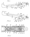
- Figs. 1 and 2 of the drawings 1 is a bushing mounted on the top of a support pillar -2 forming part of the frame, and to which a forward directed web plate 3 is secured carrying at its foremost end a transverse bearing tube 4 with a through-going shaft 5 associated with the seat frame 6 of the chair.
- This seat frame can consequently tip or tilt about a transverse axis near the front edge 7 of the seat frame.
- the seat frame comprises, in addition, two side rails of which only one is visible in the drawings and which at their rearmost end are provided with fittings 8 for a chair back, not illustrated.
- Said spring device being at the one end connected with the seat frame 6 in a hinge 10 and being at its other end connected with a first arm of a two-armed lever 12 through a damper mechanism 11 that will be more specifically explained in the following.
- Said lever 12 is pivotally mounted on the frame 6 by means of a pin 13, and its second arm carries a pin 14 that engages an inclined elongate aperture 15 in the web plate 3.
- the housing 9 of the pneumatic spring device is extended by a cylindrical bushing 16 inserted into an interior recess in the housing and secured by means of a pair of locking rings 17 so as to actually form part of the housing 9 but, nevertheless, being separable therefrom.
- the bushing 16 extends telescopically into a closed cylinder member 18 and comprises a firmly secured end wall 19 that defines a pressure fluid chamber 20 at the bottom of the cylinder member.
- a second chamber 21 is defined between the end wall 19 and a plunger 22 that fits tightly with the bushing 16, said plunger being urged towards the end wall by means of a disc spring 23 supported at its opposite side by an abutment 24 fixedly secured in the bushing.
- the two chambers 20 and 21 communicate with each other through a narrow throttle passage 25 as well as through a wider channel 26 comprising a non-return valve 27 that opens in the direction towards the chamber 20.
- the bushing 16 together with the end wall 19 will be moved inwards into the cylinder member 18, but this movement is strongly impeded by the pressure fluid in chamber 20, because it can only slowly escape through the throttle passage 25 to the chamber 21 in which the plunger 22 is pressed backwards against the effect of the spring 23.
- the passage 25 may be adapted so that the maximum movement causing the end wall 19 to abut the bottom of the cylinder member 18 takes 5 to 10 minutes. If the loading on the seat ceases or is considerably lightened during this period the frame 6 will quickly return to its basic position because the spring urged plunger 22 presses the pressure fluid back from the chamber 21 to the chamber 20, viz. through the channel 26 and the non-return valve 27.
- the said period may be extended or shortened according to desire by adjustment of the throttle passage 25.
- an adjusting screw 28 is mounted at the abutment 24, said screw being capable of longitudinally adjusting a needle 30 in the passage 25 through an axial mandrel 29 passing through the spring 23 and the plunger 22.
Landscapes
- Seats For Vehicles (AREA)
- Chairs Characterized By Structure (AREA)
Applications Claiming Priority (2)
| Application Number | Priority Date | Filing Date | Title |
|---|---|---|---|
| DK531379A DK531379A (da) | 1979-12-13 | 1979-12-13 | Stol |
| DK5313/79 | 1979-12-13 |
Publications (2)
| Publication Number | Publication Date |
|---|---|
| EP0030806A2 true EP0030806A2 (fr) | 1981-06-24 |
| EP0030806A3 EP0030806A3 (fr) | 1981-12-23 |
Family
ID=8141421
Family Applications (1)
| Application Number | Title | Priority Date | Filing Date |
|---|---|---|---|
| EP80304292A Withdrawn EP0030806A3 (fr) | 1979-12-13 | 1980-11-28 | Chaise avec mécanisme de siège réglable |
Country Status (2)
| Country | Link |
|---|---|
| EP (1) | EP0030806A3 (fr) |
| DK (1) | DK531379A (fr) |
Cited By (5)
| Publication number | Priority date | Publication date | Assignee | Title |
|---|---|---|---|---|
| EP0164267A3 (fr) * | 1984-06-08 | 1988-01-27 | Hauserman Inc. | Fauteuil inclinable |
| WO1990012220A1 (fr) * | 1989-04-05 | 1990-10-18 | Tooling Promotion Ab | Dipositif hydraulique pour chaises |
| EP0906738A3 (fr) * | 1997-10-02 | 2000-04-26 | Rolf Benz AG | Meuble d'assise, notamment chaise |
| US6402244B1 (en) * | 1999-04-13 | 2002-06-11 | Aida Development Gmbh | Aircraft passenger seat |
| CN113475886A (zh) * | 2021-08-25 | 2021-10-08 | 南通市久正人体工学股份有限公司 | 一种座椅前倾气弹簧安装结构及气弹簧的选型方法 |
Family Cites Families (1)
| Publication number | Priority date | Publication date | Assignee | Title |
|---|---|---|---|---|
| DE1226439B (de) * | 1964-08-28 | 1966-10-06 | Fritzmeier Rupert | Sitzabfederung, insbesondere fuer nicht schienengebundene Fahrzeuge |
-
1979
- 1979-12-13 DK DK531379A patent/DK531379A/da unknown
-
1980
- 1980-11-28 EP EP80304292A patent/EP0030806A3/fr not_active Withdrawn
Cited By (5)
| Publication number | Priority date | Publication date | Assignee | Title |
|---|---|---|---|---|
| EP0164267A3 (fr) * | 1984-06-08 | 1988-01-27 | Hauserman Inc. | Fauteuil inclinable |
| WO1990012220A1 (fr) * | 1989-04-05 | 1990-10-18 | Tooling Promotion Ab | Dipositif hydraulique pour chaises |
| EP0906738A3 (fr) * | 1997-10-02 | 2000-04-26 | Rolf Benz AG | Meuble d'assise, notamment chaise |
| US6402244B1 (en) * | 1999-04-13 | 2002-06-11 | Aida Development Gmbh | Aircraft passenger seat |
| CN113475886A (zh) * | 2021-08-25 | 2021-10-08 | 南通市久正人体工学股份有限公司 | 一种座椅前倾气弹簧安装结构及气弹簧的选型方法 |
Also Published As
| Publication number | Publication date |
|---|---|
| DK531379A (da) | 1981-06-14 |
| EP0030806A3 (fr) | 1981-12-23 |
Similar Documents
| Publication | Publication Date | Title |
|---|---|---|
| CA1098021A (fr) | Traduction non-disponible | |
| US5080318A (en) | Tilting control assembly for chair | |
| JPS5949802B2 (ja) | 人間工学的椅子 | |
| US10835041B2 (en) | Chair arm assembly | |
| US5425566A (en) | Working chair | |
| CA2260728C (fr) | Mecanisme de fauteuil | |
| US3837704A (en) | Seating furniture | |
| US4962962A (en) | Piece of seating furniture | |
| US4004836A (en) | Chair with tiltable spring biased back-rest | |
| US7887132B2 (en) | Chair | |
| US5160184A (en) | Controller for seating and the like | |
| US6431649B1 (en) | Working chair with synchronous seat and back adjustment | |
| US4685730A (en) | Seat, especially work seat, with several positions | |
| US5464274A (en) | Chair seat tilt adjustment and locking mechanism | |
| US5547252A (en) | Office chair | |
| US6585320B2 (en) | Tilt control mechanism for a tilt back chair | |
| US5267777A (en) | Resilient chair support | |
| US7914078B2 (en) | Adjustable lower seat for use with a stand and lean type backrest | |
| US2579502A (en) | Reclining article of furniture | |
| US9706845B2 (en) | Chair assembly | |
| US20050140183A1 (en) | Reclining chair with foot and leg rest | |
| EP0164267A2 (fr) | Fauteuil inclinable | |
| AU711396B2 (en) | Device for adjusting the inclination of the back-rest relative to the seating portion in chairs in general | |
| US5388889A (en) | Torque control mechanism for chairs | |
| US4718725A (en) | Support-and adjusting device for seat and backrest on a work chair |
Legal Events
| Date | Code | Title | Description |
|---|---|---|---|
| PUAI | Public reference made under article 153(3) epc to a published international application that has entered the european phase |
Free format text: ORIGINAL CODE: 0009012 |
|
| AK | Designated contracting states |
Designated state(s): AT BE CH DE FR GB IT LU NL SE |
|
| PUAL | Search report despatched |
Free format text: ORIGINAL CODE: 0009013 |
|
| AK | Designated contracting states |
Designated state(s): AT BE CH DE FR GB IT LU NL SE |
|
| STAA | Information on the status of an ep patent application or granted ep patent |
Free format text: STATUS: THE APPLICATION IS DEEMED TO BE WITHDRAWN |
|
| 18D | Application deemed to be withdrawn |
Effective date: 19821203 |
|
| RIN1 | Information on inventor provided before grant (corrected) |
Inventor name: JENSEN, JACOB |