EP0030894B1 - Elément résistant chauffant découpé pour radiateur électrique domestique, procédé de fabrication et radiateur s'y rapportant - Google Patents
Elément résistant chauffant découpé pour radiateur électrique domestique, procédé de fabrication et radiateur s'y rapportant Download PDFInfo
- Publication number
- EP0030894B1 EP0030894B1 EP19800401776 EP80401776A EP0030894B1 EP 0030894 B1 EP0030894 B1 EP 0030894B1 EP 19800401776 EP19800401776 EP 19800401776 EP 80401776 A EP80401776 A EP 80401776A EP 0030894 B1 EP0030894 B1 EP 0030894B1
- Authority
- EP
- European Patent Office
- Prior art keywords
- blade
- edges
- accordance
- series
- strip
- Prior art date
- Legal status (The legal status is an assumption and is not a legal conclusion. Google has not performed a legal analysis and makes no representation as to the accuracy of the status listed.)
- Expired
Links
Images

Classifications
-
- F—MECHANICAL ENGINEERING; LIGHTING; HEATING; WEAPONS; BLASTING
- F24—HEATING; RANGES; VENTILATING
- F24H—FLUID HEATERS, e.g. WATER OR AIR HEATERS, HAVING HEAT-GENERATING MEANS, e.g. HEAT PUMPS, IN GENERAL
- F24H9/00—Details
- F24H9/18—Arrangement or mounting of grates or heating means
- F24H9/1854—Arrangement or mounting of grates or heating means for air heaters
- F24H9/1863—Arrangement or mounting of electric heating means
-
- H—ELECTRICITY
- H05—ELECTRIC TECHNIQUES NOT OTHERWISE PROVIDED FOR
- H05B—ELECTRIC HEATING; ELECTRIC LIGHT SOURCES NOT OTHERWISE PROVIDED FOR; CIRCUIT ARRANGEMENTS FOR ELECTRIC LIGHT SOURCES, IN GENERAL
- H05B3/00—Ohmic-resistance heating
- H05B3/10—Heating elements characterised by the composition or nature of the materials or by the arrangement of the conductor
-
- H—ELECTRICITY
- H05—ELECTRIC TECHNIQUES NOT OTHERWISE PROVIDED FOR
- H05B—ELECTRIC HEATING; ELECTRIC LIGHT SOURCES NOT OTHERWISE PROVIDED FOR; CIRCUIT ARRANGEMENTS FOR ELECTRIC LIGHT SOURCES, IN GENERAL
- H05B3/00—Ohmic-resistance heating
- H05B3/20—Heating elements having extended surface area substantially in a two-dimensional [2D] plane, e.g. plate-heater
- H05B3/22—Heating elements having extended surface area substantially in a two-dimensional [2D] plane, e.g. plate-heater non-flexible
- H05B3/24—Heating elements having extended surface area substantially in a two-dimensional [2D] plane, e.g. plate-heater non-flexible heating conductor being self-supporting
Definitions
- the present invention relates to a cut resistant heating element, in particular for a domestic electric heater.
- It also relates, by way of application, to a radiator provided with a tel element.
- Resistant elements of the type referred to here are obtained from a metal strip a few tenths of a millimeter thick, intended to dissipate approximately 3 w / cm 2 , such as those described in patent application FR-A-2 137 068
- this ribbon two series of slots are made, nested one between the other, the slots of each series being offset on either side of the longitudinal axis of the ribbon.
- An electrical circuit is thus obtained composed of conductive metal strips left between the slots and arranged in a zigzag.
- the element thus obtained of very small thickness, has no mechanical strength, and it is necessary to fix on its edges strips of insulating material which give it a certain rigidity allowing its manipulation and its fixing in a radiator.
- the ribbon In order to radiate effectively, the ribbon is mounted vertically in the operating position. If the lower insulating strip generally behaves properly at the operating temperature, the same is not true of the upper strip which is brought to a markedly higher temperature, due in particular to the natural convection which occurs on along the ribbon.
- the tape can also be bent, the insulating strips being at the same level.
- Such a construction known from the patent specification FR-A-799 638, has the same defect as the previous one.
- the present invention aims to provide a resistant heating element such that the insulating strips are preserved from dangerous temperatures for their maintenance.
- a resistant heating element in particular for a domestic electric radiator, comprising a metal strip in which two series of nested transverse slots are made and offset respectively on either side of the longitudinal axis of the strip, the slots of each series being extended to the corresponding edge of the ribbon to constitute, by the metal strips located between the slots, an electric zig-zag conductor and the ribbon being bent along its length between its two edges arranged opposite the one from the other and substantially parallel to each other, is characterized in that, in the curved part of the ribbon, the conductive strips are folded inwards and others outwards from said part curved according to a predetermined alternation law.
- the curved part is thus split into two layers crossed successively by the air
- the metal strips have a variable section between the edges of the ribbon, so as to locate the heating part in the region of smallest section.
- the strip has, on its edges, a series of holes for receiving pins for fixing an insulating strip, and these pins are provided at their base with a shoulder to maintain the strip away from the ribbon.
- the ascending air thus passes between the ribbon and the strip to effect effective ventilation which avoids overheating the strip.
- the strip has, on its edges, a series of slots for receiving bars secured to an insulating strip.
- the domestic electric radiator comprises at least one resistant heating element in accordance with that described above and it is characterized in that it comprises supports provided with flexible claws for co-operating with ribs of the strip insulation bordering the heating element, thus allowing the fixing of the heating elements by snap-fastening.
- the heating element comprises a metallic strip 1 in which two series of slots, 2 and 3 respectively are formed, such that the slots 2 reach an edge 4 of the strip and that the slots 3, nested in the slots 2, reach the other edge 5 of the ribbon.
- the metal strips 7, 8 which remain between the slots thus constitute a zigzag electrical circuit.
- the ribbon is bent in a U along its length so that the aforementioned metal strips constitute two plies 9, 11 extending parallel to each other, on either side of the bending region 12.
- the bands 7 are folded in V towards the inside of the curved part, while the bands 8, which alternate with the bands 7, are folded in V towards the outside (fig. 1 to 4 ).
- the strips 7, 8 are folded longitudinally to form metal references 13 (fig. 8). In the bending region 12, these references are removed to reduce the section of the strips, locate the heating there and allow bending.
- claws 14 are cut from the tape and folded over an insulating strip 15. On the right side of FIG. 5, claws 14 are shown before their folding down.
- punctures 16 are formed in the edges of the ribbon, between the claws 14, and directed towards the side where the band 15 is applied, so as to become embedded in the latter and to prevent it from sliding in the claws. 14.
- Holes 17 are made in the edges 4 and 5 of the ribbon to allow it to advance in the cutting and forming machine.
- the shearing along line 6 is deliberately incomplete and leaves a band 18 which short-circuits some of the bands 7 and 8 near the end of the ribbon.
- the length of this strip 18, and therefore the number of short-circuited strips 7, 8, is determined so that the heating element has a predetermined electrical resistance, independently of accidental variations in the thickness of the metal.
- an electrical connection terminal 19 is welded to one end of the strip.
- an electric heater intended to receive the heating element which has just been described comprises a support 21 made of relatively flexible insulating material.
- the support comprises two lips 22, 23 provided with respective stiffeners 24, 25.
- the space between these lips is provided to receive an edge of the tape provided with its insulating strip 15.
- the lip 22 has a claw 26 which engages between two ribs 27 of the strip 15. To allow this engagement, the lip 22 is made flexible by an interruption 28 of the stiffener 24.
- the heating element As described, one starts with a metal ribbon in which the lateral holes 17 are made with excellent precision, because they must serve as guides for the progression of the ribbon in the cutting and forming machine.
- the insulating strips 15 are then put in place and the claws are folded down 14. Finally, the edges of the ribbon are sheared along the cutting lines 6, possibly leaving a certain length 18 unsheared. The ribbon then has the appearance shown in the left part of FIG. 5.
- the central part of the ribbon is then folded to obtain the heating element as described with reference to FIGS. 1 to 4.
- the element is then mounted in a radiator by simply snapping the edges into the supports 21 provided for this purpose (fig. 9).
- the heating element is placed as shown in fig. 1 to 4, that is to say the insulating strips at the bottom and the curved part at the top. All of the metal heats up and creates rising convection currents, which has the effect, by ventilating the element, of cooling the base, that is to say in particular the insulating strips 15 which are thus preserved.
- the ascending air In the bending region, the ascending air successively crosses two layers constituted respectively by the Vs of FIGS. 2 and 3.
- the spacing of two adjacent strips 7 (or 8) is two steps, which facilitates the passage of air.
- the passage is baffled, which improves, by turbulence, the heat exchange between the metal and the air.
- a series of holes is made in the edge 5 of the ribbon to receive a corresponding series of pins 131 provided on the insulating strip 115.
- Each pin has at its base a shoulder 132 on which the ribbon is supported. The tape is thus kept away from the tape and ventilation is established between them, which has the effect of lowering the temperature of the edge of the tape and of the insulating tape.
- the method of fixing the insulating strip 215 is substantially the same, by pins 231 provided with shoulders 232, but, moreover, the edge 205 of the strip has slots 233 in which bars are fitted 234 secured to the strip 215. The presence of these bars prevents deformation of the strip in parallelogram.
Landscapes
- Engineering & Computer Science (AREA)
- Physics & Mathematics (AREA)
- Thermal Sciences (AREA)
- Chemical & Material Sciences (AREA)
- Combustion & Propulsion (AREA)
- Mechanical Engineering (AREA)
- General Engineering & Computer Science (AREA)
- Surface Heating Bodies (AREA)
- Resistance Heating (AREA)
Description
- La présente invention concerne un élément résistant chauffant découpé, notamment pour radiateur électrique domestique.
- Elle concerne également, à titre d'application, un radiateur muni d'un tél élément.
- Les éléments résistants du genre visé ici sont obtenus à partir d'un ruban métallique de quelques dixièmes de millimètre d'épaisseur prévu pour dissiper environ 3 w/cm2, tels que ceux décrits dans la demande de brevet FR-A-2 137 068. Dans ce ruban on pratique deux séries de fentes imbriquées les unes entre les autres, les fentes de chaque série étant décalées de part et d'autre de l'axe longitudial du ruban. On obtient ainsi un circuit électrique composé des bandes métalliques conductrices laissées entre les fentes et disposées en zigzag.
- L'élément ainsi obtenu, de très faible épaisseur, ne présente aucune tenue mécanique, et l'on doit fixer sur ses bords des bandes en matière isolante qui lui confèrent une certaine rigidité permettant sa manipulation et sa fixation dans un radiateur.
- Afin de rayonner efficacement, le ruban est monté verticalement en position de fonctionnement. Si la bande isolante inférieure se comporte en général convenablement à la température de fonctionnement, il n'en est pas de même de la bande supérieure qui se trouve portée à une température nettement plus élevée, en raison notamment de la convection naturelle qui se produit le long du ruban.
- Le ruban peut être également cintré, les bandes isolantes étant au même niveau. Une telle construction, connue du fascicule de brevet FR-A-799 638, présente le même défant que la précédente.
- La présente invention vise à réaliser un élément résistant chauffant tel que les bandes isolantes soient préservées des températures dangereuses pour leurtenue.
- Suivant l'invention, un élément résistant chauffant, notament pour radiateur électrique domestique, comprenant un ruban métallique dans lequel sont pratiquées deux séries de fentes transversales imbriquées et décalées respectivement de part et d'autre de l'axe longitudinal du ruban, les fentes de chaque série étant prolongées jusqu'au bord correspondant du ruban pour constituer, par les bandes métalliques situées entre les fentes, un conducteur électrique en zig-zag et le ruban étant cintré suivant sa longueur entre ses deux bords disposés vis-à-vis l'un de l'autre et sensiblement parallèles l'un à l'autre, est caractérisé en ce que, dans la partie cintrée du ruban, les bandes conductrices sont pliées les unes vers l'intérieur et les autres vers l'extérieur de ladite partie cintrée suivant une loi d'alternance prédéterminée.
- La partie cintrée est ainsi dédoublée en deux nappes traversées successivement par l'air
- ascendant, à travers des ouvertures relativement larges disposées en chicane, ce qui assure une excellente convection.
- Suivant une réalisation préférée de l'invention, les bandes métalliques présentent une section variable entre les bords du ruban, de manière à localiser la partie chauffante dans la région de plus faible section.
- Suivant un certain mode de réalisation de l'invention, le ruban comporte, sur ses bords, une série de trous pour recevoir des picots de fixation d'une bande isolante, et ces picots sont munis à leur base d'un épaulement pour maintenir la bande éloignée du ruban.
- L'air ascendant passe ainsi entre le ruban et la bande pour effectuer une ventilation efficace qui évite de surchauffer la bande.
- Suivant un autre mode de réalisation de l'invention, le ruban comporte, sur ses bords, une série de fentes pour recevoir des barrettes solidaires d'une bande isolante.
- Cette solidarisation supplémentaire permet d'éviter une déformation du ruban en parallélogramme qui peut se produire en cas de fixation de la bande par picots.
- Suivant un autre aspect rie l'invention, le radiateur électrique domestique comprend au moins un élément résistant chauffant conforme à celui décrit plus haut et il est caractérisé en ce qu'il comprend des supports munis de griffes souples pour coppérer avec des nervures de la bande isolante bordant l'élément chaiffant, permettant ainsi la fixation des éléments chauffants par encliquetage.
- D'autres particularités et avantages de l'invention ressortiront encore de la description détaillée qui va suivre.
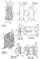
- La fig. 1 est une vue de côté d'un tronçon d'élément chauffant conforme à l'invention.
- La fig. 2 est une vue en coupe suivant II-II de la fig. 1,
- La fig. 3 est une vue en coupe suivant III-III de la fig. 1,
- La fig. 4 est une vue en perspective du tronçon de la fig. 1,
- La fig. 5 est une vue en plan du ruban avant cintrage,
- La fig. 6 est une vue en coupe suivant VI-VI de la fig. 4,
- La fig. 7 est une vue en coupe suivant VII-VII de la fig. 4,
- La fig. 8 est une vue en coupe suivant VIII-VIII de la fig. 4,
- La fig. 9 est une vue en coupe du bord du ruban fixé dans un support appartenant au radiateur,
- La fig. 10 est une vue en coupe du bord du ruban dans une variante de réalisation de l'invention,
- La fig. 11 est une vue suivant XI-XI de la fig. 9,
- La fig. 12 est une vue en coupe du bord du ruban dans une autre variante de réalisation de l'invention,
- La fig. 13 est une vue suivant XIII-XIII de la fig. 12.
- En référence aux fig. 1 à 8, l'élément chauffant comprend un ruban métallique 1 dans lequel sont pratiquées deux séries de fentes, respectivement 2 et 3, telles que les fentes 2 atteignent un bord 4 du ruban et que les fentes 3, imbriquées dans les fentes 2, atteignent l'autre bord 5 du ruban.
- Sur la partie droite de la fig. 5, aucune des fentes 2 n'atteint le bord 4, car la représentation dans cette partie de la figure correspond à une étape intermédiaire de fabrication. Pour achever la fabrication, on cisaille le bord suivant une ligne de coupe 6 qui atteint les fentes (partie gauche de la fig. 5).
- Les bandes métalliques 7, 8 qui subsistent entre les fentes constituent ainsi un circuit électrique en zigzag.
- Le ruban est cintré en U suivant sa longueur de manière que les bandes métalliques précitées constituent deux nappes 9, 11 s'étendant parallèlement l'une à l'autre, de part et d'autre de la région de cintrage 12.
- Dans la région de cintrage 12, les bandes 7 sont pliées en V vers l'intérieur de la partie cintrée, tandis que les bandes 8, qui alternent avec les bandes 7, sont pliées en V vers l'extérieur (fig. 1 à 4).
- Dans les parties latérales 9 et 11, les bandes 7, 8 sont pliées longitudinalement pour former des renvois de métal 13 (fig. 8). Dans la région de cintrage 12, ces renvois sont supprimés pour diminuer la section des bandes, y localiser le chauffage et permettre le cintrage.
- Sur les bords 4 et 5, des griffes 14 sont découpées dans le ruban et rabattues sur une bande isolante 15. Sur la partie droite de la fig. 5, des griffes 14 sont représentées avant leur rabattement.
- En outre, des crevés 16 sont pratiqués dans les bords du ruban, entre les griffes 14, et dirigés du côté où est appliquée la bande 15, de manière à venir s'incruster dans cette dernière et à l'empêcher de coulisser dans les griffes 14.
- Des trous 17 sont pratiqués dans les bords 4 et 5 du ruban pour permettre de le faire progresser dans la machine de découpage et de formage.
- Dans la partie gauche de la fig. 5, le cisaillage suivant la ligne 6 est volontairement incomplet et laisse subsister une bande 18 qui court-circuite certaines des bandes 7 et 8 voisines de l'extrêmité du ruban. La longueur de cette bande 18, et donc le nombre de bandes 7, 8 court-circuitées, est déterminée de manière que l'élément chauffant présente une résistance électrique prédéterminée, indépendamment de variations accidentelles de l'épaisseur du métal.
- Enfin, une cosse de connexion électrique 19 est soudée à une extrémité du ruban.
- En référence à la fig. 9, un radiateur électrique destiné à recevoir l'élément chauffant qui vient d'être décrit comporte un support 21 en matériau isolant relativement souple.
- Le support comprend deux lèvres 22, 23 munies de raidisseurs respectifs 24, 25. L'espace entre ces lèvres est prévu pour recevoir un bord du ruban muni de sa bande isolante 15. La lèvre 22 présente une griffe 26 qui s'engage entre deux nervures 27 de la bande 15. Pour permettre cet engagement, la lèvre 22 est rendue souple par une interruption 28 du raidisseur 24.
- Pour fabriquer l'élément chauffant tel que décrit, on part d'un ruban métallique dans lequel les trous latéraux 17 sont pratiqués avec une excellente précision, car ils doivent servir de guides à la progression du ruban dans la machine de découpe et de formage.
- Dans cette machine sont pratiquées les fentes 2 et 3 avec les renvois de métal 13, ainsi que les griffes 14 et les crevés 16. Au sortir de la machine, le ruban se présente sensiblement sous l'aspect représenté dans la partie droite de la fig. 5.
- On met ensuite en place les bandes isolantes 15 et l'on rabat les griffes 14. Enfin, on cisaille les bords du ruban suivant les lignes de coupe 6, en laissant éventuellement une certaine longueur 18 non cisaillée. Le ruban présente alors l'aspect représenté dans la partie gauche de la fig. 5.
- Après avoir soudé la cosse 19, on plie ensuite la partie centrale du ruban pour obtenir l'élément chauffant tel que décrit en référence aux fig. 1 à 4.
- On monte ensuite l'élément dans un radiateur par simple encliquetage des bords dans les supports 21 prévus à cet effet (fig. 9).
- En fonctionnement, l'élément chauffant est placé comme indiqué sur les fig. 1 à 4, c'est-à-dire les bandes isolantes en bas et la partie cintrée en haut. L'ensemble du métal s'échauffe et crée des courants de convection ascendants, ce qui a pour effet, en ventilant l'élément, de refroidir la base, c'est-à-dire notamment les bandes isolantes 15 qui sont ainsi préservées.
- Dans la région du cintrage, l'air ascendant franchit successivement deux nappes constituées respectivement par les V des fig. 2 et 3. Dans chacune des deux nappes, l'écartement de deux bandes voisines 7 (ou 8) est de deux pas, ce qui facilite le passage de l'air. De surcroît, le passage est en chicane, ce qui améliore, par turbulence, l'échange de chaleur entre le métal et l'air.
- On va maintenant décrire, en référence aux fig. 10 et 11, une variante de réalisation de l'invention, concernant plus précisément le mode de fixation des bandes isolantes.
- Une série de trous est pratiquée dans le bord 5 du ruban pour recevoir une série correspondante de picots 131 prévus sur la bande isolante 115. Chaque picot présente à sa base un épaulement 132 où vient s'appuyer le ruban. Le ruban est ainsi maintenu éloigné de la bande et une ventilation s'établit entre eux, ce qui a pour effet d'abaisser la température du bord du ruban et de la bande isolante.
- Suivant une autre variante de réalisation représentée aux fig. 12 et 13, le mode de fixation de la bande isolante 215 est sensiblement le même, par des picots 231 munis d'épaulements 232, mais, en outre, le bord 205 du ruban présente des fentes 233 dans lesquelles viennent s'encastrer des barrettes 234 solidaires de la bande 215. La présence de ces barrettes empêche une déformation du ruban en parallélogramme.
- Bien entendu, l'invention n'est pas limitée aux exemples décrits et l'on pourrait concevoir de nombreuses variantes de détail sans sortir de son cadre.
Claims (9)
Applications Claiming Priority (2)
| Application Number | Priority Date | Filing Date | Title |
|---|---|---|---|
| FR7930357 | 1979-12-11 | ||
| FR7930357A FR2471721A1 (fr) | 1979-12-11 | 1979-12-11 | Element resistant chauffant decoupe pour radiateur electrique domestique, procede de fabrication et radiateur s'y rapportant |
Publications (2)
| Publication Number | Publication Date |
|---|---|
| EP0030894A1 EP0030894A1 (fr) | 1981-06-24 |
| EP0030894B1 true EP0030894B1 (fr) | 1983-03-23 |
Family
ID=9232638
Family Applications (1)
| Application Number | Title | Priority Date | Filing Date |
|---|---|---|---|
| EP19800401776 Expired EP0030894B1 (fr) | 1979-12-11 | 1980-12-10 | Elément résistant chauffant découpé pour radiateur électrique domestique, procédé de fabrication et radiateur s'y rapportant |
Country Status (3)
| Country | Link |
|---|---|
| EP (1) | EP0030894B1 (fr) |
| DE (1) | DE3062471D1 (fr) |
| FR (1) | FR2471721A1 (fr) |
Families Citing this family (6)
| Publication number | Priority date | Publication date | Assignee | Title |
|---|---|---|---|---|
| US4550411A (en) * | 1983-03-30 | 1985-10-29 | Vg Instruments Group Limited | Sources used in molecular beam epitaxy |
| DE3328078A1 (de) * | 1983-08-03 | 1985-02-21 | Grote & Hartmann Gmbh & Co Kg, 5600 Wuppertal | Widerstandsheizelement |
| DE3605611A1 (de) * | 1986-02-21 | 1987-08-27 | Braun Ag | Verfahren zum herstellen eines heizkoerpers |
| FR2608883B1 (fr) * | 1986-12-19 | 1989-04-14 | Seb Sa | Element resistant chauffant decoupe pour radiateur electrique, son procede de fabrication et radiateur s'y rapportant |
| DE3706601A1 (de) * | 1987-02-28 | 1988-09-08 | Eichenauer Gmbh & Co Kg F | Heizkoerper mit maeanderfoermig gewundenem heizleiter und widerstandsdraht |
| EP0355210A1 (fr) * | 1988-08-26 | 1990-02-28 | Koninklijke Philips Electronics N.V. | Elément chauffant |
Family Cites Families (5)
| Publication number | Priority date | Publication date | Assignee | Title |
|---|---|---|---|---|
| DE650676C (de) * | 1934-08-31 | 1937-09-29 | Bbc Brown Boveri & Cie | Bandheizkoerper fuer elektrische Widerstandsoefen |
| FR799638A (fr) * | 1934-12-21 | 1936-06-16 | Dispositif pour le chauffage électrique de locaux | |
| US2129046A (en) * | 1935-07-01 | 1938-09-06 | Expanded Metal | Electrical heater and resistance |
| GB731208A (en) * | 1953-04-09 | 1955-06-01 | British Thomson Houston Co Ltd | Improvements in and relating to electric heating elements and methods of making same |
| DE1018512B (de) * | 1955-09-24 | 1957-10-31 | Siemens Ag | Zonenweise gefasste elektrische Leiter, insbesondere Widerstaende |
-
1979
- 1979-12-11 FR FR7930357A patent/FR2471721A1/fr active Granted
-
1980
- 1980-12-10 DE DE8080401776T patent/DE3062471D1/de not_active Expired
- 1980-12-10 EP EP19800401776 patent/EP0030894B1/fr not_active Expired
Also Published As
| Publication number | Publication date |
|---|---|
| DE3062471D1 (en) | 1983-04-28 |
| FR2471721B1 (fr) | 1983-04-01 |
| EP0030894A1 (fr) | 1981-06-24 |
| FR2471721A1 (fr) | 1981-06-19 |
Similar Documents
| Publication | Publication Date | Title |
|---|---|---|
| EP0597941B1 (fr) | Appareil electrique de cuisson et son procede de fabrication | |
| CA2222468C (fr) | Elements resistifs pour le chauffage d'un profil aerodynamique, et dispositif de chauffage d'un profil aerodynamique incorporant de tels elements | |
| DE2745689B2 (de) | Elektrisch beheizter Gasbehälter und Verfahren zu seiner Herstellung | |
| FR2613884A1 (fr) | Machine electrique comprenant un paquet de toles supportant un enroulement, et procede pour sa fabrication | |
| FR2701554A1 (fr) | Echangeur de chaleur pour composants électroniques et appareillages électro-techniques. | |
| EP0030894A1 (fr) | Elément résistant chauffant découpé pour radiateur électrique domestique, procédé de fabrication et radiateur s'y rapportant | |
| EP2776182B1 (fr) | Procede de fabrication d'un echangeur de chaleur | |
| CA1137533A (fr) | Rotor de machine electrique refroidi par circulation de gaz | |
| WO2014154786A1 (fr) | Conducteur leger auto deglacant | |
| WO2021116580A1 (fr) | Dispositif chauffant électrique pour véhicule automobile | |
| EP3113576B1 (fr) | Plateau pour la cuisson d'aliments et procédé de fabrication d'un plateau | |
| EP0214627B1 (fr) | Module de raccordement électrique | |
| FR2674720A1 (fr) | Vitrage feuillete chauffant. | |
| EP3364122B1 (fr) | Dispositif de chauffage électrique domestique, en particulier du type sèche-serviettes | |
| US2129046A (en) | Electrical heater and resistance | |
| EP1449470B1 (fr) | Elément chauffant et grille-pain électrique à isolation thermique | |
| EP0380417B1 (fr) | Connecteur électrique pour élément chauffant | |
| EP2146170B1 (fr) | Élément de radiateur et bloc pour radiateur | |
| FR2608883A1 (fr) | Element resistant chauffant decoupe pour radiateur electrique, son procede de fabrication et radiateur s'y rapportant | |
| WO2002084196A1 (fr) | Faisceau d'echangeur de chaleur comportant une surface d'echange perfectionnee | |
| EP0522960B1 (fr) | Appareil de cuisson à résistance électrique de chauffage | |
| US3283128A (en) | Electric toaster heating unit | |
| FR2489684A1 (fr) | Grille-pain electrique | |
| EP1369073B1 (fr) | Chariot porte pain perfectionné pour grille-pain | |
| FR2642636A1 (fr) | Grille en tole decoupee pour grille-pain |
Legal Events
| Date | Code | Title | Description |
|---|---|---|---|
| PUAI | Public reference made under article 153(3) epc to a published international application that has entered the european phase |
Free format text: ORIGINAL CODE: 0009012 |
|
| 17P | Request for examination filed |
Effective date: 19801215 |
|
| AK | Designated contracting states |
Designated state(s): BE DE GB IT NL |
|
| ITCL | It: translation for ep claims filed |
Representative=s name: BARZANO' E ZANARDO ROMA S.P.A. |
|
| DET | De: translation of patent claims | ||
| ITF | It: translation for a ep patent filed | ||
| GRAA | (expected) grant |
Free format text: ORIGINAL CODE: 0009210 |
|
| AK | Designated contracting states |
Designated state(s): BE DE GB IT NL |
|
| REF | Corresponds to: |
Ref document number: 3062471 Country of ref document: DE Date of ref document: 19830428 |
|
| PGFP | Annual fee paid to national office [announced via postgrant information from national office to epo] |
Ref country code: DE Payment date: 19841207 Year of fee payment: 5 |
|
| PGFP | Annual fee paid to national office [announced via postgrant information from national office to epo] |
Ref country code: NL Payment date: 19871231 Year of fee payment: 8 |
|
| PGFP | Annual fee paid to national office [announced via postgrant information from national office to epo] |
Ref country code: BE Payment date: 19890110 Year of fee payment: 9 |
|
| PG25 | Lapsed in a contracting state [announced via postgrant information from national office to epo] |
Ref country code: GB Effective date: 19891210 |
|
| PG25 | Lapsed in a contracting state [announced via postgrant information from national office to epo] |
Ref country code: BE Effective date: 19891231 |
|
| BERE | Be: lapsed |
Owner name: SEB S.A. FRANCAISE Effective date: 19891231 |
|
| PG25 | Lapsed in a contracting state [announced via postgrant information from national office to epo] |
Ref country code: NL Effective date: 19900701 |
|
| GBPC | Gb: european patent ceased through non-payment of renewal fee | ||
| NLV4 | Nl: lapsed or anulled due to non-payment of the annual fee | ||
| PG25 | Lapsed in a contracting state [announced via postgrant information from national office to epo] |
Ref country code: DE Effective date: 19900901 |
|
| PLBE | No opposition filed within time limit |
Free format text: ORIGINAL CODE: 0009261 |
|
| STAA | Information on the status of an ep patent application or granted ep patent |
Free format text: STATUS: NO OPPOSITION FILED WITHIN TIME LIMIT |