EP0031048A1 - Dispositif et procédé pour le stockage d'éléments combustibles irradiés - Google Patents
Dispositif et procédé pour le stockage d'éléments combustibles irradiés Download PDFInfo
- Publication number
- EP0031048A1 EP0031048A1 EP80107437A EP80107437A EP0031048A1 EP 0031048 A1 EP0031048 A1 EP 0031048A1 EP 80107437 A EP80107437 A EP 80107437A EP 80107437 A EP80107437 A EP 80107437A EP 0031048 A1 EP0031048 A1 EP 0031048A1
- Authority
- EP
- European Patent Office
- Prior art keywords
- leakage detection
- detection space
- measuring device
- container
- measuring
- Prior art date
- Legal status (The legal status is an assumption and is not a legal conclusion. Google has not performed a legal analysis and makes no representation as to the accuracy of the status listed.)
- Withdrawn
Links
- 239000002915 spent fuel radioactive waste Substances 0.000 title claims abstract description 7
- 238000000034 method Methods 0.000 title claims description 11
- 239000007789 gas Substances 0.000 claims abstract description 51
- 238000001514 detection method Methods 0.000 claims abstract description 38
- 239000001307 helium Substances 0.000 claims abstract description 9
- 229910052734 helium Inorganic materials 0.000 claims abstract description 9
- SWQJXJOGLNCZEY-UHFFFAOYSA-N helium atom Chemical compound [He] SWQJXJOGLNCZEY-UHFFFAOYSA-N 0.000 claims abstract description 9
- 239000000446 fuel Substances 0.000 claims abstract description 7
- 238000003860 storage Methods 0.000 claims abstract description 5
- 230000000712 assembly Effects 0.000 claims abstract 2
- 238000000429 assembly Methods 0.000 claims abstract 2
- 238000012544 monitoring process Methods 0.000 claims description 5
- 230000008878 coupling Effects 0.000 claims description 3
- 238000010168 coupling process Methods 0.000 claims description 3
- 238000005859 coupling reaction Methods 0.000 claims description 3
- 230000000694 effects Effects 0.000 claims description 3
- 238000011144 upstream manufacturing Methods 0.000 claims description 2
- 238000005259 measurement Methods 0.000 description 12
- 230000036316 preload Effects 0.000 description 2
- 238000005070 sampling Methods 0.000 description 2
- XLYOFNOQVPJJNP-UHFFFAOYSA-N water Substances O XLYOFNOQVPJJNP-UHFFFAOYSA-N 0.000 description 2
- 238000004458 analytical method Methods 0.000 description 1
- 238000009530 blood pressure measurement Methods 0.000 description 1
- 238000001816 cooling Methods 0.000 description 1
- 238000013461 design Methods 0.000 description 1
- 238000011156 evaluation Methods 0.000 description 1
- 238000007689 inspection Methods 0.000 description 1
- 238000012432 intermediate storage Methods 0.000 description 1
- 230000007774 longterm Effects 0.000 description 1
- 238000004949 mass spectrometry Methods 0.000 description 1
- 238000012986 modification Methods 0.000 description 1
- 230000004048 modification Effects 0.000 description 1
- 230000000149 penetrating effect Effects 0.000 description 1
- 238000005086 pumping Methods 0.000 description 1
- 230000005855 radiation Effects 0.000 description 1
- 238000007789 sealing Methods 0.000 description 1
- 230000035945 sensitivity Effects 0.000 description 1
Images
Classifications
-
- G—PHYSICS
- G21—NUCLEAR PHYSICS; NUCLEAR ENGINEERING
- G21F—PROTECTION AGAINST X-RADIATION, GAMMA RADIATION, CORPUSCULAR RADIATION OR PARTICLE BOMBARDMENT; TREATING RADIOACTIVELY CONTAMINATED MATERIAL; DECONTAMINATION ARRANGEMENTS THEREFOR
- G21F5/00—Transportable or portable shielded containers
- G21F5/005—Containers for solid radioactive wastes, e.g. for ultimate disposal
- G21F5/008—Containers for fuel elements
Definitions
- the invention relates to a device and a method for storing spent fuel elements of a nuclear reactor using a fuel transport container with a cavity for receiving at least one fuel element and a lid for gas-tight closure of an opening leading into the cavity.
- a fuel transport container with a cavity for receiving at least one fuel element and a lid for gas-tight closure of an opening leading into the cavity.
- the gas-tight closure remains reliably effective even in the case of long-term storage, which takes, for example, several years, because otherwise radioactivity could be discharged.
- the latter must be avoided, in particular if the residual heat still emanating from the spent fuel elements is dissipated to the atmosphere via air cooling. Therefore, the invention is looking for a way to easily and reliably monitor the tightness.
- the device according to the invention is designed such that the cavity is provided with a trace gas that a leakage detection space covering the cross section of the opening is created with an additional cover and that the leakage detection space is connected to a measuring device for the trace gas for monitoring the gas-tight seal. Since the trace gas can only enter the leakage detection space via leaks, the invention makes it possible to reliably detect leaks. This results in a permanent monitoring of the function of the sealing of the transport container when the connection to the measuring device is constantly open. But even a connection that is only temporary, for example periodically, allows the leaky transport container to be separated out and / or the leakage gases to be removed in a controlled manner.
- Helium is particularly suitable as a trace gas because it is present in the air with such small proportions that even the smallest additional proportions that escape through leaks lead to a significant increase in concentration and can be determined with certainty.
- the invention can also be implemented with other trace gases.
- the leakage detection space which is preferably a recess in the additional cover, can be connected to a measuring device for one transport container each.
- a measuring device for one transport container each.
- several transport containers with their respective leakage detection spaces will advantageously be connected to a common measuring device via valves.
- the valves then allow individual containers to be connected to the measuring device in such a way that the tightness of each container can be provided and a possibly leaky container can be sorted out.
- the connecting lines of the transport containers with the measuring device form a grouping of the transport containers that can be connected overall to the measuring device, adapted to the spatial arrangement of the transport containers.
- the transport containers are preferably combined in rows.
- a measuring container can be connected upstream of the measuring device, the volume of which is advantageously a multiple of that of the leakage detection space. This can improve the accuracy of the measurement, because it is possible to store the sample gas in the measuring container for the period of the measurement after a relatively short transport time of the sample gas through the pipes that connect the leakage detection space to the measurement device, and thus disturbing leaks that result from the Pipe system come from, keep as far as possible.
- the measuring container can be brought to a high vacuum (eg P ⁇ 10 -1 mbar) before the measurement, so that the sample gas preload can be neglected. The influence of the gas in the pipeline can be reduced by evacuating with the vacuum pump.
- Leakage detection space and measuring device can be connected to a vacuum system with a vacuum pump with a lower pressure than in the cavity. Furthermore, the measuring device can be designed together with a vacuum pump and possibly a measuring container as a mobile system, which is connected to the transport container to be checked in each case with quick-action couplings.
- Working with the device according to the invention is advantageously such that the transport container with a trace gas is provided, that the leakage detection space assigned to the transport container is evacuated, that the pressure rise in the leakage detection space is then determined as a function of time, that the trace gas content in the leakage detection space is determined and that the transport container is sealed, extracted or removed if a limit value of the trace gas content is exceeded.
- Sucking off means a controlled, if necessary constant removal of the leakage gases.
- connecting lines between the leakage detection space and a device for determining the trace gas content can be evacuated.
- the leakage gases resulting from the invention can be stored for final storage without great effort because of their small amount. But you can also control, i.e. taking into account all radiation protection regulations etc. Filters and delay lines can be used if necessary to maintain the permissible delivery rates, which are monitored with activity measuring points.
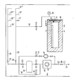
- the transport containers 2 which are also used to transport the fuel elements 1 and which each hold several, for example eight, fuel elements 1, are placed in rows in a warehouse indicated by line 3.
- the cavity is 5 the transport container 2, of which only one is shown, is closed with a cover 6 provided for transport, which is inserted into an opening 7 leading into the cavity 5 and is intended to ensure a gas-tight closure.
- a gas line accessible via a valve 8 is provided in the cover 6.
- a further cover is designated, which ends the end of the container 2 flush for transport.
- the transport container 5 Upon arrival in the warehouse 3, the transport container 5 is evacuated to, for example, 0.2 bar. Then a filling with a trace gas is introduced, which is only present in low concentrations in the surrounding atmosphere and therefore causes a noticeable increase in concentration even with small additional amounts.
- Helium is preferably used, which is filled with 10 vol.%, For example. Its concentration changes (He content in air 5 ppm) can be detected by mass spectrometry.
- a cover 10 is additionally placed on the upper end face and forms a leakage detection space 11 with a recess.
- the cover 10 covers the entire upper end face of the transport container 2, so that all leakages that can occur in the area of the opening 7 of the transport container 2 are collected with the leakage detection space 11.
- the tightness of the leakage detection space against the outside air is made as large as possible. It ensures leakage rates of a maximum of 10-2 mbar l / s.
- the leakage detection chamber 11 is connected via a pipeline 12 which is connected via a solenoid valve 13 connected to a vacuum pump 14. It is evacuated to a negative pressure P 2 of approximately 1 mbar, which is lower than the pressure P 1 in the cavity 5 and can be monitored with a pressure gauge 15 if it rises due to leakage after the valve 13 has been closed.
- the measuring device is a mass spectrometer 16, which contains a very fine vacuum pump 17 as a helium analysis device, so that the gas to be examined can be conveyed.
- trace gas concentration e.g. helium
- one of the pipeline strings 24, 25 assigned to the container rows, which each has a plurality of branch lines 12, 12 ', 12 "etc. and 26, 26', 26” etc. leading to the containers 2 , 22 and 27 or 28 including the measuring container 20 are evacuated to a pressure of approximately 1 mbar by the vacuum pump 14 or by the pump 17 of the helium analyzer 16.
- the vacuum pump 14 is equipped with sufficient pumping speed to even with a pipeline network resistance of 10 -3 - 10 -2 mbar 1 / s yet to achieve the desired final vacuum of about 1 mbar.
- the measurement gas By opening the solenoid valve 13 attached to the corresponding leakage detection space 11, the measurement gas, which is at a higher pressure level, expands in a short time via the pipeline system 12, 25 into the measurement container 20.
- the sample gas Due to the pre-evacuation, the sample gas is preloaded by residual gas in the pipes 12, 25 and in the measurement reduced gas container 20 and achieved a rapid inflow to the sample gas container 20 by the pressure level difference. This minimization of the inflow time enables the penetrating external leakage into the piping system 12, 25 to be tolerated.
- a sample gas sample in the container 20 is isolated from this sample gas stream by closing the fittings 21, 22 attached directly to the sample gas container 20.
- This container is designed with a relatively low effort in a tightness of 10- 7 mbar l / s, so that here the intrusion air falsifying the measurement can be kept away.
- the trace gas concentration increase for example helium content
- a sampling possibility is provided instead of the pipeline 12 as a mobile leakage transport system in the leakage detection space.
- One or more sample gas containers and a vacuum pump are located on a mobile unit. After being connected to the leakage detection chamber, the evacuated sample gas container serves to record the leaks, and the vacuum pump to evacuate the leakage detection chamber.
- the transport to the trace gas concentration measuring device (for example helium measurement) takes place, where by evacuation the leakage gases are transferred for the purpose of measurement and control levied delivery.
- the sampling device is designed such that the leakage gas is taken over in a short time, for example by means of quick-action couplings etc., and therefore only short inspection times are required in the radiation-endangered atmosphere of warehouse 3.
- the pipe system shown in the figure can also serve to deliver increased leakage rates from leaky containers 2 in the relatively long periods between the monitoring measurements, which are largely carried out by remote control and without the use of personnel, also by remote control.
- the outlet line 29 then leads, for example, via an activity measuring point 30 into a suitable exhaust system with filters, delay lines, chimneys, etc. not shown.
Landscapes
- Physics & Mathematics (AREA)
- Engineering & Computer Science (AREA)
- General Engineering & Computer Science (AREA)
- High Energy & Nuclear Physics (AREA)
- Examining Or Testing Airtightness (AREA)
- Monitoring And Testing Of Nuclear Reactors (AREA)
Applications Claiming Priority (2)
| Application Number | Priority Date | Filing Date | Title |
|---|---|---|---|
| DE19792950198 DE2950198A1 (de) | 1979-12-13 | 1979-12-13 | Einrichtung und verfahren zur lagerung von verbrauchten brennelementen |
| DE2950198 | 1979-12-13 |
Publications (1)
| Publication Number | Publication Date |
|---|---|
| EP0031048A1 true EP0031048A1 (fr) | 1981-07-01 |
Family
ID=6088403
Family Applications (1)
| Application Number | Title | Priority Date | Filing Date |
|---|---|---|---|
| EP80107437A Withdrawn EP0031048A1 (fr) | 1979-12-13 | 1980-11-27 | Dispositif et procédé pour le stockage d'éléments combustibles irradiés |
Country Status (4)
| Country | Link |
|---|---|
| US (1) | US4427893A (fr) |
| EP (1) | EP0031048A1 (fr) |
| JP (1) | JPS5693085A (fr) |
| DE (1) | DE2950198A1 (fr) |
Cited By (6)
| Publication number | Priority date | Publication date | Assignee | Title |
|---|---|---|---|---|
| FR2486701A1 (fr) * | 1980-07-08 | 1982-01-15 | Nuklear Service Gmbh Gns | Conteneur blinde pour le transport et le stockage de substances radioactives |
| FR2552519A1 (fr) * | 1983-09-22 | 1985-03-29 | Commissariat Energie Atomique | Dispositif d'obturation d'une enceinte de confinement |
| GB2166680A (en) * | 1984-11-13 | 1986-05-14 | Westinghouse Electric Corp | Closure system for a spent fuel storage cask |
| US4983352A (en) * | 1984-11-13 | 1991-01-08 | Westinghouse Electric Corp. | Closure system for a spent fuel storage cask |
| US5089214A (en) * | 1990-07-26 | 1992-02-18 | Westinghouse Electric Corp. | Apparatus for monitoring the pressure within a cask containing radioactive material |
| EP0978849A1 (fr) * | 1998-08-01 | 2000-02-09 | GNB Gesellschaft für Nuklear-Behälter mbH | Conteneur pour le stockage définitif d'éléments combustibles épuisés de centrales nucléaires |
Families Citing this family (7)
| Publication number | Priority date | Publication date | Assignee | Title |
|---|---|---|---|---|
| US4576274A (en) * | 1983-05-26 | 1986-03-18 | Cart-O-Matic Aktiebolag | Means for the storing of carts such as shopping carts |
| GB8402669D0 (en) * | 1984-02-01 | 1984-03-07 | English Electric Co Ltd | Storage arrangements for nuclear fuel |
| KR930003174A (ko) * | 1991-07-18 | 1993-02-24 | 데릭 제임스 맥코맥 | 핵 연료용기 |
| FR2777090B1 (fr) * | 1998-04-07 | 2000-05-05 | Commissariat Energie Atomique | Procede de msesure de l'activite tritium d'un fut de dechets radioactifs |
| JP6529401B2 (ja) * | 2015-09-16 | 2019-06-12 | 一般財団法人電力中央研究所 | 放射性物質密封容器のガス漏洩検知装置及び方法並びにプログラム |
| EP3792935B1 (fr) * | 2019-09-16 | 2021-12-01 | GNS Gesellschaft für Nuklear-Service mbH | Procédé de séchage des récipients de transport et / ou de stockage |
| CN114112226A (zh) * | 2021-12-08 | 2022-03-01 | 中国原子能科学研究院 | 乏燃料元件的破损检测装置和方法 |
Citations (1)
| Publication number | Priority date | Publication date | Assignee | Title |
|---|---|---|---|---|
| DE2854358A1 (de) * | 1977-12-16 | 1979-06-21 | Nl Industries Inc | Transportbehaelter fuer radioaktive materialien |
Family Cites Families (3)
| Publication number | Priority date | Publication date | Assignee | Title |
|---|---|---|---|---|
| US3824839A (en) | 1971-09-24 | 1974-07-23 | Varian Associates | Leak detecting system and method for passing a measured sample of gas to a leak detector |
| US3982134A (en) | 1974-03-01 | 1976-09-21 | Housholder William R | Shipping container for nuclear fuels |
| DE2905094C2 (de) | 1979-02-10 | 1982-03-18 | GNS Gesellschaft für Nuklear-Service mbH, 4300 Essen | Abschirmtransport- und/oder Abschirmlagerbehälter |
-
1979
- 1979-12-13 DE DE19792950198 patent/DE2950198A1/de not_active Ceased
-
1980
- 1980-11-27 EP EP80107437A patent/EP0031048A1/fr not_active Withdrawn
- 1980-12-10 US US06/215,136 patent/US4427893A/en not_active Expired - Lifetime
- 1980-12-12 JP JP17646280A patent/JPS5693085A/ja active Pending
Patent Citations (1)
| Publication number | Priority date | Publication date | Assignee | Title |
|---|---|---|---|---|
| DE2854358A1 (de) * | 1977-12-16 | 1979-06-21 | Nl Industries Inc | Transportbehaelter fuer radioaktive materialien |
Cited By (8)
| Publication number | Priority date | Publication date | Assignee | Title |
|---|---|---|---|---|
| FR2486701A1 (fr) * | 1980-07-08 | 1982-01-15 | Nuklear Service Gmbh Gns | Conteneur blinde pour le transport et le stockage de substances radioactives |
| FR2552519A1 (fr) * | 1983-09-22 | 1985-03-29 | Commissariat Energie Atomique | Dispositif d'obturation d'une enceinte de confinement |
| EP0147250A1 (fr) * | 1983-09-22 | 1985-07-03 | Commissariat A L'energie Atomique | Enceinte de confinement pour produits dangereux et notamment radioactifs |
| GB2166680A (en) * | 1984-11-13 | 1986-05-14 | Westinghouse Electric Corp | Closure system for a spent fuel storage cask |
| US4983352A (en) * | 1984-11-13 | 1991-01-08 | Westinghouse Electric Corp. | Closure system for a spent fuel storage cask |
| US5089214A (en) * | 1990-07-26 | 1992-02-18 | Westinghouse Electric Corp. | Apparatus for monitoring the pressure within a cask containing radioactive material |
| EP0468233A3 (en) * | 1990-07-26 | 1992-11-04 | Westinghouse Electric Corporation | Apparatus and method for monitoring the pressure within a cask containing potentially hazardous gas |
| EP0978849A1 (fr) * | 1998-08-01 | 2000-02-09 | GNB Gesellschaft für Nuklear-Behälter mbH | Conteneur pour le stockage définitif d'éléments combustibles épuisés de centrales nucléaires |
Also Published As
| Publication number | Publication date |
|---|---|
| US4427893A (en) | 1984-01-24 |
| DE2950198A1 (de) | 1981-06-19 |
| JPS5693085A (en) | 1981-07-28 |
Similar Documents
| Publication | Publication Date | Title |
|---|---|---|
| DE112014004741B4 (de) | Leckageprüfvorrichtung und leckageprüfverfahren | |
| DE3828588C1 (fr) | ||
| EP1238253B1 (fr) | Procede pour detecter et localiser des fuites, et dispositif pour mettre en oeuvre ledit procede | |
| DE3421533A1 (de) | Gegenstrom-leckdetektor mit kuehlfalle | |
| EP2994736B1 (fr) | Agencement de contrôle d'étanchéité et procédé de contrôle d'étanchéité | |
| DE2950198A1 (de) | Einrichtung und verfahren zur lagerung von verbrauchten brennelementen | |
| DE102009004363A1 (de) | Leckdetektionsverfahren | |
| DE69304677T2 (de) | Verfahren und Einrichtung zum Auffinden von Lecks der Durchführungen im Behälterdeckel eines in Betrieb befindlichen Kernreaktors | |
| DE69208108T2 (de) | Verfahren und Vorrichtung zur Prüfung von Gasleckage | |
| DE19542330A1 (de) | Anordnung zur Leckfeststellung an einem Brennelement für einen Druckwasserkernreaktor | |
| EP1119752A1 (fr) | Detecteur de fuites pelliculaire | |
| EP0598789B1 (fr) | Procede et dispositif pour le prelevement d'echantillons dans l'atmosphere d'un reservoir ferme etanche aux gaz, en particulier d'un reservoir de securite d'un reacteur d'une centrale nucleaire | |
| CN107993731A (zh) | 一种反应堆严重事故后安全壳内气体可燃性监测系统 | |
| DE2403360A1 (de) | Leckpruefverfahren | |
| DE2441124B2 (de) | Lecksucheinrichtung | |
| WO2016096499A1 (fr) | Dispositif et procédé pour réaliser un test d'étanchéité de capsules de barres de combustible | |
| EP2801808A1 (fr) | Agencement de contrôle d'étanchéité et procédé de contrôle d'étanchéité | |
| DE69308055T2 (de) | Verfahren zum Nachweis und zur globalen Quantisierung von Lecks in wenigstens einer Verbindung eines Behälters | |
| CN207052304U (zh) | 一种反应堆严重事故后安全壳内气体浓度监测系统 | |
| DE2441123A1 (de) | Verfahren zur dichtigkeitspruefung von gegenstaenden | |
| DE102013104682B3 (de) | Dichtheitsprüfanordnung und Dichtheitsprüfverfahren | |
| DE69510591T2 (de) | System zur Erkennung von schadhaften Kernbrennstäben | |
| EP0408939B1 (fr) | Procédé et dispositif pour l'échantillonnage de l'air du confinement pour un réacteur | |
| DE2846826B2 (de) | Verfahren und Einrichtung zur Bestimmung des Anteiles an nicht kondensierbaren Gasen in Dämpfen | |
| EP0049438B1 (fr) | Procédé et dispositif de stockage de récipients pour matières radioactives |
Legal Events
| Date | Code | Title | Description |
|---|---|---|---|
| PUAI | Public reference made under article 153(3) epc to a published international application that has entered the european phase |
Free format text: ORIGINAL CODE: 0009012 |
|
| AK | Designated contracting states |
Designated state(s): SE |
|
| 17P | Request for examination filed |
Effective date: 19811030 |
|
| STAA | Information on the status of an ep patent application or granted ep patent |
Free format text: STATUS: THE APPLICATION IS DEEMED TO BE WITHDRAWN |
|
| 18D | Application deemed to be withdrawn |
Effective date: 19840613 |
|
| RIN1 | Information on inventor provided before grant (corrected) |
Inventor name: QUEISER, HORST Inventor name: ECKHARDT, BERND |