EP0031131A1 - Véhicule commercial comportant une capsule placée essentiellement à l'intérieur du pourtour de la cabine pour recevoir un équipement moteur - Google Patents
Véhicule commercial comportant une capsule placée essentiellement à l'intérieur du pourtour de la cabine pour recevoir un équipement moteur Download PDFInfo
- Publication number
- EP0031131A1 EP0031131A1 EP80107953A EP80107953A EP0031131A1 EP 0031131 A1 EP0031131 A1 EP 0031131A1 EP 80107953 A EP80107953 A EP 80107953A EP 80107953 A EP80107953 A EP 80107953A EP 0031131 A1 EP0031131 A1 EP 0031131A1
- Authority
- EP
- European Patent Office
- Prior art keywords
- wall
- capsule
- commercial vehicle
- cab
- vehicle according
- Prior art date
- Legal status (The legal status is an assumption and is not a legal conclusion. Google has not performed a legal analysis and makes no representation as to the accuracy of the status listed.)
- Granted
Links
- 239000002775 capsule Substances 0.000 title claims abstract description 38
- 238000010521 absorption reaction Methods 0.000 claims abstract description 32
- 238000001816 cooling Methods 0.000 claims abstract description 21
- 239000000463 material Substances 0.000 claims abstract description 5
- 239000011358 absorbing material Substances 0.000 claims abstract description 4
- 239000006096 absorbing agent Substances 0.000 claims description 19
- 239000013013 elastic material Substances 0.000 claims description 3
- 238000002485 combustion reaction Methods 0.000 description 6
- 230000005540 biological transmission Effects 0.000 description 3
- 238000010276 construction Methods 0.000 description 3
- 238000009434 installation Methods 0.000 description 3
- 230000015572 biosynthetic process Effects 0.000 description 2
- 238000013016 damping Methods 0.000 description 2
- 230000000694 effects Effects 0.000 description 2
- XLYOFNOQVPJJNP-UHFFFAOYSA-N water Substances O XLYOFNOQVPJJNP-UHFFFAOYSA-N 0.000 description 2
- 238000009825 accumulation Methods 0.000 description 1
- 238000005253 cladding Methods 0.000 description 1
- 230000006378 damage Effects 0.000 description 1
- 230000001771 impaired effect Effects 0.000 description 1
- 239000012858 resilient material Substances 0.000 description 1
- 238000009423 ventilation Methods 0.000 description 1
Images
Classifications
-
- B—PERFORMING OPERATIONS; TRANSPORTING
- B60—VEHICLES IN GENERAL
- B60R—VEHICLES, VEHICLE FITTINGS, OR VEHICLE PARTS, NOT OTHERWISE PROVIDED FOR
- B60R13/00—Elements for body-finishing, identifying, or decorating; Arrangements or adaptations for advertising purposes
- B60R13/08—Insulating elements, e.g. for sound insulation
- B60R13/0838—Insulating elements, e.g. for sound insulation for engine compartments
-
- B—PERFORMING OPERATIONS; TRANSPORTING
- B60—VEHICLES IN GENERAL
- B60K—ARRANGEMENT OR MOUNTING OF PROPULSION UNITS OR OF TRANSMISSIONS IN VEHICLES; ARRANGEMENT OR MOUNTING OF PLURAL DIVERSE PRIME-MOVERS IN VEHICLES; AUXILIARY DRIVES FOR VEHICLES; INSTRUMENTATION OR DASHBOARDS FOR VEHICLES; ARRANGEMENTS IN CONNECTION WITH COOLING, AIR INTAKE, GAS EXHAUST OR FUEL SUPPLY OF PROPULSION UNITS IN VEHICLES
- B60K11/00—Arrangement in connection with cooling of propulsion units
- B60K11/08—Air inlets for cooling; Shutters or blinds therefor
-
- B—PERFORMING OPERATIONS; TRANSPORTING
- B60—VEHICLES IN GENERAL
- B60R—VEHICLES, VEHICLE FITTINGS, OR VEHICLE PARTS, NOT OTHERWISE PROVIDED FOR
- B60R13/00—Elements for body-finishing, identifying, or decorating; Arrangements or adaptations for advertising purposes
- B60R13/08—Insulating elements, e.g. for sound insulation
- B60R13/0884—Insulating elements, e.g. for sound insulation for mounting around noise sources, e.g. air blowers
-
- F—MECHANICAL ENGINEERING; LIGHTING; HEATING; WEAPONS; BLASTING
- F01—MACHINES OR ENGINES IN GENERAL; ENGINE PLANTS IN GENERAL; STEAM ENGINES
- F01P—COOLING OF MACHINES OR ENGINES IN GENERAL; COOLING OF INTERNAL-COMBUSTION ENGINES
- F01P11/00—Component parts, details, or accessories not provided for in, or of interest apart from, groups F01P1/00 - F01P9/00
- F01P11/12—Filtering, cooling, or silencing cooling-air
-
- F—MECHANICAL ENGINEERING; LIGHTING; HEATING; WEAPONS; BLASTING
- F01—MACHINES OR ENGINES IN GENERAL; ENGINE PLANTS IN GENERAL; STEAM ENGINES
- F01P—COOLING OF MACHINES OR ENGINES IN GENERAL; COOLING OF INTERNAL-COMBUSTION ENGINES
- F01P1/00—Air cooling
- F01P2001/005—Cooling engine rooms
Definitions
- the invention relates to a commercial vehicle with a substantially inside the outline of the cab, consisting of sound-reducing material capsule for receiving a drive unit, which has an air inlet and an air outlet on its rear, the cooling device of the inside of the air inlet Drive unit is arranged.
- a commercial vehicle of the type mentioned above is known from DE-OS 28 01 339.
- it has an air inlet opening on the front end. in which the water cooler is arranged and several e.g. behind the oil pan near the capsule bottom and on the back of the caps are outlet openings, whereby a cooling air flow directed in the longitudinal direction of the vehicle is achieved in the capsule.
- the openings in the capsule are not shielded from the outside by any further noise-damping measures and that openings in the capsule in particular are present directly at the noise source, so that e.g. the noise from the cooling fan and also from the motor can escape unhindered through the existing openings.
- the invention has for its object to improve the soundproofing lining or the capsule of the internal combustion engine consisting of noise-reducing material in a commercial vehicle of the type mentioned in such a way that its disadvantages are avoided.
- the capsule is designed as a closed housing except for the inlet and outlet opening, and that the inlet and outlet opening are each covered by an absorption section designed as an absorption channel.
- the improvement of the capsule according to the invention has the advantage that the drive motor arranged inside the capsule immediately. no sounds can reach the outside. Furthermore, it is advantageous that the absorption paths in front of the inlet and outlet openings provide an optimal reduction of the there escaping noise is achieved.
- any internal combustion engine can be installed in the capsule without any special changes and that, in addition, no additional cooling fan is required to ventilate the interior of the capsule.
- the absorption channels extend in the longitudinal direction of the vehicle.
- the rear absorption path be formed by two transverse walls which are offset with respect to one another in the longitudinal direction of the vehicle and partially overlap, the spacing of which from one another Cross section of the air outlet opening.
- this should be formed by an approximately parallel to the plane of the front wall running sound absorber shaft, the air inflow openings of which are arranged offset to the inlet opening of the capsule.
- This idea of the invention therefore relates to absorption sections running transversely to the longitudinal direction of the vehicle.
- the transverse arrangement of the front absorption section has the further advantage that the front wall of the driver's cab can simultaneously serve as part of the absorber shaft and thus the installation of a further sound-absorbing transverse wall can be saved.
- the sound absorber shaft extend in the direction of a cooling air extending as far as the cooling device channel is arranged and this forms the entire absorption path together with the sound absorber shaft.
- the wall covering the sound absorber shaft to the outside is also covered with sound-absorbing material.
- the wall delimiting the sound absorber shaft to the outside to improve passive safety is made of elastic material, and is attached to the front or an inner wall of the driver's cab via flexible struts. This gives the commercial vehicle a "soft nose" which in particular provides better protection for pedestrians.
- the outer shaft wall running as part of the front wall, in the plane thereof is designed as a dimensionally stable component and extends over the width and height of the front wall and that is also distributed over a plurality of the width of the front wall and vertical flexible struts on the front wall bw. a rigid inner wall is attached. This attachment of the shaft wall also makes it possible to provide a crumple zone in front-steering vehicles.
- the outer shaft wall has an upward-pivoting flap at the level of the inlet opening of the cooling air duct.
- the bumper is included in the running of the wall, the wall part running at the height of the bumper being reinforced and by means of a special connection elements is attached to the side members of the vehicle frame.
- the aim of the invention is to ensure that the aesthetic design of the front wall of the cab is not impaired as far as possible.
- the outer shaft wall be adapted to the shape of the front wall.
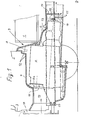
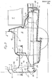
- a commercial vehicle 1, not shown in more detail, has a cab 2 in a front-link design. In the direction of travel, the cab 2 is delimited at the front by a steeply sloping front wall 3.
- a driver's cab floor 4 Within the outline of the driver's cab 2 is a driver's cab floor 4 a drive unit 5 is elastically mounted on longitudinal members 28 of a chassis frame via elastic bearing elements, not shown.
- the drive unit 5 consists of an internal combustion engine 6 and a manual transmission 7.
- the entire drive unit is housed in the interior 8 of an engine capsule 9, the walls of which are made of sound-reducing material.
- the capsule 9 forms a self-contained housing which has an air inlet opening 10 only on its front side and an air outlet opening 11 (dash-dotted line) on the rear side behind the manual transmission 7.
- the driver's cab 2 is designed to be tiltable forward in the direction of travel.
- the capsule consists of a capsule hood 12 fixed to the driver's cab and a capsule lower part 13 fastened, for example, to the longitudinal members 28 of the chassis frame. In order to prevent noises from the capsule interior and capsule lower part from passing out of the capsule interior 8, this is through a labyrinthine Seal covered.
- the absorption channels 14 and 15 running in the longitudinal direction of the vehicle take up a certain amount of space.
- the rear absorption path is offset by two in the longitudinal direction of the vehicle, perpendicular to one another and partially overlapping Transverse walls 16 and 17 are formed, the distance between the two walls 16 and 17 forming the downward outlet opening 11.
- the drive motor 6 is an air-cooled internal combustion engine with a cooling air blower 6a.
- a water-cooled internal combustion engine can also be installed as the drive motor 6, the water cooler then being able to be arranged within the inlet opening 10.
- the front absorption path located in front of the cooling device of the drive motor runs transversely to the longitudinal direction of the vehicle (as shown by dash-dotted lines) in order to save further installation space in the front area of the driver's cab.
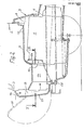
- the absorption section lying in front of the cooling fan 6a is extended by an approximately parallel to the plane of the front wall 3 to this sound absorber shaft 18, the air inlet openings 19 of the shaft above the inlet openings 10 of the capsule below the windshield of the cab.
- the absorption duct 14 is completely covered to the outside by the sound absorber shaft 18, whereby a further reduction in engine noise is achieved. It is provided that the wall 20 covering the sound absorber shaft 18 to the outside is covered with sound absorbing material.
- the absorber shaft 18 extends over the central region of the front wall 3 and projects towards the front in the direction of travel.
- the wall 20 consists of an elastic material, in particular plastic.
- a flap 21 secures the door Accessibility to the absorption channel 14 and vehicle units lying directly behind the front wall 3.
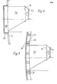
- the absorption channel 14 is also covered by a sound absorber shaft 22 running transversely to this.
- the wall 23 delimiting the shaft 22 to the outside runs within the plane of the front wall 3 and thereby replaces part or all of the front wall.
- the front bumper is drawn into the course of the wall 23, the height of the wall 23 being reinforced by cross bars 24 which are fastened to the side members 28 by means of special connecting elements 25.
- the remaining part of the wall 23 is fastened to a cab interior wall 26 by means of struts arranged essentially vertically and, as shown in FIG. 5, distributed over the width of the front wall, the struts 27 preferably being made of resilient material.
- the absorber shaft 22 is at the same time part of a crumple zone in the region of the front wall of the cab.
- the effect of the crumple zone can be further enhanced if the outer wall 23 and the inner wall 26 are designed to be dimensionally stable, so that when the wall 23 is subjected to an impact, e.g. in the event of a rear-end collision, the forces acting are distributed to all the resiliently designed struts 27, so that part of the energy is already destroyed by a change in shape before the remaining information energy is passed on to the interior wall of the cab.
- the absorption duct 14 simultaneously forms the air inlet duct for the cooling fan 6a and the absorption duct 15 the air outflow duct from the capsule 9.
Landscapes
- Engineering & Computer Science (AREA)
- Mechanical Engineering (AREA)
- Acoustics & Sound (AREA)
- Combustion & Propulsion (AREA)
- Chemical & Material Sciences (AREA)
- Physics & Mathematics (AREA)
- Transportation (AREA)
- General Engineering & Computer Science (AREA)
- Body Structure For Vehicles (AREA)
- Cooling, Air Intake And Gas Exhaust, And Fuel Tank Arrangements In Propulsion Units (AREA)
- Vehicle Interior And Exterior Ornaments, Soundproofing, And Insulation (AREA)
- Agricultural Chemicals And Associated Chemicals (AREA)
- Medicinal Preparation (AREA)
Priority Applications (1)
| Application Number | Priority Date | Filing Date | Title |
|---|---|---|---|
| AT80107953T ATE5244T1 (de) | 1979-12-22 | 1980-12-17 | Nutzfahrzeug mit einer im wesentlichen innerhalb der umrisse des fahrerhauses angeordneten kapsel zur aufnahme eines antriebsaggregates. |
Applications Claiming Priority (2)
| Application Number | Priority Date | Filing Date | Title |
|---|---|---|---|
| DE19792952188 DE2952188A1 (de) | 1979-12-22 | 1979-12-22 | Nutzfahrzeug mit einer im wesentlichen innerhalb der umrisse des fahrerhauses angeordneten kapsel zur aufnahme eines antriebsaggregates |
| DE2952188 | 1979-12-22 |
Publications (2)
| Publication Number | Publication Date |
|---|---|
| EP0031131A1 true EP0031131A1 (fr) | 1981-07-01 |
| EP0031131B1 EP0031131B1 (fr) | 1983-11-09 |
Family
ID=6089563
Family Applications (1)
| Application Number | Title | Priority Date | Filing Date |
|---|---|---|---|
| EP80107953A Expired EP0031131B1 (fr) | 1979-12-22 | 1980-12-17 | Véhicule commercial comportant une capsule placée essentiellement à l'intérieur du pourtour de la cabine pour recevoir un équipement moteur |
Country Status (3)
| Country | Link |
|---|---|
| EP (1) | EP0031131B1 (fr) |
| AT (1) | ATE5244T1 (fr) |
| DE (2) | DE2952188A1 (fr) |
Cited By (4)
| Publication number | Priority date | Publication date | Assignee | Title |
|---|---|---|---|---|
| EP0144451A3 (en) * | 1983-12-01 | 1985-11-06 | Siemens Aktiengesellschaft | Hollow drive shaft for rail vehicles |
| EP0533118A1 (fr) | 1991-09-20 | 1993-03-24 | O & K Orenstein & Koppel Ag | Engin de terrassement, notamment chargeur à roues |
| DE4131294A1 (de) * | 1991-09-20 | 1993-04-01 | Orenstein & Koppel Ag | Abluftfuehrung aus dem motorraum eines nutzfahrzeuges |
| WO2013041181A3 (fr) * | 2011-09-21 | 2013-07-11 | Daimler Ag | Revêtement réglable pour véhicule automobile |
Families Citing this family (4)
| Publication number | Priority date | Publication date | Assignee | Title |
|---|---|---|---|---|
| DE3214089A1 (de) * | 1982-04-16 | 1983-10-27 | M.A.N. Maschinenfabrik Augsburg-Nürnberg AG, 8000 München | Nutzfahrzeug mit in einer schalldaemmenden kapsel angeordneten antriebsaggregat |
| DE3804795A1 (de) * | 1988-02-16 | 1989-08-24 | Bayerische Motoren Werke Ag | Kraftfahrzeug mit gekapseltem antriebs- und/oder getriebeaggregat |
| DE102008022626A1 (de) | 2008-05-08 | 2009-11-12 | Daimler Ag | Zweizonenintegralträger |
| SE548371C2 (en) * | 2024-08-30 | 2026-06-15 | Traton Ab | Heavy vehicle comprising an air guide channel |
Citations (1)
| Publication number | Priority date | Publication date | Assignee | Title |
|---|---|---|---|---|
| DE2554753A1 (de) * | 1975-12-05 | 1977-06-16 | Massey Ferguson Hanomag Inc & | Vorrichtung zur geraeuschdaempfung von mit kuehler und geblaese arbeitenden fahrzeugmotoren, insbesondere bei bau- und erdbewegungsmaschinen |
Family Cites Families (5)
| Publication number | Priority date | Publication date | Assignee | Title |
|---|---|---|---|---|
| DE2403254A1 (de) * | 1974-01-24 | 1975-08-07 | Daimler Benz Ag | Vorrichtung zur daempfung des motorgeraeuschs in kraftfahrzeugen |
| GB1528044A (en) * | 1975-07-18 | 1978-10-11 | British Leyland Uk Ltd | Motor vehicles |
| DE2703227A1 (de) * | 1977-01-27 | 1978-08-03 | Volkswagenwerk Ag | Geraeuschdaempfendes gehaeuse fuer eine brennkraftmaschine |
| DE2722089C2 (de) * | 1977-05-16 | 1986-07-24 | Steyr-Daimler-Puch Ag, Wien | Gekapselte, wassergekühlte Brennkraftmaschine |
| US4445584A (en) * | 1978-04-12 | 1984-05-01 | Nissan Motor Co., Ltd. | Motor vehicle equipped with engine noise emission preventing device |
-
1979
- 1979-12-22 DE DE19792952188 patent/DE2952188A1/de not_active Withdrawn
-
1980
- 1980-12-17 AT AT80107953T patent/ATE5244T1/de active
- 1980-12-17 EP EP80107953A patent/EP0031131B1/fr not_active Expired
- 1980-12-17 DE DE8080107953T patent/DE3065563D1/de not_active Expired
Patent Citations (1)
| Publication number | Priority date | Publication date | Assignee | Title |
|---|---|---|---|---|
| DE2554753A1 (de) * | 1975-12-05 | 1977-06-16 | Massey Ferguson Hanomag Inc & | Vorrichtung zur geraeuschdaempfung von mit kuehler und geblaese arbeitenden fahrzeugmotoren, insbesondere bei bau- und erdbewegungsmaschinen |
Cited By (7)
| Publication number | Priority date | Publication date | Assignee | Title |
|---|---|---|---|---|
| EP0144451A3 (en) * | 1983-12-01 | 1985-11-06 | Siemens Aktiengesellschaft | Hollow drive shaft for rail vehicles |
| EP0533118A1 (fr) | 1991-09-20 | 1993-03-24 | O & K Orenstein & Koppel Ag | Engin de terrassement, notamment chargeur à roues |
| DE4131294A1 (de) * | 1991-09-20 | 1993-04-01 | Orenstein & Koppel Ag | Abluftfuehrung aus dem motorraum eines nutzfahrzeuges |
| WO2013041181A3 (fr) * | 2011-09-21 | 2013-07-11 | Daimler Ag | Revêtement réglable pour véhicule automobile |
| CN103826897A (zh) * | 2011-09-21 | 2014-05-28 | 戴姆勒股份公司 | 用于汽车的可调节的覆件 |
| CN103826897B (zh) * | 2011-09-21 | 2017-04-12 | 戴姆勒股份公司 | 用于汽车的可调节的覆件 |
| US9873319B2 (en) | 2011-09-21 | 2018-01-23 | Daimler Ag | Displaceable covering for a motor vehicle |
Also Published As
| Publication number | Publication date |
|---|---|
| EP0031131B1 (fr) | 1983-11-09 |
| DE2952188A1 (de) | 1981-06-25 |
| DE3065563D1 (en) | 1983-12-15 |
| ATE5244T1 (de) | 1983-11-15 |
Similar Documents
| Publication | Publication Date | Title |
|---|---|---|
| DE69626331T2 (de) | Kühlsystem für Baumaschinen | |
| DE2941093C2 (de) | Kranfahrzeug, insbesondere Lastkraftwagen mit einer Kühlanlage für einen Verbrennungsmotor | |
| DE19849035C2 (de) | Schallabsorptionsvorrichtung und Vorrichtung zum Zuführen von Luft in den Motorraum einer Baumaschine | |
| DE102010010927B4 (de) | Schalldämpfungsblende für Entlüftungsventil | |
| DE10048958B4 (de) | Anordnung zum Anbringen von schallabsorbierenden Lamellen eines Arbeitsfahrzeugs | |
| DE69212653T2 (de) | Gabelhubwagen | |
| EP0391391B1 (fr) | Véhicule automobile à compartiment moteur encapsulé | |
| EP1698520B1 (fr) | Structure avant de carrosserie avec dispositif de protection de piétons | |
| EP0031131B1 (fr) | Véhicule commercial comportant une capsule placée essentiellement à l'intérieur du pourtour de la cabine pour recevoir un équipement moteur | |
| DE2912386C2 (fr) | ||
| DE3316614A1 (de) | Antriebsaggregat in schallgedaempftem, luftgekuehlten gehaeuse | |
| DE2801339C2 (fr) | ||
| DE1939434A1 (de) | Einrichtung zur Klimatisierung von Fahrzeuginnenraeumen | |
| EP0092139B1 (fr) | Véhicule commercial comportant un équipement moteur placé dans une capsule insonorisante | |
| EP0899165B1 (fr) | Camions à cabine avancée avec marchepieds protégés contre les salissures | |
| EP1602537A2 (fr) | Véhicule avec couverture centrale dans la region d'un déflecteur pour protection ameliorée en cas de collision avec des pietons | |
| DE2334697A1 (de) | Gehaeuseanordnung fuer erdbearbeitungsfahrzeuge | |
| DE3815394A1 (de) | Kraftfahrzeug | |
| DE3924035C1 (fr) | ||
| DE10145237A1 (de) | Lokomotive mit Seitengängen | |
| EP1155895A2 (fr) | Arrangement d'échangeur de chaleur sur une structure de support avant d'une automobile | |
| EP0533118B1 (fr) | Engin de terrassement, notamment chargeur à roues | |
| DE3909938A1 (de) | Kuehlergrillblende zur verminderung des direkten schallaustrittes an einem kfz | |
| DE8210822U1 (de) | Nutzfahrzeug mit in einer schalldämmenden Kapsel angeordneten Antriebsaggregat | |
| EP0389766A1 (fr) | Grille de radiateur pour réduire l'émission acoustique directe de voitures |
Legal Events
| Date | Code | Title | Description |
|---|---|---|---|
| PUAI | Public reference made under article 153(3) epc to a published international application that has entered the european phase |
Free format text: ORIGINAL CODE: 0009012 |
|
| AK | Designated contracting states |
Designated state(s): AT BE CH DE FR GB IT LI NL SE |
|
| 17P | Request for examination filed |
Effective date: 19810723 |
|
| ITF | It: translation for a ep patent filed | ||
| GRAA | (expected) grant |
Free format text: ORIGINAL CODE: 0009210 |
|
| RAP1 | Party data changed (applicant data changed or rights of an application transferred) |
Owner name: FORSCHUNGSINSTITUT FUER KRAFTFAHRWESEN UND FAHRZE Owner name: IVECO MAGIRUS AKTIENGESELLSCHAFT |
|
| AK | Designated contracting states |
Designated state(s): AT BE CH DE FR GB IT LI NL SE |
|
| REF | Corresponds to: |
Ref document number: 5244 Country of ref document: AT Date of ref document: 19831115 Kind code of ref document: T |
|
| REF | Corresponds to: |
Ref document number: 3065563 Country of ref document: DE Date of ref document: 19831215 |
|
| ET | Fr: translation filed | ||
| PGFP | Annual fee paid to national office [announced via postgrant information from national office to epo] |
Ref country code: CH Payment date: 19840125 Year of fee payment: 4 |
|
| REG | Reference to a national code |
Ref country code: FR Ref legal event code: CD |
|
| PLBI | Opposition filed |
Free format text: ORIGINAL CODE: 0009260 |
|
| PLBI | Opposition filed |
Free format text: ORIGINAL CODE: 0009260 |
|
| 26 | Opposition filed |
Opponent name: DAIMLER-BENZ AKTIENGESELLSCHAFT Effective date: 19840803 |
|
| 26 | Opposition filed |
Opponent name: M.A.N. MASCHINENFABRIK AUGSBURG-NUERNBERG AKTIENGE Effective date: 19840809 |
|
| PGFP | Annual fee paid to national office [announced via postgrant information from national office to epo] |
Ref country code: DE Payment date: 19841116 Year of fee payment: 5 |
|
| PGFP | Annual fee paid to national office [announced via postgrant information from national office to epo] |
Ref country code: AT Payment date: 19841217 Year of fee payment: 5 |
|
| PGFP | Annual fee paid to national office [announced via postgrant information from national office to epo] |
Ref country code: FR Payment date: 19841228 Year of fee payment: 5 |
|
| PGFP | Annual fee paid to national office [announced via postgrant information from national office to epo] |
Ref country code: SE Payment date: 19841231 Year of fee payment: 5 Ref country code: NL Payment date: 19841231 Year of fee payment: 5 Ref country code: BE Payment date: 19841231 Year of fee payment: 5 |
|
| RDAG | Patent revoked |
Free format text: ORIGINAL CODE: 0009271 |
|
| STAA | Information on the status of an ep patent application or granted ep patent |
Free format text: STATUS: PATENT REVOKED |
|
| 27W | Patent revoked |
Effective date: 19850205 |
|
| GBPR | Gb: patent revoked under art. 102 of the ep convention designating the uk as contracting state | ||
| NLR2 | Nl: decision of opposition | ||
| BERE | Be: lapsed |
Owner name: FORSCHUNGSINSTITUT FUR KRAFTFAHRWESEN UND FAHRZEU Effective date: 19851231 Owner name: IVECO MAGIRUS A.G. Effective date: 19851231 |
|
| REG | Reference to a national code |
Ref country code: FR Ref legal event code: ST |
|
| EUG | Se: european patent has lapsed |
Ref document number: 80107953.4 Effective date: 19860902 |