EP0031254A2 - Verfahren zur Herstellung von Metallbüchsen - Google Patents
Verfahren zur Herstellung von Metallbüchsen Download PDFInfo
- Publication number
- EP0031254A2 EP0031254A2 EP80304647A EP80304647A EP0031254A2 EP 0031254 A2 EP0031254 A2 EP 0031254A2 EP 80304647 A EP80304647 A EP 80304647A EP 80304647 A EP80304647 A EP 80304647A EP 0031254 A2 EP0031254 A2 EP 0031254A2
- Authority
- EP
- European Patent Office
- Prior art keywords
- components
- forming
- halves
- component
- domed
- Prior art date
- Legal status (The legal status is an assumption and is not a legal conclusion. Google has not performed a legal analysis and makes no representation as to the accuracy of the status listed.)
- Withdrawn
Links
Images
Classifications
-
- B—PERFORMING OPERATIONS; TRANSPORTING
- B21—MECHANICAL METAL-WORKING WITHOUT ESSENTIALLY REMOVING MATERIAL; PUNCHING METAL
- B21D—WORKING OR PROCESSING OF SHEET METAL OR METAL TUBES, RODS OR PROFILES WITHOUT ESSENTIALLY REMOVING MATERIAL; PUNCHING METAL
- B21D51/00—Making hollow objects
- B21D51/16—Making hollow objects characterised by the use of the objects
- B21D51/26—Making hollow objects characterised by the use of the objects cans or tins; Closing same in a permanent manner
- B21D51/2646—Of particular non cylindrical shape, e.g. conical, rectangular, polygonal, bulged
Definitions
- This invention relates in general to new and useful improvements in the manufacture of metal cans, and more particularly to metal cans which are formed by joining open ends of two cup-shaped halves.
- the object of the present invention is to provide a method of forming metal cans which overcomes the foregoing problems.
- the present invention provides a method of forming metal cans, said method comprising the steps of producing at a first facility tapered cup-like can components, nesting the can components to provide high density packing, shipping the nested can components to a second facility, separating the can components and reforming the can components to form upper and lower can halves each having a generally cylindrical body and an integral end, and then joining the can halves in sealed relation.
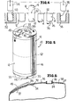
- FIG. 10 wherein there is illustrated a typical can which may be formed in accordance with this invention, the can being generally identified by the numeral 10.
- the can 10 includes a lower half 12 and an upper half 14 which are joined together in sealed relation.
- the lower half 12 includes a cylindrical body 16 having an integral domed bottom 18 which is generally hemispherical in configuration.
- the domed bottom 18 has projecting downwardly therefrom a plurality of bulges or projections 20 in the form of feet.
- the projections 20 are generally circumferentially spaced about the bottom 18 and project downwardly therebelow sufficiently to compensate for any bowing or further doming of the bottom 18 due to internal pressures within the can.
- the upper can half 14 includes a domed top 22 which may also be generally of hemispherical shape if so desired.
- the domed top 22, as is best shown in Figure 6, is provided with a central opening 24, the opening 24 being a filling opening.
- the two halves 12, 14 are joined together at their open ends, preferably by internesting and bonding as will be described hereinafter, and thus the resultant can 10 has no opening therein except for the filling opening 24.
- the filling opening 24, as is best shown in Figure 6, is closed by a filler plug 26.
- the filler plug may be permanently installed or may be removable for dispensing the contents of the can 10.
- the filler plug could be in the form of a threaded fitment having a closure cap and the can could be inverted and used with a dispenser.
- the can top 22 may be of the easy opening type.
- the illustrated can top 22 is of the easy opening type and is provided with a dispensing opening 28 and a vent opening 30 which are closed by molded plastic plugs 32 and 34, respectively.
- the plugs 32 and 34 are bonded to the underside of a tape 36 which, in turn, for a large portion of its length is peel- ably bonded to the can top 22.
- a terminal portion 38 of the tape 36 will be permanently bonded to the can top 22 so that after the can has been opened by peeling back the tape 36, the tap 36 and the plastic plugs 32 and 34 remain adhered to the can.
- the tape 36 has a reversely folded portion 40 in the form of a pull ring to facilitate the peeling the tape from the can top 22.
- the filler plug 26 may either be utilized to hold the tape 36 adhered to the can top 22, the tape 36 may have an opening (not shown) of a sufficient size to permit the tape 36 to be drawn over the filler plug in the opening process.
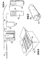
- sheet metal body blanks 42 preferably aluminum blanks
- a forming apparatus 44 which is schematically illustrated as including a female die 46 and a cooperating punch 48 which serves to draw the metal blank 42 into the form of a cup-shaped component generally identified by the numeral 50.
- the cup-shaped component includes a flat bottom 52 and an upwardly flared tapered body 54.
- the can components 50 after they have been formed, are automatically stacked by machinery (not shown) in a nested relation to form a stack 56. Although only six can components 50 have been illustrated as being stacked, it is to be understood that a large number of can components 50 will be stacked in a single stack, the number being on the order of fifty can components.
- the stacked can components 50 are then encircled within a sleeve-type wrapper 58 which may be of any construc-. tion but generally is in the form of a bag having a closable end 60.
- the wrapped stacks 56 of can components 50 are then placed in a suitable container for shipment.
- the wrapped stacks 56 are illustrated as having been placed in a conventional paperboard container or box 62 which is then closed in the normal manner and is ready for shipment. Since the stacks 56 are of a high density, it is to be understood that the shipping cost per can body component 50 will be relatively low.
- the can components 50 are converted into upper and lower can halves.
- the same can components 50 be utilized in the formation of both lower can halves 12 and upper can halves 14.
- the tapered can components'50 may be of different sizes, one size forming the lower can half 12 and another size for forming the upper can half 14.
- the same can component 50 is used in the forming of both can halves.
- a tapered can component 50 is placed in a suitable reforming die 52 and is reformed by means of a suitable punch 54 so as to have the configuration of the previously described can lower half 12.
- another of the tapered can components 50 is placed in a female die 56 and is reshaped therein by means of a punch 58.
- the reshaped can component 50 becomes the upper can half 14.
- the upper can half 14 has a free end portion 60 of a reduced diameter for telescoping in the upper end of the lower can half 12.
- the internested portions of the can halves 12 and 14 are then sealed by a high strength bond to form a seam 62 which will withstand high internal pressures within the can 10 so that it may be utilized for the packaging of carbonated beverages and other products presenting high internal pressures within the can 10.
- the completed cans 10 may also be provided with a suitable label for identifying the product, or suitable indicia may be applied to the bodies either after forming of the can halves or after the assembling thereof to form cans.
Landscapes
- Engineering & Computer Science (AREA)
- Mechanical Engineering (AREA)
- Rigid Containers With Two Or More Constituent Elements (AREA)
- Stackable Containers (AREA)
Applications Claiming Priority (2)
| Application Number | Priority Date | Filing Date | Title |
|---|---|---|---|
| US10605579A | 1979-12-21 | 1979-12-21 | |
| US106055 | 1979-12-21 |
Publications (2)
| Publication Number | Publication Date |
|---|---|
| EP0031254A2 true EP0031254A2 (de) | 1981-07-01 |
| EP0031254A3 EP0031254A3 (de) | 1982-01-13 |
Family
ID=22309236
Family Applications (1)
| Application Number | Title | Priority Date | Filing Date |
|---|---|---|---|
| EP80304647A Withdrawn EP0031254A3 (de) | 1979-12-21 | 1980-12-19 | Verfahren zur Herstellung von Metallbüchsen |
Country Status (9)
| Country | Link |
|---|---|
| EP (1) | EP0031254A3 (de) |
| JP (1) | JPS5695436A (de) |
| AU (1) | AU6507480A (de) |
| BR (1) | BR8008366A (de) |
| DK (1) | DK539180A (de) |
| ES (1) | ES497967A0 (de) |
| GR (1) | GR72844B (de) |
| IL (1) | IL61582A0 (de) |
| ZA (1) | ZA807949B (de) |
Family Cites Families (4)
| Publication number | Priority date | Publication date | Assignee | Title |
|---|---|---|---|---|
| US3695084A (en) * | 1970-11-24 | 1972-10-03 | Reynolds Metals Co | Nestable container and apparatus for and method of making same |
| US3811393A (en) * | 1973-01-12 | 1974-05-21 | Stolle Corp | Manufacture of cans and the like |
| CH608196A5 (en) * | 1976-03-08 | 1978-12-29 | Vogel Bmw Ag | Method for the production of a sheet-metal container |
| GB1546849A (en) * | 1976-09-15 | 1979-05-31 | British Aluminium Co Ltd | Method of making metal containers |
-
1980
- 1980-11-28 IL IL61582A patent/IL61582A0/xx unknown
- 1980-12-04 AU AU65074/80A patent/AU6507480A/en not_active Abandoned
- 1980-12-17 GR GR63684A patent/GR72844B/el unknown
- 1980-12-18 DK DK539180A patent/DK539180A/da unknown
- 1980-12-19 ZA ZA00807949A patent/ZA807949B/xx unknown
- 1980-12-19 EP EP80304647A patent/EP0031254A3/de not_active Withdrawn
- 1980-12-19 BR BR8008366A patent/BR8008366A/pt unknown
- 1980-12-19 ES ES497967A patent/ES497967A0/es active Granted
- 1980-12-19 JP JP17905880A patent/JPS5695436A/ja active Pending
Also Published As
| Publication number | Publication date |
|---|---|
| DK539180A (da) | 1981-06-22 |
| IL61582A0 (en) | 1980-12-31 |
| JPS5695436A (en) | 1981-08-01 |
| ES8205593A1 (es) | 1982-06-16 |
| AU6507480A (en) | 1981-06-25 |
| ES497967A0 (es) | 1982-06-16 |
| ZA807949B (en) | 1982-04-28 |
| EP0031254A3 (de) | 1982-01-13 |
| GR72844B (de) | 1983-12-07 |
| BR8008366A (pt) | 1981-07-07 |
Similar Documents
| Publication | Publication Date | Title |
|---|---|---|
| US3232469A (en) | Frusto-conical label and method of making the same | |
| US5485914A (en) | Composite article carrier | |
| US3844443A (en) | Easy-open container and method of making same | |
| US3204849A (en) | Hexagonal, corrugated shipping container | |
| US2943732A (en) | Package and container forming part thereof | |
| US3506459A (en) | Tamper-proof multiple compartment package | |
| US3921897A (en) | Collapsible container and package | |
| US20090241477A1 (en) | Methods of Packaging Using Multi-Compartment Containers | |
| US4267928A (en) | Composite container structure | |
| US9725204B2 (en) | Paper-based cylindrical bottle | |
| US7124890B2 (en) | Case ready stackable tray designs | |
| US3081926A (en) | Containers and closures therefor | |
| CN101486393A (zh) | 具有新型取出结构的纸箱 | |
| US2412178A (en) | Metal stacking container | |
| US5692634A (en) | Rigid packaging using gas-permeable membrane | |
| US5014872A (en) | Sleeved containers with thin film lining | |
| US5687847A (en) | Carton having divider panel for two-tier can package | |
| US3517475A (en) | Method of packaging | |
| US3739827A (en) | Disposable container | |
| US3187932A (en) | Container and method of making the same or the like | |
| US3208626A (en) | Container closure and package including same | |
| EP2658792B1 (de) | Flexibler folienbehälter | |
| US5477977A (en) | Thin-walled can having a nestable/stackable bottom support ring | |
| EP0044591B1 (de) | Behältersammelpackung und Herstellungsverfahren dafür | |
| WO1998022364A1 (en) | Resealable beverage container and top therefor |
Legal Events
| Date | Code | Title | Description |
|---|---|---|---|
| PUAI | Public reference made under article 153(3) epc to a published international application that has entered the european phase |
Free format text: ORIGINAL CODE: 0009012 |
|
| AK | Designated contracting states |
Designated state(s): AT BE DE FR GB IT NL SE |
|
| PUAL | Search report despatched |
Free format text: ORIGINAL CODE: 0009013 |
|
| AK | Designated contracting states |
Designated state(s): AT BE DE FR GB IT NL SE |
|
| STAA | Information on the status of an ep patent application or granted ep patent |
Free format text: STATUS: THE APPLICATION IS DEEMED TO BE WITHDRAWN |
|
| 18D | Application deemed to be withdrawn |
Effective date: 19821218 |
|
| RIN1 | Information on inventor provided before grant (corrected) |
Inventor name: ROTH, DONALD J. |