EP0031422A1 - Dispositif pour la fabrication de tubes d'une longueur prédéterminée - Google Patents
Dispositif pour la fabrication de tubes d'une longueur prédéterminée Download PDFInfo
- Publication number
- EP0031422A1 EP0031422A1 EP80106713A EP80106713A EP0031422A1 EP 0031422 A1 EP0031422 A1 EP 0031422A1 EP 80106713 A EP80106713 A EP 80106713A EP 80106713 A EP80106713 A EP 80106713A EP 0031422 A1 EP0031422 A1 EP 0031422A1
- Authority
- EP
- European Patent Office
- Prior art keywords
- wire
- tube
- pipe
- welding
- tubular structure
- Prior art date
- Legal status (The legal status is an assumption and is not a legal conclusion. Google has not performed a legal analysis and makes no representation as to the accuracy of the status listed.)
- Granted
Links
Images


Classifications
-
- B—PERFORMING OPERATIONS; TRANSPORTING
- B21—MECHANICAL METAL-WORKING WITHOUT ESSENTIALLY REMOVING MATERIAL; PUNCHING METAL
- B21C—MANUFACTURE OF METAL SHEETS, WIRE, RODS, TUBES, PROFILES OR LIKE SEMI-MANUFACTURED PRODUCTS OTHERWISE THAN BY ROLLING; AUXILIARY OPERATIONS USED IN CONNECTION WITH METAL-WORKING WITHOUT ESSENTIALLY REMOVING MATERIAL
- B21C37/00—Manufacture of metal sheets, rods, wire, tubes, profiles or like semi-manufactured products, not otherwise provided for; Manufacture of tubes of special shape
- B21C37/06—Manufacture of metal sheets, rods, wire, tubes, profiles or like semi-manufactured products, not otherwise provided for; Manufacture of tubes of special shape of tubes or metal hoses; Combined procedures for making tubes, e.g. for making multi-wall tubes
- B21C37/15—Making tubes of special shape; Making tube fittings
- B21C37/22—Making finned or ribbed tubes by fixing strip or like material to tubes
- B21C37/26—Making finned or ribbed tubes by fixing strip or like material to tubes helically-ribbed tubes
-
- F—MECHANICAL ENGINEERING; LIGHTING; HEATING; WEAPONS; BLASTING
- F16—ENGINEERING ELEMENTS AND UNITS; GENERAL MEASURES FOR PRODUCING AND MAINTAINING EFFECTIVE FUNCTIONING OF MACHINES OR INSTALLATIONS; THERMAL INSULATION IN GENERAL
- F16L—PIPES; JOINTS OR FITTINGS FOR PIPES; SUPPORTS FOR PIPES, CABLES OR PROTECTIVE TUBING; MEANS FOR THERMAL INSULATION IN GENERAL
- F16L9/00—Rigid pipes
- F16L9/02—Rigid pipes of metal
- F16L9/04—Reinforced pipes
-
- F—MECHANICAL ENGINEERING; LIGHTING; HEATING; WEAPONS; BLASTING
- F28—HEAT EXCHANGE IN GENERAL
- F28F—DETAILS OF HEAT-EXCHANGE AND HEAT-TRANSFER APPARATUS, OF GENERAL APPLICATION
- F28F1/00—Tubular elements; Assemblies of tubular elements
- F28F1/10—Tubular elements and assemblies thereof with means for increasing heat-transfer area, e.g. with fins, with projections, with recesses
- F28F1/12—Tubular elements and assemblies thereof with means for increasing heat-transfer area, e.g. with fins, with projections, with recesses the means being only outside the tubular element
- F28F1/34—Tubular elements and assemblies thereof with means for increasing heat-transfer area, e.g. with fins, with projections, with recesses the means being only outside the tubular element and extending obliquely
- F28F1/36—Tubular elements and assemblies thereof with means for increasing heat-transfer area, e.g. with fins, with projections, with recesses the means being only outside the tubular element and extending obliquely the means being helically wound fins or wire spirals
Definitions
- the invention relates to a device for producing pipes of a predetermined length, which carry a wire coil on their outer surface.
- Heat exchange tubes have become known from FR-PS 1 527 478 (MECANO BUNDY). B. suitable for evaporators of refrigerators and the like. A wire coil is wound onto the jacket of a double-walled tube in order to enlarge the heat-emitting surface of the tube. In the prior publication, a device for producing such pipes is also described.
- US Pat. No. 2,691,813 describes a method for producing heat exchange elements which are intended in particular for evaporators of cooling devices.
- a tube with a circular cross section is shaped into a desired shape, e.g. B. in the form of a coil.
- the tube jacket is then flattened so that a D-shaped cross section results.
- Solder wire is then applied to the coil in the form of an elongated coil. This arrangement is placed on a plate-shaped support element.
- the tube is connected to the support plate by heating the arrangement above the melting point of the solder wire.
- European patent application 0 000 369 has disclosed a thin-walled metal tube made of a metal strip bent transversely to its longitudinal axis and which is wrapped with a helical wire or strip.
- the connection between the edge regions of the bent metal strip is made by a connecting means which is arranged in the gap between the edge region and which fills the gap as a result of the gap capillarity and which solidifies on cooling.
- the connecting means which melts under the influence of heat and can flow into the gap, can be applied to the bent metal strip together with the wire or tape coil before the edge areas are connected.
- Pipe pieces that have a wire coil on their outer jacket have the advantage of a higher radial load capacity compared to pipes without a wire coil. Because of the "cold connection possibility", such pipes are particularly suitable for areas of application in which welding or soldering of the pipe to the support plate is eliminated for technical or price reasons, for. B. for solar roofs through which a heat exchange medium flows.
- the wire helix is soldered onto the tube jacket while passing through a soldering furnace, then the material properties of the wire of the helix are changed by the heating and subsequent cooling.
- the wire must have a hardness for the subsequent cold joining process which is substantially greater than the hardness of the associated support plate or the like, so that the helical tips can penetrate into the material of the support plate without changing the cross section. Practical experience has shown, however, that the hardness of the wire decreases considerably with the specified soldering process, as with other soldering or welding processes.
- Another problem with the cold connection arises from the inadequate balancing of the thermal stresses between a pipe with a soldered wire coil and the support plate. If the pipe z. B. is used as a casing for a tubular heater and this on the bottom of an electrically heated device, for. B. a frying pan or a deep fryer, then arise due to the different expansion in the heating and cooling - z. B. when pouring on the food to be roasted - considerable thermal stresses between the floor and the tubular heater. These can lead to the cold connection "breaking out" after a corresponding period of use of the device, so that the tubular heating element of partially or completely loosens the floor.
- the wire coil should have a certain freedom of movement with respect to the tube, so that thermal stresses are compensated for.
- the wire helix must be connected to the tube at least at the connection ends, so that the wire helix does not "open” and so that the prestressing of the wire helix desired to increase the radial load capacity of the tube is maintained.
- a processing of the connection ends, for. B. shortening by cutting to a certain extent may be possible so that the z. B. when laying a solar roof or energy roof resulting inevitable shifts within a certain tolerance range and a durable connection between the pipes can be achieved with each other and with manifolds.
- the invention has for its object to provide a device so that tubes can be produced with wire helix, which are improved so that the above requirements are met. Furthermore, a corresponding piece of pipe with a wire helix and a heat exchange element is proposed.
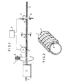
- a strip-shaped starting material 2 is deformed in a continuous pass to form a tubular structure 3.
- the tube seam formed by the edges of the band-shaped starting material is used in the continuous pass through the device 1 welded.
- the deforming and welding device 1 is assigned a winding device 4.
- a wire 6 is unwound from a supply spool 5, the rotatability of which is braked accordingly, and is wound helically onto the tubular structure 3 under pretension.
- a downstream welding device 7 is controlled by a control device 8 as a function of the throughput speed of the strip-shaped starting material 2 or the tubular structure 3 in such a way that the welding device 7 is energized in certain time intervals.
- the current flowing from the welding device 7 onto the helically wound wire 6 flows out via the grounded tubular structure 3.
- the duration of the current flow as a function of the throughput speed of the band-shaped starting material 2 is set such that a few, preferably three, windings of the wire 6 are welded to the jacket of the tubular structure 3.
- the corresponding weld is indicated at 9 in each case.
- a control device 8 also controls a separation device 10, which accordingly operates when a pipe length corresponding to the distance between two welding points 9 or a multiple thereof has expired from the welding device 7. This means that the tube is cut off in the middle of a welding point 9. Accordingly, a piece of pipe 11 of a certain predetermined length is created, which carries a wire coil, in which at least one coil winding is connected to the pipe jacket by a weld at the pipe end.
- the control device 8 is in each case set to the throughput speed of the strip-shaped starting material, or the throughput speed can be scanned, for example, by rollers (not shown) resting on the strip-shaped material.
- the length of the pipe section 11 is adjusted by a corresponding change the timing with which the welding device 7 and thus inevitably also the cutting device 10 is controlled.
- the pipe sections 11 can now - if desired, after appropriate deformation z. B. in a hairpin shape - on a support plate, not shown, for. B. cold pressed onto the underside of a sheet metal sheet intended for the production of a solar sheet cover.
- the lips of the wire helix 6 which abut the sheet metal web penetrate into the z. B. existing aluminum or copper sheet.
- the material of the sheet metal web lying between the helical windings is pushed away to the side with increasing penetration, so that the "undercuts" between the largest diameter of the wire and the line of contact with the pipe jacket are filled.
- the wire helix is continuously soldered onto the tube, then the thermal windings are displaced in the direction of the tube axis relative to the support plate.
- the wire coil gradually works out of the anchoring achieved by filling in the “undercuts”, as a result of which the cold connection is deteriorated until the pipe detaches from the supporting plate.
- the wire coil rests relative to the support plate while the tube expands or contracts in the wire coil. Accordingly, the cold connection is not deteriorated by thermal stresses.
- connection must be designed in such a way that several hundred connections can be made in one day by a semi-skilled worker during assembly at the construction site.
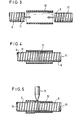
- FIGS. 3 to 5 show a solution to this problem.
- a shrink tube piece 12 is used which has a larger diameter than the associated spiral tube 11.
- the tube piece consists of a plastic material which contracts under the action of heat, that is to say shrinks.
- the ends of two spiral tubes are pushed into the shrink tube piece 12. If this is not possible, the piece of shrink tubing can first be pushed onto one of the tubes. Then when the adjacent energy roof element has been fitted, the tube piece 12 is then slipped over the connection point. Subsequently, as shown in FIG. 5, the tube piece 12 is heated by means of a hot air blower 13, whereby it contracts.
- the windings of the wire coil 6 penetrate into the material of the tube piece 12. This anchoring results in a very high tensile strength of the connection, which is of the order of the spiral tube 11.
- the connection is accordingly
- connection is somewhat elastic and flexible. Both axial thermal stresses and slight buckling stresses can thus be compensated for.
- Figure 6 shows that the "shrink tubing connection" is in itself also suitable for connecting smooth pipes 14, provided that there are no excessive tensile stresses on the connection points.
- FIG. 7 shows the cross section of a connection point at which the pipe end 15 of one of the pipes 14 has been slightly widened, so that the end 16 of the other pipe can be inserted into the widened point 15.
- a connection is more durable than the connection shown in FIG. 6. It is particularly durable if the tubes 14 carry a wire coil up to the connection points 15 and 16, which is anchored in the end regions of the shrink tube piece 12.
- FIG. 8 shows a solution in which annular grooves 17 are machined into the ends of the tubes 14. In the shrinking process, the material of the shrink tube piece 12 penetrates into the grooves 17, which results in a corresponding anchoring.
- FIG. 9 shows the connection of an energy roof element 18 to a manifold 19.
- Pipe pieces 20 are fastened to a metal sheet 21 by means of any connection method, but preferably by means of a cold connection.
- a wire helix was pushed over each of the tube pieces 20, but it had a considerably larger diameter than the tubes 20.
- lateral loops 22 are pressed out of the wire helix, which are located next to the tube 20 in the Anchor support plate 21.
- the pressing tool used which can optionally also be a roll pass, has a channel which is shaped in accordance with the tube diameter 20 and which receives the tube.
- the ends of the tubes 20 are allowed to protrude beyond the support plate 21. Some windings of a wire coil 6 are applied to these ends by the method described at the beginning. The connection then again takes place by means of shrink tube pieces 12.
- FIG. 11 shows an exemplary embodiment of a connection point in an energy roof with pipes 23 running across the roof.
- the pipe ends are angled at 24.
- the ends in turn have some windings of the wire helix 6.
- the support plates 25 of two adjacent energy roof elements are pushed together, the ends 24 of the tubes 23 being pushed into the shrink tube piece 12.
- the piece of shrink tubing is then heated, as shown in FIG. 5. Thereafter, the bent-up edges 26 of the sheets 25 are flanged using a known continuous tool, whereby an absolutely tight roof outer skin is produced.
- the spot welding of the wire coil 6 to the tubes 11 can be carried out particularly expediently, for example by means of four tools, which are periodically advanced radially inwards in the direction of the tube axis.
Landscapes
- Engineering & Computer Science (AREA)
- Mechanical Engineering (AREA)
- General Engineering & Computer Science (AREA)
- Physics & Mathematics (AREA)
- Geometry (AREA)
- Thermal Sciences (AREA)
- Butt Welding And Welding Of Specific Article (AREA)
- Wire Processing (AREA)
- Lining Or Joining Of Plastics Or The Like (AREA)
- Rigid Pipes And Flexible Pipes (AREA)
- Heat-Exchange Devices With Radiators And Conduit Assemblies (AREA)
Priority Applications (1)
| Application Number | Priority Date | Filing Date | Title |
|---|---|---|---|
| AT80106713T ATE8213T1 (de) | 1979-11-09 | 1980-10-31 | Vorrichtung zur herstellung von rohrstuecken vorgegebener laenge. |
Applications Claiming Priority (2)
| Application Number | Priority Date | Filing Date | Title |
|---|---|---|---|
| DE2945282A DE2945282C2 (de) | 1979-11-09 | 1979-11-09 | Rohrstück für Wärmeaustauscher |
| DE2945282 | 1979-11-09 |
Publications (2)
| Publication Number | Publication Date |
|---|---|
| EP0031422A1 true EP0031422A1 (fr) | 1981-07-08 |
| EP0031422B1 EP0031422B1 (fr) | 1984-07-04 |
Family
ID=6085578
Family Applications (1)
| Application Number | Title | Priority Date | Filing Date |
|---|---|---|---|
| EP80106713A Expired EP0031422B1 (fr) | 1979-11-09 | 1980-10-31 | Dispositif pour la fabrication de tubes d'une longueur prédéterminée |
Country Status (4)
| Country | Link |
|---|---|
| EP (1) | EP0031422B1 (fr) |
| JP (1) | JPS5684192A (fr) |
| AT (1) | ATE8213T1 (fr) |
| DE (1) | DE2945282C2 (fr) |
Cited By (4)
| Publication number | Priority date | Publication date | Assignee | Title |
|---|---|---|---|---|
| US5195675A (en) * | 1990-03-27 | 1993-03-23 | Verolme Machinefabriek Ijsselmonde B.V. | Method for producing a composite pipe |
| DE4330957A1 (de) * | 1993-09-09 | 1995-03-16 | Mannesmann Ag | Anlage zur Herstellung von Wärmetauscherrohren |
| DE102008017452A1 (de) * | 2008-04-05 | 2009-10-15 | Metallwerk Möllersdorf Handelsgesellschaft m.b.H. | Verfahren zum Isolieren von Verbindungsstellen bei Rohrleitungen mit Korrosionsschutzisolierung |
| CN115846787A (zh) * | 2023-03-02 | 2023-03-28 | 武汉松盛光电科技有限公司 | 成环装置的控制方法、控制装置、成环装置及存储介质 |
Citations (11)
| Publication number | Priority date | Publication date | Assignee | Title |
|---|---|---|---|---|
| DE944787C (de) * | 1950-10-12 | 1956-06-21 | Aerofin Corp | Verfahren und Vorrichtung zum Aufbringen von Waermeaustauschrippen auf Heiz- oder Kuehlrohre |
| AT246539B (de) * | 1963-07-20 | 1966-04-25 | Franciscus Roffelsen | Vorrichtung zum Herstellen von metallischen Wärmeaustauschrohren mit einer schraubenförmig darauf aufgewickelten Drahtwendel |
| US3460225A (en) * | 1966-09-26 | 1969-08-12 | Resistance Welder Corp | Method of forming a wire condenser mat welder |
| DE2146773A1 (de) * | 1971-09-16 | 1973-03-22 | Mannesmann Roehren Werke Ag | Verfahren zum herstellen von laengsnahtgeschweissten rohren |
| DE2461249A1 (de) * | 1974-12-23 | 1976-06-24 | Elpag Ag Chur | Verfahren zum befestigen von verbindungsgliedern mit einem metallteil |
| GB1474929A (en) * | 1973-11-27 | 1977-05-25 | Atomenergi Ab | Method of joining tube coupling components made of cross-linked polymers |
| EP0000369A1 (fr) * | 1977-07-08 | 1979-01-24 | Elpag Ag Chur | Tube métallique à paroi mince, procédé de fabrication, et son utilisation |
| DE2803413A1 (de) * | 1978-01-26 | 1979-08-02 | Wega Ag | Verfahren zur herstellung eines metall-rippenkoerper-waermetauschers und nach einem derartigen verfahren hergestellter waermetauscher |
| DE2804644A1 (de) * | 1978-02-03 | 1979-08-09 | Wega Ag | Verfahren bzw. einrichtung zur herstellung eines metall-rippenkoerper- waermetauschers |
| DE2805921A1 (de) * | 1978-02-13 | 1979-08-16 | Wega Ag | Verfahren bzw. einrichtung zur herstellung eines metall-rippenkoerper- waermetauschers |
| DE2814455A1 (de) * | 1978-04-04 | 1979-10-18 | Elpag Ag Chur | Waermeaustauschelement |
Family Cites Families (10)
| Publication number | Priority date | Publication date | Assignee | Title |
|---|---|---|---|---|
| DE524552C (de) * | 1927-04-27 | 1931-05-08 | Bundy Tubing Co | Verfahren zur Herstellung von Rippenrohren |
| GB470978A (en) * | 1936-02-25 | 1937-08-25 | Henri Andre Richard | Improvements in and relating to radiators for heating buildings |
| DE834388C (de) * | 1949-11-01 | 1952-03-20 | Eisenwerk Kritzler | Vorrichtung zum Herstellen von Rippenrohren |
| DE1719770U (de) * | 1956-01-24 | 1956-04-05 | Gustav Rasmussen | Vorrichtung zur herstellung von rippenrohren. |
| US3047712A (en) * | 1961-02-23 | 1962-07-31 | American Mach & Foundry | Method and apparatus for welding striplike material to curved surfaces |
| CH430110A (de) * | 1964-09-04 | 1967-02-15 | Stramax Ag | Strahlungseinrichtung mit an beheizten oder gekühlten Trägern befestigten Wärme- und Kälteverteilorganen |
| US3672446A (en) * | 1969-01-21 | 1972-06-27 | Airco Inc | Ambient air vaporizer |
| US3909898A (en) * | 1974-12-04 | 1975-10-07 | Gen Electric | Method and apparatus for manufacturing a helically finned heat exchanger |
| NL171494C (nl) * | 1975-11-11 | 1983-04-05 | Gouda Holland Bv | Warmtewisselaar. |
| DE2737643A1 (de) * | 1977-08-20 | 1979-03-01 | Messerschmitt Boelkow Blohm | Mechanische waermetraegerfuehrung-rippenverbindung fuer heiz- und kuehlkoerper |
-
1979
- 1979-11-09 DE DE2945282A patent/DE2945282C2/de not_active Expired
-
1980
- 1980-10-31 AT AT80106713T patent/ATE8213T1/de not_active IP Right Cessation
- 1980-10-31 EP EP80106713A patent/EP0031422B1/fr not_active Expired
- 1980-11-08 JP JP15753680A patent/JPS5684192A/ja active Pending
Patent Citations (11)
| Publication number | Priority date | Publication date | Assignee | Title |
|---|---|---|---|---|
| DE944787C (de) * | 1950-10-12 | 1956-06-21 | Aerofin Corp | Verfahren und Vorrichtung zum Aufbringen von Waermeaustauschrippen auf Heiz- oder Kuehlrohre |
| AT246539B (de) * | 1963-07-20 | 1966-04-25 | Franciscus Roffelsen | Vorrichtung zum Herstellen von metallischen Wärmeaustauschrohren mit einer schraubenförmig darauf aufgewickelten Drahtwendel |
| US3460225A (en) * | 1966-09-26 | 1969-08-12 | Resistance Welder Corp | Method of forming a wire condenser mat welder |
| DE2146773A1 (de) * | 1971-09-16 | 1973-03-22 | Mannesmann Roehren Werke Ag | Verfahren zum herstellen von laengsnahtgeschweissten rohren |
| GB1474929A (en) * | 1973-11-27 | 1977-05-25 | Atomenergi Ab | Method of joining tube coupling components made of cross-linked polymers |
| DE2461249A1 (de) * | 1974-12-23 | 1976-06-24 | Elpag Ag Chur | Verfahren zum befestigen von verbindungsgliedern mit einem metallteil |
| EP0000369A1 (fr) * | 1977-07-08 | 1979-01-24 | Elpag Ag Chur | Tube métallique à paroi mince, procédé de fabrication, et son utilisation |
| DE2803413A1 (de) * | 1978-01-26 | 1979-08-02 | Wega Ag | Verfahren zur herstellung eines metall-rippenkoerper-waermetauschers und nach einem derartigen verfahren hergestellter waermetauscher |
| DE2804644A1 (de) * | 1978-02-03 | 1979-08-09 | Wega Ag | Verfahren bzw. einrichtung zur herstellung eines metall-rippenkoerper- waermetauschers |
| DE2805921A1 (de) * | 1978-02-13 | 1979-08-16 | Wega Ag | Verfahren bzw. einrichtung zur herstellung eines metall-rippenkoerper- waermetauschers |
| DE2814455A1 (de) * | 1978-04-04 | 1979-10-18 | Elpag Ag Chur | Waermeaustauschelement |
Cited By (6)
| Publication number | Priority date | Publication date | Assignee | Title |
|---|---|---|---|---|
| US5195675A (en) * | 1990-03-27 | 1993-03-23 | Verolme Machinefabriek Ijsselmonde B.V. | Method for producing a composite pipe |
| DE4330957A1 (de) * | 1993-09-09 | 1995-03-16 | Mannesmann Ag | Anlage zur Herstellung von Wärmetauscherrohren |
| DE102008017452A1 (de) * | 2008-04-05 | 2009-10-15 | Metallwerk Möllersdorf Handelsgesellschaft m.b.H. | Verfahren zum Isolieren von Verbindungsstellen bei Rohrleitungen mit Korrosionsschutzisolierung |
| DE102008017452B4 (de) * | 2008-04-05 | 2013-01-17 | Metallwerk Möllersdorf Handelsgesellschaft m.b.H. | Verfahren zum Isolieren von Verbindungsstellen bei Rohrleitungen mit Korrosionsschutzisolierung |
| CN115846787A (zh) * | 2023-03-02 | 2023-03-28 | 武汉松盛光电科技有限公司 | 成环装置的控制方法、控制装置、成环装置及存储介质 |
| CN115846787B (zh) * | 2023-03-02 | 2023-06-02 | 武汉松盛光电科技有限公司 | 成环装置的控制方法、控制装置、成环装置及存储介质 |
Also Published As
| Publication number | Publication date |
|---|---|
| JPS5684192A (en) | 1981-07-09 |
| EP0031422B1 (fr) | 1984-07-04 |
| DE2945282C2 (de) | 1987-04-23 |
| DE2945282A1 (de) | 1981-05-21 |
| ATE8213T1 (de) | 1984-07-15 |
Similar Documents
| Publication | Publication Date | Title |
|---|---|---|
| EP1104839B1 (fr) | Dispositif d'échappement pour un véhicule, véhicule et procédé de fabrication de ce dispositif | |
| DE69311428T2 (de) | Verfahren zur Herstellung eines Widerstandes zum Verschweissen in Form eines Netzes, eine mit diesem Verfahren hergestellter Widerstand für das Zusammenfügen paralleller oder transversaler Kunststoffröhren und damit ausgerüstete Rohrverzweigung | |
| DE3779839T2 (de) | Verfahren zur verbindung eines kunststoffrohrendes mit einer schweissbaren kunststoffhuelse. | |
| DE2731027C2 (de) | Verfahren zur Herstellung von dünnwandigen Metallrohren | |
| EP0819497B1 (fr) | Procédé de fabrication de tube à nervure | |
| DE2934003A1 (de) | Rohrspiralenpaket fuer waermetauscher und verfahren zur herstellung desselben | |
| EP0031422A1 (fr) | Dispositif pour la fabrication de tubes d'une longueur prédéterminée | |
| DE102006002932A1 (de) | Wärmetauscher und Herstellungsverfahren für Wärmetauscher | |
| EP0031866A1 (fr) | Procédé pour la fabrication d'un appareil de chauffage ou d'un élément échangeur de chaleur | |
| DE69917976T2 (de) | Verfahren zum Herstellen eines Gehäuses eines Schalldämpfers und ein solches Gehäuse | |
| EP1061240A2 (fr) | Procédé de raccordement d'éléments d'un système d'échappement et ainsi qu'un système d'échappement | |
| DE2461249A1 (de) | Verfahren zum befestigen von verbindungsgliedern mit einem metallteil | |
| EP0032965B1 (fr) | Procédé pour la fabrication d'éléments d'échangeur de chaleur et dispositif pour la réalisation de ce procédé | |
| DE2814455A1 (de) | Waermeaustauschelement | |
| DE3643794C1 (en) | Method for the production of a spiral falling-film evaporator tube | |
| EP0168637A2 (fr) | Chaudière à gaz, en particulier chaudière à condensation, avec couloir de fumée à spirale, méthode pour fabriquer une telle chaudière et chaudière à gaz fabriquée avec une telle méthode | |
| DE10211703B4 (de) | Verfahren zur Herstellung einer feuchtigkeitsdichten Verbindung | |
| DE19753759A1 (de) | Absorber für Sonnenenergie und Verfahren zur Herstellung desselben | |
| DE2208746A1 (de) | Waermetauscher | |
| DE3545424A1 (de) | Rohrheizkoerper-heizeinheit sowie verfahren zu deren herstellung | |
| DE19749447C2 (de) | Umgeformtes Doppelwandrohr aus Metall sowie Verfahren zu seiner Herstellung | |
| CH662874A5 (de) | Elektrisch beheizbares band zur herstellung einer muffenverbindung fuer waermeisolierte leitungsrohre und verfahren zur herstellung eines solchen bandes. | |
| EP0005511B1 (fr) | Procédé pour la fabrication en série de tubes thermiques | |
| DE2365761C3 (de) | Verbindungselement zum mechanischen Verbinden zweier Metallteile | |
| DE69211005T2 (de) | Wärmetauschglied sowie verfahren zur herstellung desselben |
Legal Events
| Date | Code | Title | Description |
|---|---|---|---|
| PUAI | Public reference made under article 153(3) epc to a published international application that has entered the european phase |
Free format text: ORIGINAL CODE: 0009012 |
|
| AK | Designated contracting states |
Designated state(s): AT CH FR GB IT LI SE |
|
| 17P | Request for examination filed |
Effective date: 19820108 |
|
| RBV | Designated contracting states (corrected) |
Designated state(s): AT CH FR GB IT LI SE |
|
| ITF | It: translation for a ep patent filed | ||
| GRAA | (expected) grant |
Free format text: ORIGINAL CODE: 0009210 |
|
| AK | Designated contracting states |
Designated state(s): AT CH FR GB IT LI SE |
|
| REF | Corresponds to: |
Ref document number: 8213 Country of ref document: AT Date of ref document: 19840715 Kind code of ref document: T |
|
| ET | Fr: translation filed | ||
| PLBE | No opposition filed within time limit |
Free format text: ORIGINAL CODE: 0009261 |
|
| STAA | Information on the status of an ep patent application or granted ep patent |
Free format text: STATUS: NO OPPOSITION FILED WITHIN TIME LIMIT |
|
| 26N | No opposition filed | ||
| ITTA | It: last paid annual fee | ||
| PGFP | Annual fee paid to national office [announced via postgrant information from national office to epo] |
Ref country code: SE Payment date: 19931018 Year of fee payment: 14 |
|
| PGFP | Annual fee paid to national office [announced via postgrant information from national office to epo] |
Ref country code: AT Payment date: 19931031 Year of fee payment: 14 |
|
| PG25 | Lapsed in a contracting state [announced via postgrant information from national office to epo] |
Ref country code: AT Effective date: 19941031 |
|
| PG25 | Lapsed in a contracting state [announced via postgrant information from national office to epo] |
Ref country code: SE Effective date: 19941101 |
|
| EAL | Se: european patent in force in sweden |
Ref document number: 80106713.3 |
|
| EUG | Se: european patent has lapsed |
Ref document number: 80106713.3 |
|
| PGFP | Annual fee paid to national office [announced via postgrant information from national office to epo] |
Ref country code: CH Payment date: 19951006 Year of fee payment: 16 |
|
| PGFP | Annual fee paid to national office [announced via postgrant information from national office to epo] |
Ref country code: FR Payment date: 19951013 Year of fee payment: 16 |
|
| PGFP | Annual fee paid to national office [announced via postgrant information from national office to epo] |
Ref country code: GB Payment date: 19951030 Year of fee payment: 16 |
|
| PG25 | Lapsed in a contracting state [announced via postgrant information from national office to epo] |
Ref country code: LI Effective date: 19961031 Ref country code: GB Effective date: 19961031 Ref country code: CH Effective date: 19961031 |
|
| REG | Reference to a national code |
Ref country code: CH Ref legal event code: PL |
|
| GBPC | Gb: european patent ceased through non-payment of renewal fee |
Effective date: 19961031 |
|
| PG25 | Lapsed in a contracting state [announced via postgrant information from national office to epo] |
Ref country code: FR Effective date: 19970630 |
|
| REG | Reference to a national code |
Ref country code: FR Ref legal event code: ST |