EP0031441A2 - Marteau d'impression pour imprimante rapide à percussion - Google Patents
Marteau d'impression pour imprimante rapide à percussion Download PDFInfo
- Publication number
- EP0031441A2 EP0031441A2 EP80107142A EP80107142A EP0031441A2 EP 0031441 A2 EP0031441 A2 EP 0031441A2 EP 80107142 A EP80107142 A EP 80107142A EP 80107142 A EP80107142 A EP 80107142A EP 0031441 A2 EP0031441 A2 EP 0031441A2
- Authority
- EP
- European Patent Office
- Prior art keywords
- hammer
- face
- carrier
- print hammer
- Prior art date
- Legal status (The legal status is an assumption and is not a legal conclusion. Google has not performed a legal analysis and makes no representation as to the accuracy of the status listed.)
- Granted
Links
Images


Classifications
-
- B—PERFORMING OPERATIONS; TRANSPORTING
- B41—PRINTING; LINING MACHINES; TYPEWRITERS; STAMPS
- B41J—TYPEWRITERS; SELECTIVE PRINTING MECHANISMS, i.e. MECHANISMS PRINTING OTHERWISE THAN FROM A FORME; CORRECTION OF TYPOGRAPHICAL ERRORS
- B41J9/00—Hammer-impression mechanisms
- B41J9/02—Hammers; Arrangements thereof
- B41J9/04—Hammers; Arrangements thereof of single hammers, e.g. travelling along printing line
-
- B—PERFORMING OPERATIONS; TRANSPORTING
- B41—PRINTING; LINING MACHINES; TYPEWRITERS; STAMPS
- B41J—TYPEWRITERS; SELECTIVE PRINTING MECHANISMS, i.e. MECHANISMS PRINTING OTHERWISE THAN FROM A FORME; CORRECTION OF TYPOGRAPHICAL ERRORS
- B41J9/00—Hammer-impression mechanisms
- B41J9/02—Hammers; Arrangements thereof
- B41J9/133—Construction of hammer body or tip
Definitions
- This application relates to a print hammer for high speed printers, and more particularly, for high speed printers wherein the type-face-carrier is moved in front of the print hammer for character selection purposes.
- printers are known in which the type-face-carrier is made of a printwheel provided with radially extending resilient pads or fingers each of which bears a character printing element on its extremity.
- Proper positioning of a pad for printing purposes involves two movements, a rectilinear shifting movement of the printwheel along the platen and a rotary movement of the printwheel to present the desired pad in front of the print hammer.
- the printing speed may be increased by having these two movements overlapping each other in time, i.e., the printwheel is rotated while being shifted.
- any printwheel rotation is prohibited until the printwheel path has been cleared by the return of the print hammer.
- the printwheel cannot be positioned too far away from the platen otherwise interference between the hammer head returning to its rest position and the printwheel path might be too long in time, which means that several fingers might hit the hammer head while the printwheel is being rotated, which could result in printwheel damaging, unless the printing speed is being reduced.
- the print hammer has been designed to lift up and over the printwheel so as to clear the space scanned by the printwheel (i.e., printwheel pathl. while said print hammer is on its way back from its impact position to its rest position.
- This printwheel path is cleared right after impact is performed, and rotation of the printwheel for proper positioning of the finger bearing the next character to be printed can be started while the print hammer is traveling back to its rest position.
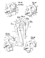
- FIG. 1 a perspective view of the print hammer 1 of this invention is represented.
- the hammer head 2 which is hook shaped is also articulated by being pivotally attached at 3 to a power arm 5.
- the hammer power arm 5 is driven by a plunger-type solenoid 13, the plunger 15 of which pushes the power arm 5 at surface 16 to make it rotate about its pivot 7 and make the hammer head 2 strike the printwheel 11.
- the hammer power arm 5 is restored by restore spring 19, the lower end of which is attached to the support 21 of the frame 9.
- Plunger type solenoid 13 and restore spring 19 constitute drive means for reciprocatably moving the power arm 5 in a plane normal to the surface of the platen cylinder 23.
- FIG. 2A is a view of the print hammer 1 of this invention from the opposite side to that shown in FIG. 1.
- the print hammer 1 positions relative to the printwheel 11 can be seen in FIGS. 2A to 2E showing various phases of the print hammer 1 operation to be described later on.
- the cut-out portion 33 in the hook-shaped hammer head 2 allows the hammer head 2 to pass "through" the plane of the printwheel 11 and not be interfering with that plane while being in the impact position as shown in FIG. 2B.
- This cut-out 33 combined with the lift up and over action provided to the hammer head 2 enables clearance of the printwheel 11 path as soon as the character impacting operation shown on FIG. 2B is performed.
- the hook shape of the hammer head 2 enables clearance of the printwheel 11 path while the print hammer 1 is in its impact position (FIG.
- FIGS. 2A and 4A show the hammer head 2 in the rest position, also represented in FIG. 3.
- the solenoid 13 see FIG. 1
- the solenoid 13 When the solenoid 13 (see FIG. 1) is energized, it begins to move the hammer head 2 toward the platen cylinder 23 (see FIG. 11 in a plane perpendicular to the axis of said cylinder 22.
- the cam 27 is designed such that the cam follower 2a is held under a ledge 27a on the forward or impact stroke (see FIG. 4A1. This prevents the centrifugal forces on the hammer head 2 from causing it to rotate upward. An action such as the latter would cause a machine failure by allowing the hammer head 2 to go over the printwheel 11 and strike the platen cylinder 23, possibly ripping the ribbon (not shown).
- the cam follower 2a during this part of the cycle, from rest position to impact position of the printhammer 1 as well as in rest position, is holding the cam 27 and a resilient member, i.e., leaf spring 31 in their open position (closed denoting position of the leaf spring 31 and cam 27 closest to the frame 91. Further, along in the same stroke with the hammer head 2 moving toward impact position, the cam follower 2a passes the front edge of the cam 27 and the cam leaf spring 31 begins to force the cam 27 into the closed position (see FIG. 2B). This event may occur less than a millimeter from the impact position. Until impact occurs, the hammer head 2 remains stationary to the power arm 5.
- a resilient member i.e., leaf spring 31
- the motion power developed to move the print hammer 1 from rest position toward impact position is provided by energizing the .solenoid 13, of FIG. 1, but the power to the solenoid should be turned off before impact occurs. Impact occurs very quickly, on the order of 100 to 200 microseconds. From the time the cam follower 2a has passed the cam 27 to the end of the impact time, the cam leaf spring 31 has forced the cam 27 into the closed position, setting the stage for print hammer 1 return. It should also be noted on FIG. 2B how the path of the idle pads of the printwheel 11 is kept cleared by the cut out 33 into the hook shaped hammer head 2, while the pad 35 is still bent.
- the return stroke of the hammer head 2 from impact position to rest position is more elaborate than the impact stroke because of the lifting up and over action.
- a momentum transfer occurs at the platen cylinder 23; in this case, sending the hammer head 2 and power arm 5 away from the platen. Since the plunger 15 of solenoid 13 is in contact with the power arm 5 at surface 16, the plunger 15 begins to return also to its rest position.
- the restore spring 19 serves to make the return stroke reliable and controlled.
- Character selection operation i.e., rotation of the printwheel 11 can thus commence as the cam follower 2a strikes the cam 27.
- the printwheel pad 35 bearing the character which was just printed will slide off of the detent section 2b (see FIG. 1) of the hammer head 2.
- the selection operation for the next character to be printed may thus be started before the hammer head 2 has restored to its rest position.
- the cam follower 2a has oriented the hammer head 2 above the printwheel 11.
- the last part of the return stroke is concerned with positioning the hammer head 2, power arm 5 and cam 27 back into their rest positions. This is accomplished by the continued action of restore spring 19 to restore the power arm 5 and solenoid plunger 15. Simultaneously, the return spring 25 urges the hammer head 2 to try and rotate to its rest position. The motion of the hammer head 2 is resisted by the cam 27 and leaf spring 31. However, as the power arm 5 reaches the end of its stroke, the cam follower 2a begins to slide down the transverse slope 27b of the cam 27.
- An alternate method to return spring 25 is to use a knock-down tab that pushes the hammer head 2 down. This is accomplished by having a section (not shown) on the top of the hammer head 2 strike a tab (not shown) in the power frame 9. The motion of the power arm 5 causes the hammer head 2 to rotate down and push the cam 27 to the open position.
- the return spring 25 forces the solenoid plunger 15 to return with the power arm 5.
- the cycle is completed when the print hammer 1 is back into its rest position as shown in FIGS. 2E and 3, and another print hammer cycle can begin.
- the path of the hammer head 2 on its way back from impact position to rest position is represented in FIG. 3 with two restore positions shown to better illustrate the movement of hammer head 2.
- the upper portion of the hammer head 2 has been enlarged on FIGS. 4A-4D to show the cooperation of detailed elements while the print hammer 1 is in each of the four positions mentioned in FIG. 3.
Landscapes
- Accessory Devices And Overall Control Thereof (AREA)
- Character Spaces And Line Spaces In Printers (AREA)
- Impact Printers (AREA)
- Common Mechanisms (AREA)
Applications Claiming Priority (2)
| Application Number | Priority Date | Filing Date | Title |
|---|---|---|---|
| US06/106,613 US4319849A (en) | 1979-12-26 | 1979-12-26 | Print hammer for high speed impact printer |
| US106613 | 1979-12-26 |
Publications (3)
| Publication Number | Publication Date |
|---|---|
| EP0031441A2 true EP0031441A2 (fr) | 1981-07-08 |
| EP0031441A3 EP0031441A3 (en) | 1982-10-27 |
| EP0031441B1 EP0031441B1 (fr) | 1985-03-13 |
Family
ID=22312351
Family Applications (1)
| Application Number | Title | Priority Date | Filing Date |
|---|---|---|---|
| EP80107142A Expired EP0031441B1 (fr) | 1979-12-26 | 1980-11-18 | Marteau d'impression pour imprimante rapide à percussion |
Country Status (8)
| Country | Link |
|---|---|
| US (1) | US4319849A (fr) |
| EP (1) | EP0031441B1 (fr) |
| JP (1) | JPS5693578A (fr) |
| AU (1) | AU530902B2 (fr) |
| BR (1) | BR8008306A (fr) |
| CA (1) | CA1137355A (fr) |
| DE (1) | DE3070287D1 (fr) |
| ES (1) | ES8203044A1 (fr) |
Families Citing this family (4)
| Publication number | Priority date | Publication date | Assignee | Title |
|---|---|---|---|---|
| JPS641080Y2 (fr) * | 1981-01-28 | 1989-01-11 | ||
| DE3424045A1 (de) * | 1983-06-30 | 1985-01-03 | Alps Electric Co., Ltd., Tokio/Tokyo | Typenraddrucker |
| US4686900A (en) * | 1985-12-05 | 1987-08-18 | Xerox Corporation | Impact printer with application of oblique print force |
| US4821614A (en) * | 1986-03-10 | 1989-04-18 | International Business Machines Corporation | Programmable magnetic repulsion punching apparatus |
Family Cites Families (4)
| Publication number | Priority date | Publication date | Assignee | Title |
|---|---|---|---|---|
| FR1597830A (fr) * | 1968-01-29 | 1970-06-29 | ||
| US3574326A (en) * | 1968-03-26 | 1971-04-13 | Donald F Flynn | Actuating mechanism for rotating printing disc |
| CH500073A (de) * | 1968-11-07 | 1970-12-15 | Olympia Werke Ag | Druckwerk für elektrische Büromaschinen |
| DE2629592C2 (de) * | 1976-07-01 | 1986-04-17 | Ibm Deutschland Gmbh, 7000 Stuttgart | Druckhammer für Typendrucker |
-
1979
- 1979-12-26 US US06/106,613 patent/US4319849A/en not_active Expired - Lifetime
-
1980
- 1980-10-16 CA CA000362547A patent/CA1137355A/fr not_active Expired
- 1980-11-03 AU AU64057/80A patent/AU530902B2/en not_active Ceased
- 1980-11-18 DE DE8080107142T patent/DE3070287D1/de not_active Expired
- 1980-11-18 EP EP80107142A patent/EP0031441B1/fr not_active Expired
- 1980-12-15 JP JP17592880A patent/JPS5693578A/ja active Granted
- 1980-12-18 BR BR8008306A patent/BR8008306A/pt not_active IP Right Cessation
- 1980-12-24 ES ES498131A patent/ES8203044A1/es not_active Expired
Also Published As
| Publication number | Publication date |
|---|---|
| JPS5693578A (en) | 1981-07-29 |
| BR8008306A (pt) | 1981-07-07 |
| CA1137355A (fr) | 1982-12-14 |
| AU6405780A (en) | 1981-07-02 |
| ES498131A0 (es) | 1982-02-16 |
| US4319849A (en) | 1982-03-16 |
| DE3070287D1 (en) | 1985-04-18 |
| EP0031441B1 (fr) | 1985-03-13 |
| EP0031441A3 (en) | 1982-10-27 |
| JPS6217549B2 (fr) | 1987-04-17 |
| AU530902B2 (en) | 1983-08-04 |
| ES8203044A1 (es) | 1982-02-16 |
Similar Documents
| Publication | Publication Date | Title |
|---|---|---|
| US5627573A (en) | Maintenance device in an ink jet printing apparatus | |
| EP0720913A2 (fr) | Dispositif d'entretien dans un appareil d'impression à jet d'encre | |
| US3351007A (en) | Print hammer rapid reset means in high speed printers | |
| EP0031441B1 (fr) | Marteau d'impression pour imprimante rapide à percussion | |
| US3797387A (en) | High speed printer | |
| US3128694A (en) | Print hammer mechanism | |
| US3980169A (en) | Impact control for single element printer | |
| US3888339A (en) | Impression control mechanism for a typewriter or similar machine | |
| CA1079669A (fr) | Imprimante en forme de gobelet | |
| EP1147013B1 (fr) | Essuyeur pour cartouche d'encre | |
| GB1562328A (en) | Error correcting device for printing machines | |
| US4359287A (en) | Impression control mechanism for a typewriter | |
| US4334791A (en) | Device for controlling the typing action of a single type carrying element for typewriters | |
| US3809205A (en) | Powered type action with a cam arrestor | |
| EP0122774B1 (fr) | Machine à écrire portable électrique | |
| EP0347109B1 (fr) | Mécanisme de frappe pour imprimante à percussion | |
| EP0031401B1 (fr) | Dispositif pour le contrôle de la vitesse d'impression pour une imprimante à percussion à porte-caractères unique | |
| US4746235A (en) | Printing element homing device | |
| EP0271354B1 (fr) | Mécanisme d'avancement pour ruban dans une imprimante à impact | |
| JPS63242583A (ja) | 文字消去可能な印字装置 | |
| EP0053682A2 (fr) | Dispositif entraîneur pour un marteau d'impression dans une imprimante ayant une cassette de caractères particuliers | |
| JPS6021233Y2 (ja) | タブ爪のセツトクリア機構 | |
| US2809737A (en) | Printing and spacing mechanism for typewriters writing continuously in opposite directions | |
| WO1988006098A1 (fr) | Imprimante thermique | |
| DE2365246A1 (de) | Typenbetaetigungsanordnung |
Legal Events
| Date | Code | Title | Description |
|---|---|---|---|
| PUAI | Public reference made under article 153(3) epc to a published international application that has entered the european phase |
Free format text: ORIGINAL CODE: 0009012 |
|
| AK | Designated contracting states |
Designated state(s): BE CH DE FR GB IT NL |
|
| 17P | Request for examination filed |
Effective date: 19810828 |
|
| PUAL | Search report despatched |
Free format text: ORIGINAL CODE: 0009013 |
|
| AK | Designated contracting states |
Designated state(s): BE CH DE FR GB IT NL |
|
| GRAA | (expected) grant |
Free format text: ORIGINAL CODE: 0009210 |
|
| AK | Designated contracting states |
Designated state(s): BE CH DE FR GB IT LI NL |
|
| PG25 | Lapsed in a contracting state [announced via postgrant information from national office to epo] |
Ref country code: IT Free format text: LAPSE BECAUSE OF FAILURE TO SUBMIT A TRANSLATION OF THE DESCRIPTION OR TO PAY THE FEE WITHIN THE PRESCRIBED TIME-LIMIT;WARNING: LAPSES OF ITALIAN PATENTS WITH EFFECTIVE DATE BEFORE 2007 MAY HAVE OCCURRED AT ANY TIME BEFORE 2007. THE CORRECT EFFECTIVE DATE MAY BE DIFFERENT FROM THE ONE RECORDED. Effective date: 19850313 |
|
| REF | Corresponds to: |
Ref document number: 3070287 Country of ref document: DE Date of ref document: 19850418 |
|
| ET | Fr: translation filed | ||
| PG25 | Lapsed in a contracting state [announced via postgrant information from national office to epo] |
Ref country code: LI Effective date: 19851130 Ref country code: CH Effective date: 19851130 |
|
| PLBE | No opposition filed within time limit |
Free format text: ORIGINAL CODE: 0009261 |
|
| STAA | Information on the status of an ep patent application or granted ep patent |
Free format text: STATUS: NO OPPOSITION FILED WITHIN TIME LIMIT |
|
| 26N | No opposition filed | ||
| REG | Reference to a national code |
Ref country code: CH Ref legal event code: PL |
|
| REG | Reference to a national code |
Ref country code: FR Ref legal event code: GC |
|
| PGFP | Annual fee paid to national office [announced via postgrant information from national office to epo] |
Ref country code: FR Payment date: 19911011 Year of fee payment: 12 |
|
| PGFP | Annual fee paid to national office [announced via postgrant information from national office to epo] |
Ref country code: DE Payment date: 19911016 Year of fee payment: 12 |
|
| PGFP | Annual fee paid to national office [announced via postgrant information from national office to epo] |
Ref country code: BE Payment date: 19911022 Year of fee payment: 12 |
|
| PGFP | Annual fee paid to national office [announced via postgrant information from national office to epo] |
Ref country code: GB Payment date: 19911031 Year of fee payment: 12 |
|
| PGFP | Annual fee paid to national office [announced via postgrant information from national office to epo] |
Ref country code: NL Payment date: 19911130 Year of fee payment: 12 |
|
| REG | Reference to a national code |
Ref country code: GB Ref legal event code: 732 |
|
| REG | Reference to a national code |
Ref country code: FR Ref legal event code: TP |
|
| NLS | Nl: assignments of ep-patents |
Owner name: LEXMARK INTERNATIONAL, INC. TE LEXINGTON, KENTUCKY |
|
| PG25 | Lapsed in a contracting state [announced via postgrant information from national office to epo] |
Ref country code: GB Effective date: 19921118 |
|
| PG25 | Lapsed in a contracting state [announced via postgrant information from national office to epo] |
Ref country code: BE Effective date: 19921130 |
|
| BERE | Be: lapsed |
Owner name: LEXMARK INTERNATIONAL INC. Effective date: 19921130 |
|
| PG25 | Lapsed in a contracting state [announced via postgrant information from national office to epo] |
Ref country code: NL Effective date: 19930601 |
|
| GBPC | Gb: european patent ceased through non-payment of renewal fee |
Effective date: 19921118 |
|
| NLV4 | Nl: lapsed or anulled due to non-payment of the annual fee | ||
| PG25 | Lapsed in a contracting state [announced via postgrant information from national office to epo] |
Ref country code: FR Effective date: 19930730 |
|
| PG25 | Lapsed in a contracting state [announced via postgrant information from national office to epo] |
Ref country code: DE Effective date: 19930803 |
|
| REG | Reference to a national code |
Ref country code: FR Ref legal event code: ST |