EP0031457A2 - Système de commutation à large bande - Google Patents
Système de commutation à large bande Download PDFInfo
- Publication number
- EP0031457A2 EP0031457A2 EP80107320A EP80107320A EP0031457A2 EP 0031457 A2 EP0031457 A2 EP 0031457A2 EP 80107320 A EP80107320 A EP 80107320A EP 80107320 A EP80107320 A EP 80107320A EP 0031457 A2 EP0031457 A2 EP 0031457A2
- Authority
- EP
- European Patent Office
- Prior art keywords
- broadband
- frequency
- subscriber
- switching system
- frequency channels
- Prior art date
- Legal status (The legal status is an assumption and is not a legal conclusion. Google has not performed a legal analysis and makes no representation as to the accuracy of the status listed.)
- Withdrawn
Links
- 230000008878 coupling Effects 0.000 claims abstract description 22
- 238000010168 coupling process Methods 0.000 claims abstract description 22
- 238000005859 coupling reaction Methods 0.000 claims abstract description 22
- 239000013307 optical fiber Substances 0.000 claims abstract description 8
- 230000003287 optical effect Effects 0.000 claims description 9
- 239000000835 fiber Substances 0.000 claims description 2
- 238000004891 communication Methods 0.000 description 4
- 238000006243 chemical reaction Methods 0.000 description 2
- 238000005516 engineering process Methods 0.000 description 2
- 230000005236 sound signal Effects 0.000 description 2
- 230000006978 adaptation Effects 0.000 description 1
- 238000011161 development Methods 0.000 description 1
- 230000018109 developmental process Effects 0.000 description 1
- 230000002452 interceptive effect Effects 0.000 description 1
- 238000011144 upstream manufacturing Methods 0.000 description 1
Images
Classifications
-
- H—ELECTRICITY
- H04—ELECTRIC COMMUNICATION TECHNIQUE
- H04Q—SELECTING
- H04Q11/00—Selecting arrangements for multiplex systems
- H04Q11/0001—Selecting arrangements for multiplex systems using optical switching
- H04Q11/0062—Network aspects
-
- H—ELECTRICITY
- H04—ELECTRIC COMMUNICATION TECHNIQUE
- H04N—PICTORIAL COMMUNICATION, e.g. TELEVISION
- H04N7/00—Television systems
- H04N7/16—Analogue secrecy systems; Analogue subscription systems
- H04N7/173—Analogue secrecy systems; Analogue subscription systems with two-way working, e.g. subscriber sending a programme selection signal
- H04N7/17345—Control of the passage of the selected programme
-
- H—ELECTRICITY
- H04—ELECTRIC COMMUNICATION TECHNIQUE
- H04N—PICTORIAL COMMUNICATION, e.g. TELEVISION
- H04N7/00—Television systems
- H04N7/22—Adaptations for optical transmission
-
- H—ELECTRICITY
- H04—ELECTRIC COMMUNICATION TECHNIQUE
- H04Q—SELECTING
- H04Q11/00—Selecting arrangements for multiplex systems
- H04Q11/0001—Selecting arrangements for multiplex systems using optical switching
- H04Q11/0062—Network aspects
- H04Q11/0067—Provisions for optical access or distribution networks, e.g. Gigabit Ethernet Passive Optical Network (GE-PON), ATM-based Passive Optical Network (A-PON), PON-Ring
-
- H—ELECTRICITY
- H04—ELECTRIC COMMUNICATION TECHNIQUE
- H04Q—SELECTING
- H04Q11/00—Selecting arrangements for multiplex systems
- H04Q11/0001—Selecting arrangements for multiplex systems using optical switching
- H04Q11/0062—Network aspects
- H04Q11/0071—Provisions for the electrical-optical layer interface
-
- H—ELECTRICITY
- H04—ELECTRIC COMMUNICATION TECHNIQUE
- H04Q—SELECTING
- H04Q11/00—Selecting arrangements for multiplex systems
- H04Q11/0001—Selecting arrangements for multiplex systems using optical switching
- H04Q11/0005—Switch and router aspects
- H04Q2011/0007—Construction
- H04Q2011/0009—Construction using wavelength filters
Definitions
- the invention relates to a broadband switching system for selectively connecting broadband signal sources to broadband signal-receiving subscribers via a broadband switching arrangement, in which the crosspoint circuits, the function of which is to connect input lines to output lines of the switching arrangement, with regard to those to be switched through, to the broadband signals angle-modulated signals with signal frequencies of e.g. up to over 100 MHz can be formed by logic elements implemented in ECL technology (DE-AS 28 28 662; see also Pfannschmidt: "Working speed limits of coupling networks for broadband digital signals", Diss. TU Bswg. 1978).
- the invention relates to a broadband switching system for selectively connecting broadband signal sources, in particular TV program sources, to broadband signal-receiving subscribers via a broadband coupling arrangement, via which angle-modulated signals are transmitted with the broadband signals, in particular TV signals, after which a plurality of such signals are transmitted in frequency division multiplex an optical fiber can be transmitted to the subscriber;
- This broadband switching system is characterized in accordance with the invention in that the angle-modulated signals of the individual signal sources are supplied in a plurality of frequency channels corresponding to the number of signal sources that can be simultaneously connected to one and the same subscriber, of a frequency multiplex system comprising at least these frequency channels, signal source-specific inputs in frequency channel-specific coupling levels of the broadband coupling arrangement are and in the broadband coupling arrangement the individual subscriber interconnected with the optical fiber leading to the subscriber connected outputs from the frequency channel individual coupling levels are each connected in individual subscriber-determined frequency channels of the plurality of frequency channels mentioned with the desired signal source.
- the invention which proceeds from a number of subscribers which exceeds the number of available TV program sources by a multiple brings the advantage a significant reduction in the required frequency multiplexer effort.
- n signal-source-specific inputs in n frequency channel-specific coupling levels of the broadband switching arrangement each have a fan-out circuit with n frequency converters acted upon by the associated broadband signal source with its broadband signal on the input side, which is connected in phase by n to n an (n + 1) -th voltage-controlled oscillator is supplied with the broadband signal, in each case together with the (n + 1) -th oscillator a voltage-controlled oscillator acting on a mixer is formed; this avoids the effort of having a separate push-pull modulator with a good linearity of the respective modulation characteristic.
- additional broadband signal sources in particular TV program sources
- provided frequency division multiplex system provided frequency division multiplex system.
- narrowband signal sources, in particular sound program sources, in additional narrowband frequency channels of the frequency division multiplex system can be permanently connected to the optical waveguide leading to the subscriber; this also allows free parts of the frequency division multiplex system provided in the broadband switching system can also be used.
- a frequency boost circuit to the sound program sources, which makes the frequency swing about 1 to 2 orders of magnitude larger than the maximum modulation frequency; this allows a relatively large number of sound program sources to be connected to the optical waveguide leading to the subscriber at a desired signal / noise ratio.
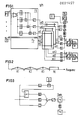
- a broadband switching system with a broadband switching arrangement BK, via the broadband signal sources P1 ... Pp, which may be given in particular by television program sources, with broadband signal receiving subscribers T1. ..Tt are connectable; These subscribers may, for example, each form an apartment connection, to / from which there may be a plurality of communication options in the manner explained at the beginning.
- Angle-modulated signals are transmitted via the broadband switching arrangement BK with the broadband signals, which are preferably given by TV signals, after which several such signals are frequency-multiplexed via one Optical fibers AL1 ... ALt can be transmitted to subscriber T1 ... Tt.
- the individual broadband signal sources P1 ... Pp are connected via appropriate modulation circuits F1 ... Fp to inputs e11, e12, e13; ...; ep1, ep2, ep3 of the broadband switching arrangement BK connected to the subscriber-specific outputs a11, a12, a13; ...; at1, at2, at3 the subscribers T1 ... Tt are connected;
- the individual input lines e11, e12, e13; ...; ep1, ep2, ep3 can be connected to the output lines a11, a12, a13; ...; at1, at2, at3 via crosspoint switches (not shown in the drawing).
- the crosspoint switches can be (e.g.
- ECL logic elements e.g. be formed by AND gates, for example of type 10 104 and / or by NOR gates, for example of type 10 102; they can also be combined into several monolithically integrated on a chip.
- the broadband switching arrangement BK Via the broadband switching arrangement BK, its subscriber-specific outputs are connected in each case in subscriber-specific (preferably via subscriber return channels, as mentioned at the beginning) specific frequency channels of a frequency division multiplex system to a desired input of the broadband coupling arrangement that is desired for each signal source.
- subscriber-specific preferably via subscriber return channels, as mentioned at the beginning
- specific frequency channels of a frequency division multiplex system to a desired input of the broadband coupling arrangement that is desired for each signal source.
- Fig.2 Such frequency channels are designated K1, K2, K3; TK denotes another area in which narrowband frequency channels can be accommodated, as will be explained in more detail below becomes.
- the three broadband channels K1, K2, K3 can, for example, have center frequencies of approximately 20, 48, 76 MHz with channel widths of approximately 28 MHz; the range TK could, for example, range from approximately 20 to 110 MHz and contain, for example, 20 channels with channel widths of approximately 1 MHz.
- a subscriber T1 ... Tt can use the crosspoint switches in question with the individual signal source-specific inputs e11, e12, e13; ...; ep1, ep2, ep3 (or e1 ... ep) of the broadband switching arrangement BK, wherein a subscriber can possibly also be connected to the same broadband signal source P1 ... Pp in several frequency channels.
- the broadband switching arrangement BK has frequency channel-specific coupling levels KE1, KE2, KE3, and the angle-modulated signals from the individual broadband signal sources P1 ... Pp are used in one of the number of signals T1 ... Tt which can be simultaneously connected to one and the same subscriber signal sources P1 ... Pp corresponding plurality of frequency channels K1 ... K3 (in Fig.2) of at least this frequency channels (K1 ... K3) comprising F r equenzmulti- plexsystems (Fig.2) signal source individual input e11, e12, e13 ; ...; ep1, ep2, ep3 of the individual frequency channel-specific coupling levels KE1 ... KE3 of the broadband coupling arrangement.
- the other fan-out circuits .... Fp can also be designed in a corresponding manner.
- the fan-out circuits F1 ... Fp ensure that each broadband signal emitted by a signal source P1 ... Pp in each of the frequency channels K1, K2, K3 is connected to an input e11, e12, e13; ...; ep1 , ep2, ep3 of the broadband switching arrangement BK is available and, accordingly, via the coupling point switches in question to the individual subscriber-specific outputs a11, a12, a13; ...; at1, at2, at3 and further in the frequency multiplex via the optical waveguide (AL) leading to the respective subscriber (T) to the individual subscribers T1 ... Tt.
- the above-mentioned subscriber-specific outputs are in each case connected downstream of filters which suppress harmonics and are connected on the output side in each case individually for subscribers.
- the subscriber-specific output lines at ... at can additionally be used to narrowband signal sources, in particular Sound program sources, so that these sound program sources, like the program source Pz shown in FIG. 1, in additional narrowband frequency channels of the frequency division multiplex system (see FIG. 2) are constantly connected to the optical fiber AL1 ... leading to the respective subscriber T1 ... Tt. ALt are connected;
- additional broadband signal sources, in particular TV program sources, in additional frequency channels of the frequency division multiplex system can also be connected in a corresponding manner to the optical fibers AL1 ... ALt leading to the subscribers T1 ... Tt.
- a frequency-modulated voltage-controlled oscillator VCO (or a receiver which receives the program broadcast by an FM radio transmitter (but not yet demodulated) is followed by a frequency booster circuit which modulates the frequency deviation may make about 1 to 2 orders of magnitude larger than the maximum modulation frequency.
- the signal which is frequency-modulated with the sound program and which occurs on line h can be converted in a known manner to an intermediate frequency, which may be approximately 10 MHz, for example, after which the converted signal is limited so that you get a very high harmonic signal.
- a harmonic is then forwarded by means of a bandpass filter, the frequency of which is greater than the intermediate frequency by approximately 1 to 2 orders of magnitude and the frequency deviation of which is thus also approximately 1 to 2 orders of magnitude (powers of ten) greater than before.
- a high signal / noise ratio is achieved at the receiving end when the electrical / opto-converter E / 0 is driven with a still low sound signal level , which enables simultaneous application of a correspondingly large number of further sound program signals to the electrical / opto-converter E / 0.
- the signals which have come to the respective subscriber T via the respective optical waveguide AL1,... ALt can be sent to the subscriber of a broadband communication network, as mentioned at the beginning, after implementation in an opto / electrical converter 0 / E on a housing unit individually provided for video and radio signals to be used and to one or more connecting sockets leading coaxial line to the respective receiver are transmitted, as is already described in principle elsewhere (DE-P 29 34 358.6).
- a conversion circuit as shown in FIG. 3, must be provided at the receiver for adaptation to conventional receiving devices.
- Such a conversion circuit can filter out one of the three channels K1, K2, K3 (in FIG.
- the video signals can also be reacted into the VHF-position and the receiver are supplied in a form suitable receiver an RF input.
- Broadband signals transmitted in additional frequency channels of the frequency division multiplex system according to FIG. 2, for example at center frequencies of approximately 124, 152, 180, 208, 236 MHz, can be filtered out in the converter circuit according to FIG. 3 by means of a corresponding high pass filter and then, for example, by means of an intermediate frequency converter be converted into a frequency position corresponding to the frequency channel K3 (in FIG. 3) and then supplied to the demodulator Dem instead of the broadband signal transmitted in the frequency channel K3 via the filter belonging to this channel.
Landscapes
- Engineering & Computer Science (AREA)
- Multimedia (AREA)
- Signal Processing (AREA)
- Computer Networks & Wireless Communication (AREA)
- Two-Way Televisions, Distribution Of Moving Picture Or The Like (AREA)
- Television Systems (AREA)
- Use Of Switch Circuits For Exchanges And Methods Of Control Of Multiplex Exchanges (AREA)
Applications Claiming Priority (2)
| Application Number | Priority Date | Filing Date | Title |
|---|---|---|---|
| DE2951512 | 1979-12-20 | ||
| DE19792951512 DE2951512A1 (de) | 1979-12-20 | 1979-12-20 | Breitband-vermittlungssystem |
Publications (2)
| Publication Number | Publication Date |
|---|---|
| EP0031457A2 true EP0031457A2 (fr) | 1981-07-08 |
| EP0031457A3 EP0031457A3 (fr) | 1981-07-15 |
Family
ID=6089128
Family Applications (1)
| Application Number | Title | Priority Date | Filing Date |
|---|---|---|---|
| EP80107320A Withdrawn EP0031457A3 (fr) | 1979-12-20 | 1980-11-24 | Système de commutation à large bande |
Country Status (4)
| Country | Link |
|---|---|
| US (1) | US4382266A (fr) |
| EP (1) | EP0031457A3 (fr) |
| JP (1) | JPS5694865A (fr) |
| DE (1) | DE2951512A1 (fr) |
Cited By (2)
| Publication number | Priority date | Publication date | Assignee | Title |
|---|---|---|---|---|
| EP0118161A1 (fr) * | 1983-03-07 | 1984-09-12 | ITT Nederland RSCE B.V. | Système de commutation |
| EP0167850A3 (en) * | 1984-06-11 | 1988-09-28 | Sumitomo Electric Industries Limited | Signal transmission system and method |
Families Citing this family (39)
| Publication number | Priority date | Publication date | Assignee | Title |
|---|---|---|---|---|
| DE3109470C2 (de) * | 1981-03-12 | 1983-09-29 | Siemens AG, 1000 Berlin und 8000 München | Breitband-Vermittlungssystem |
| NL8103064A (nl) * | 1981-06-25 | 1983-01-17 | Philips Nv | Gemeenschappelijke antenne-inrichting voor de ontvangst en distributie van tv- en digitale audiosignalen. |
| DE3138473A1 (de) * | 1981-09-26 | 1983-05-26 | AEG-Telefunken Nachrichtentechnik GmbH, 7150 Backnang | Dienstintegriertes nachrichtenuebertragungs- und vermittlungsnetz fuer bild, ton und daten |
| NL8203600A (nl) * | 1982-09-17 | 1984-04-16 | Philips Nv | Hoofdeinde en ontvanger voor een signaaldistributiesysteem. |
| JP2815853B2 (ja) * | 1984-06-25 | 1998-10-27 | 株式会社東芝 | 信号選択方式 |
| CA1256606A (fr) * | 1984-06-25 | 1989-06-27 | Taro Shibagaki | Systeme de transmission d'informations |
| DE3613051C2 (de) * | 1986-04-17 | 1994-09-08 | Siemens Ag | Koppelnetzbaustein für optische Signale |
| US4789980A (en) * | 1986-08-18 | 1988-12-06 | American Telephone & Telegraph Company, At&T Bell Laboratories | Switching techniques for FDM communication systems |
| US4858011A (en) * | 1988-04-04 | 1989-08-15 | Jackson Richard A | Video switcher system with modular architecture |
| JPH0286384A (ja) * | 1988-09-22 | 1990-03-27 | Pioneer Electron Corp | 動画像情報サービスシステム及び該システム用ヘッドエンド装置 |
| DE4019225A1 (de) * | 1990-06-15 | 1991-12-19 | Standard Elektrik Lorenz Ag | Optisches schaltelement |
| DE4326570B4 (de) * | 1993-08-07 | 2005-09-08 | Robert Bosch Gmbh | Verfahren zum Schalten und/oder Verteilen von elektrischen Bildsignalen in Übertragungssystemen |
| NL9401262A (nl) * | 1994-08-01 | 1996-03-01 | Sony Telecom Europ Nv | Systeem voor telecommunicatie. |
| US7142809B1 (en) * | 2001-02-27 | 2006-11-28 | The Directv Group, Inc. | Device and method to locally fill gaps in spotbeam satellite systems with frequency re-use |
| US20020154055A1 (en) * | 2001-04-18 | 2002-10-24 | Robert Davis | LAN based satellite antenna/satellite multiswitch |
| US7954127B2 (en) * | 2002-09-25 | 2011-05-31 | The Directv Group, Inc. | Direct broadcast signal distribution methods |
| US20040184746A1 (en) * | 2003-03-17 | 2004-09-23 | Chang Chin L. | Fiber optic connector extension for transmission of digital video data |
| US7958531B2 (en) | 2005-04-01 | 2011-06-07 | The Directv Group, Inc. | Automatic level control for incoming signals of different signal strengths |
| US7950038B2 (en) * | 2005-04-01 | 2011-05-24 | The Directv Group, Inc. | Transponder tuning and mapping |
| US8024759B2 (en) * | 2005-04-01 | 2011-09-20 | The Directv Group, Inc. | Backwards-compatible frequency translation module for satellite video delivery |
| US7945932B2 (en) * | 2005-04-01 | 2011-05-17 | The Directv Group, Inc. | Narrow bandwidth signal delivery system |
| US7987486B2 (en) * | 2005-04-01 | 2011-07-26 | The Directv Group, Inc. | System architecture for control and signal distribution on coaxial cable |
| US8621525B2 (en) * | 2005-04-01 | 2013-12-31 | The Directv Group, Inc. | Signal injection via power supply |
| US7900230B2 (en) * | 2005-04-01 | 2011-03-01 | The Directv Group, Inc. | Intelligent two-way switching network |
| US8549565B2 (en) * | 2005-04-01 | 2013-10-01 | The Directv Group, Inc. | Power balancing signal combiner |
| US20080016535A1 (en) * | 2005-09-02 | 2008-01-17 | The Directv Group, Inc. | Frequency shift key control in video delivery systems |
| US8789115B2 (en) * | 2005-09-02 | 2014-07-22 | The Directv Group, Inc. | Frequency translation module discovery and configuration |
| US7937732B2 (en) * | 2005-09-02 | 2011-05-03 | The Directv Group, Inc. | Network fraud prevention via registration and verification |
| US7991348B2 (en) | 2005-10-12 | 2011-08-02 | The Directv Group, Inc. | Triple band combining approach to satellite signal distribution |
| US8019275B2 (en) * | 2005-10-12 | 2011-09-13 | The Directv Group, Inc. | Band upconverter approach to KA/KU signal distribution |
| US20070089142A1 (en) * | 2005-10-14 | 2007-04-19 | John Norin | Band converter approach to Ka/Ku signal distribution |
| CN101502116A (zh) * | 2006-06-09 | 2009-08-05 | 直视集团公司 | 用于各种格式位流的呈现模式 |
| WO2007149403A2 (fr) * | 2006-06-16 | 2007-12-27 | The Directv Group, Inc. | Commande multimédia de stockage numérique et indexage de données de commande |
| US8719875B2 (en) | 2006-11-06 | 2014-05-06 | The Directv Group, Inc. | Satellite television IP bitstream generator receiving unit |
| US8712318B2 (en) | 2007-05-29 | 2014-04-29 | The Directv Group, Inc. | Integrated multi-sat LNB and frequency translation module |
| US8238813B1 (en) | 2007-08-20 | 2012-08-07 | The Directv Group, Inc. | Computationally efficient design for broadcast satellite single wire and/or direct demod interface |
| US9942618B2 (en) | 2007-10-31 | 2018-04-10 | The Directv Group, Inc. | SMATV headend using IP transport stream input and method for operating the same |
| BRPI1006912A2 (pt) | 2009-01-06 | 2016-02-16 | Directv Group Inc | estimação de deriva de frequência para unidade externa de baixo custo |
| WO2020204849A1 (fr) * | 2019-04-05 | 2020-10-08 | Ozyegin Universitesi | Système de transmission optique de données pour nageurs |
Family Cites Families (7)
| Publication number | Priority date | Publication date | Assignee | Title |
|---|---|---|---|---|
| US2854506A (en) * | 1955-06-15 | 1958-09-30 | Itt | Television signal distribution system |
| GB1114717A (en) * | 1964-05-29 | 1968-05-22 | Tokyo Shibaura Electric Co | Television sound broadcasting systems |
| US4064460A (en) * | 1974-03-16 | 1977-12-20 | Communications Patents Limited | Coaxial wired broadcasting system with tone responsive program selectors |
| GB1480749A (en) | 1974-03-16 | 1977-07-20 | Communications Patents Ltd | Wired broadcasting systems |
| DE2421002C3 (de) * | 1974-04-30 | 1980-07-03 | Siemens Ag, 1000 Berlin Und 8000 Muenchen | Nachrichtenvermittlungssystem |
| DE2828662C2 (de) | 1978-06-29 | 1980-02-28 | Siemens Ag, 1000 Berlin Und 8000 Muenchen | Schaltungsanordnung zum wahlweisen Durchschalten oder Sperren von Signalen hoher Bandbreite |
| DE2922418C2 (de) * | 1979-06-01 | 1981-12-03 | Licentia Patent-Verwaltungs-Gmbh, 6000 Frankfurt | Dienstintegriertes Nachrichtenübertragungs- und Vermittlungssystem für Ton, Bild und Daten |
-
1979
- 1979-12-20 DE DE19792951512 patent/DE2951512A1/de not_active Withdrawn
-
1980
- 1980-11-05 US US06/204,209 patent/US4382266A/en not_active Expired - Lifetime
- 1980-11-24 EP EP80107320A patent/EP0031457A3/fr not_active Withdrawn
- 1980-11-27 JP JP16598980A patent/JPS5694865A/ja active Pending
Cited By (2)
| Publication number | Priority date | Publication date | Assignee | Title |
|---|---|---|---|---|
| EP0118161A1 (fr) * | 1983-03-07 | 1984-09-12 | ITT Nederland RSCE B.V. | Système de commutation |
| EP0167850A3 (en) * | 1984-06-11 | 1988-09-28 | Sumitomo Electric Industries Limited | Signal transmission system and method |
Also Published As
| Publication number | Publication date |
|---|---|
| DE2951512A1 (de) | 1981-07-02 |
| JPS5694865A (en) | 1981-07-31 |
| EP0031457A3 (fr) | 1981-07-15 |
| US4382266A (en) | 1983-05-03 |
Similar Documents
| Publication | Publication Date | Title |
|---|---|---|
| DE2951512A1 (de) | Breitband-vermittlungssystem | |
| DE69017135T2 (de) | Hybrides Netzwerk. | |
| DE2922418C2 (de) | Dienstintegriertes Nachrichtenübertragungs- und Vermittlungssystem für Ton, Bild und Daten | |
| EP0151454B1 (fr) | Branchement d'abonné dans un système intégré à large bande | |
| DE69125314T2 (de) | Optisches Übertragungssystem und -verfahren | |
| DE3586573T2 (de) | Signaluebertragungssystem und verfahren. | |
| EP0028416B1 (fr) | Système de commutation à large bande | |
| CH661393A5 (de) | Gemeinschaftsantennenanordnung zum empfang und zur verteilung von fernseh- und digitalen audiosignalen. | |
| EP0024618B1 (fr) | Système de télécommunications à large bande | |
| EP0380945A2 (fr) | Système optique de transmission de communications à large bande, en particulier dans la région de branchement d'abonnés | |
| EP0028415B1 (fr) | Dispositif de couplage à large bande | |
| DE3632047C2 (de) | Optisches Nachrichtenübertragungssystem für Schmalband- und Breitband-Nachrichtensignale | |
| EP0031014B1 (fr) | Système de télécommunications | |
| DE3403206A1 (de) | Lichtwellenleiter-verteilnetz fuer fernseh- und tonprogramme | |
| DE2316166B2 (de) | Gemeinschaftsantennenanlage mit Alarmgebern für die einzelnen Teilnehmer | |
| DE3784643T2 (de) | Funksenderempfaengersystem zur erhoehung oder zur verringerung der uebertragungskanaele. | |
| DE2510865C3 (de) | Drahtfunksystem mit wenigstens einer an mehrere Programmquellen angeschlossenen Vermittlungsstelle | |
| EP0060318B1 (fr) | Système de commutation à large bande | |
| EP0144076B1 (fr) | Réseau de transmission numérique à intégration de services | |
| EP0031458A2 (fr) | Système de transmission à guides d'ondes de lumière et à multiplex à fréquence | |
| DE1912791C3 (de) | Langstrecke nrichtf unkanlage | |
| EP0651576B1 (fr) | Réseau de distribution de radio diffusion et télévision | |
| DE2548280C3 (de) | Vermittlungsanordnung nach dem Vierdraht-Trägerfrequenzprinzip | |
| DE69614072T2 (de) | Kabelnetzwerksystem für Videoverteilung und bidirektionale Datenübertragung, mit Freqenzumsetzung im Rückkanal | |
| DE4000859C2 (fr) |
Legal Events
| Date | Code | Title | Description |
|---|---|---|---|
| PUAI | Public reference made under article 153(3) epc to a published international application that has entered the european phase |
Free format text: ORIGINAL CODE: 0009012 |
|
| PUAL | Search report despatched |
Free format text: ORIGINAL CODE: 0009013 |
|
| AK | Designated contracting states |
Designated state(s): AT BE CH DE FR GB IT NL SE |
|
| AK | Designated contracting states |
Designated state(s): AT BE CH DE FR GB IT NL SE |
|
| 17P | Request for examination filed |
Effective date: 19811028 |
|
| STAA | Information on the status of an ep patent application or granted ep patent |
Free format text: STATUS: THE APPLICATION IS DEEMED TO BE WITHDRAWN |
|
| 18D | Application deemed to be withdrawn |
Effective date: 19830510 |
|
| RIN1 | Information on inventor provided before grant (corrected) |
Inventor name: PANZER, KLAUS, DR. ING. |