EP0031476A2 - Contrôleur de température comprenant un disque bimétallique à déclic - Google Patents
Contrôleur de température comprenant un disque bimétallique à déclic Download PDFInfo
- Publication number
- EP0031476A2 EP0031476A2 EP80107539A EP80107539A EP0031476A2 EP 0031476 A2 EP0031476 A2 EP 0031476A2 EP 80107539 A EP80107539 A EP 80107539A EP 80107539 A EP80107539 A EP 80107539A EP 0031476 A2 EP0031476 A2 EP 0031476A2
- Authority
- EP
- European Patent Office
- Prior art keywords
- housing
- snap
- temperature monitor
- temperature
- monitor according
- Prior art date
- Legal status (The legal status is an assumption and is not a legal conclusion. Google has not performed a legal analysis and makes no representation as to the accuracy of the status listed.)
- Granted
Links
Images


Classifications
-
- G—PHYSICS
- G01—MEASURING; TESTING
- G01K—MEASURING TEMPERATURE; MEASURING QUANTITY OF HEAT; THERMALLY-SENSITIVE ELEMENTS NOT OTHERWISE PROVIDED FOR
- G01K5/00—Measuring temperature based on the expansion or contraction of a material
- G01K5/48—Measuring temperature based on the expansion or contraction of a material the material being a solid
- G01K5/56—Measuring temperature based on the expansion or contraction of a material the material being a solid constrained so that expansion or contraction causes a deformation of the solid
- G01K5/62—Measuring temperature based on the expansion or contraction of a material the material being a solid constrained so that expansion or contraction causes a deformation of the solid the solid body being formed of compounded strips or plates, e.g. bimetallic strip
- G01K5/70—Measuring temperature based on the expansion or contraction of a material the material being a solid constrained so that expansion or contraction causes a deformation of the solid the solid body being formed of compounded strips or plates, e.g. bimetallic strip specially adapted for indicating or recording
Definitions
- the invention relates to a temperature monitor with a bimetallic snap disk.
- thermobimetal snap disks are characterized in that their temperature changes suddenly when the temperature changes, when an upper snap temperature T OS which is characteristic of the disk is exceeded or a lower snap temperature T US which is also characteristic of the disk is undershot.
- the curvature of the snap disc changes continuously until the direction of curvature snaps.
- the curvature height that is reached immediately before the snap is also characteristic of the pane is referred to as the snap height h S.
- the curvature height is 2 h s .
- a temperature monitor of the simplest possible design is of interest, in which subsequent temperature changes that have led to snap events can be read off immediately.
- a temperature monitor would be particularly useful, for example, for monitoring frozen or frozen food if it could be added to the refrigerated goods and would not reliably indicate inadmissible heating, i.e. an interruption in the freezer or freezer chain, if the frozen or Frozen food has been brought back to low temperature following the heating.
- the object of the invention is to design a temperature monitor with a bimetallic snap disk in such a way that one or possibly several temperature changes that have caused the snap disk to snap can be reliably read directly on the temperature monitor even after the snap disk has been snapped again.
- This object is achieved in accordance with the invention with a temperature monitor of the type mentioned at the outset in that, by at least snapping the snap disc, a rotation of an indicating element located in a common housing with the snap disc can be triggered.
- an embodiment of the temperature monitor according to the invention in which successive, same-directional, stepwise rotations of the display element can be triggered by successive snapping processes of the snap disk, is particularly favorable because of its diverse possible uses.
- temperature changes from frozen or frozen food can be read over several snap cycles at the respective end position of the display element.
- the housing of the temperature monitor can be opened.
- the snap disk can preferably itself be rotatably arranged in the housing and provided with markings and thus itself form the display element.
- a preferred embodiment of such a temperature monitor which is preferred because of its simple structure, is designed in such a way that the snap disk is provided with projections at two mutually opposite locations on its circumference, one of these projections being guided in a flat, annular guide slot and the other projection being substantially perpendicular to the Direction of rotation engages teeth, that the snap disc can be pretensioned for rotation by means of a torsion spring attached to the housing and that the snap disc and teeth are matched to one another such that when the snap disc is snapped, the projection engaging in the teeth is lifted over the tooth that is inhibiting it and after the corresponding rotation of the snap disc strikes the next tooth.
- the housing can advantageously consist of a base part and a cover part, the guide slot in the interior of the housing run between these two parts and the teeth alternate from the base part and the cover part.
- the housing consists of two essentially identical parts, between which an annular part is inserted, which keeps the guide slot between the two housing parts free and is also provided with the teeth. Both housing parts can advantageously be held together by a crimp ring.
- an outer housing made of preferably transparent plastic can be provided.
- the snap disk and display element can also be separate parts.
- the snap disc can be fixed in the housing and act on a rotatable display element that can be pretensioned for rotation by means of a torsion spring in such a way that when the snap disc is snapped over an obstacle that inhibits its rotation is lifted away.
- the curvature height h is plotted on the ordinate and the temperature T on the abscissa. If, for example, the temperature is changed from T 1 to T 2 , the curvature height initially decreases continuously from the value h 1 until the value h S is reached at the upper snap temperature T OS (point a). From there, the disk snaps into position b, reversing its direction of curvature, and the curvature height assumes the value -2h S and changes continuously to -h 2 in the later course.
- the snap disk correspondingly passes through positions 2, b, c, d, 1.
- a maximum snap stroke of 3 h S is thus available for use.
- the characteristic values T OS , T US and h S can be adapt to the respective requirements within wide limits by appropriate selection of material and dimensions of the snap disks.
- FIGS. 2 to 4 An exemplary embodiment of the temperature monitor according to the invention, in which the snap disk also serves as a display element, is shown in FIGS. 2 to 4, specifically in FIG. 2 in a top view with the housing cover lifted off, and in FIG. 3 in cross section through the middle of the housing parallel to the direction A. 4 finally shows an interior view of the housing in the direction A.
- the housing consists of a base part 11 and a cover part 12. Between the two, a snap disk 13 provided with a central hole is rotatably mounted about a pin 14 provided on the cover part 12.
- the pin 14 also serves to hold a torsion spring 15 in the housing, the free end of which is fastened in an opening of the snap disk 13.
- the snap disc 13 is provided at one point on its circumference with a nose-shaped projection 16 and on the opposite side with a flat extension 17.
- This approach 17 serves to guide the snap disk 13 in an annular slot 18 formed between the base part 11 and the cover part 12 and running along part of the housing inner wall meandering slit 1-9 provided.
- the meandering course is effected by teeth 20 to 24, which alternate from the bottom part 11 and from the cover part 12 of the housing.
- Ball-shaped supports 25 and 26 are used for the additional storage of the snap disk 13.
- five sector-shaped fields 27 to 31 are marked in different colors, which when the snap disk 13 is rotated one after the other passes under a likewise sector-shaped window 32 in the cover part 12 and is observed through it can.
- a snap disc 13 will be selected, whose lower snap temperature T US at approximately -30 ° C and its upper snap temperature T OS at approximately -15 ° C.
- the height of the teeth 20 to 24 is to be coordinated with the snap path of the projection 16 in such a way that the projection is lifted over the tooth that is inhibiting it when it is snapped and held in place after the snap disk has been rotated from the following tooth until it snaps again.
- the snap disk 13 can then be pretensioned by means of the torsion spring 15 for the purpose of rotation in such a way that the nose-shaped projection 16 comes to rest in front of the tooth 20 in a clockwise direction and the color sector 27 appears under the window 32.
- the temperature monitor can be stored at room temperature for any length of time and added to the frozen food at any time if required.
- Das.Genosuse can then consist of plastic, which is transparent at least in the area of the window 32. Bottom part 11 and cover part 12 can then be welded tightly together, for example by means of ultrasound. If you want to use the temperature monitor several times, the housing must be able to be opened again so that the snap disk can be pretensioned again using the torsion spring. When closing the then. For example, housing made of metal or plastic must be ensured that a good seal is achieved so that foreign substances do not penetrate into the temperature monitor from the outside and can impair its functionality. In addition, security against unauthorized opening of the housing is advisable. For example, the housing can be sealed or the entire temperature monitor can be welded into a specially marked plastic film. Such a film can also serve to avoid undesired contacts between the housing material of the temperature monitor and the surrounding chilled goods. If necessary, you can also choose the housing material so that there are no adverse effects when in contact with the surrounding refrigerated goods.
- the side surfaces of these teeth can be chamfered so that the teeth taper towards their respective free ends.
- the side surfaces of the slot 18 used to guide the shoulder 17 can be designed similarly to the supports 25 and 26 instead of being spherically flat.
- the snap paths that is to say the height of the teeth 20 to 24, are shown greatly exaggerated in FIGS. 2 to 4 for reasons of clarity.
- the snap 16 has a snap path of approximately 1.5 mm to disposal.
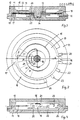
- FIGS. 5 to 7 A further advantageous embodiment of the temperature monitor according to the invention, in which the snap disk also serves as a display element, is shown in FIGS. 5 to 7, namely, FIG. 5 shows the temperature monitor in section, FIG. 6 shows the snap disk and the parts essential for its guidance in plan view and Fig. 7 shows a section through a toothed annular part.
- the inner housing of the temperature monitor consists of two essentially identical, lid-shaped parts 40 and 41, which differ only in that the part 40 additionally contains a window 42.
- An annular part 43 is arranged between the two parts 40 and 41, which both holds a guide slot 44 for a projection 45 of the snap disk 46 and is provided on the opposite side with teeth 47, into which another projection 48 of the snap disk 46 engages .
- the snap disk 46 is centered around one Baying of the housing parts 40 and 41 arranged pivot 49 and can be biased for rotation by means of a spring 50.
- the spring 50 is anchored in openings 51 and 52 of the housing parts 40 and 41 and engages on the projection 45 of the snap disk 46 guided in the guide slot 44.
- the snap disk 46 itself is provided with color markings 53 which, when the snap disk 46 is rotated, are successively visible in the window 42 and indicate the respective state of the temperature monitor.
- the housing parts 40 and 41 are held together by a crimp ring 54.
- an outer housing 55 made of transparent plastic is provided. The two parts of this housing 55 can be welded tightly to one another at the edge, for example by means of ultrasound.
- the parts 40, 41, 43 and 54 can advantageously be made of sheet metal.
- the temperature monitors according to the invention can also be used for temperature monitoring in other temperature ranges. Examples are p monitoring Lagertem e-temperature during the cold storage of chemicals, pharmaceuticals, vaccines and the like As already briefly indicated, the temperature monitor can also be used to monitor high temperatures, for example to check whether the sterilization temperature has actually been reached in the items to be sterilized. Bimetallic snap disks with corresponding characteristic values must then be selected for the different application purposes. The number of snap cycles that can be read on the temperature monitor can also be adapted to the specific needs.
Landscapes
- Physics & Mathematics (AREA)
- General Physics & Mathematics (AREA)
- Measuring Temperature Or Quantity Of Heat (AREA)
- Thermally Actuated Switches (AREA)
- Temperature-Responsive Valves (AREA)
Priority Applications (1)
| Application Number | Priority Date | Filing Date | Title |
|---|---|---|---|
| AT80107539T ATE18606T1 (de) | 1979-12-22 | 1980-12-03 | Temperaturwaechter mit einer thermobimetallschnappscheibe. |
Applications Claiming Priority (2)
| Application Number | Priority Date | Filing Date | Title |
|---|---|---|---|
| DE2952138 | 1979-12-22 | ||
| DE2952138A DE2952138C2 (de) | 1979-12-22 | 1979-12-22 | Temperaturwächter mit einer Thermobimetallschnappscheibe |
Publications (3)
| Publication Number | Publication Date |
|---|---|
| EP0031476A2 true EP0031476A2 (fr) | 1981-07-08 |
| EP0031476A3 EP0031476A3 (en) | 1983-06-08 |
| EP0031476B1 EP0031476B1 (fr) | 1986-03-12 |
Family
ID=6089524
Family Applications (1)
| Application Number | Title | Priority Date | Filing Date |
|---|---|---|---|
| EP80107539A Expired EP0031476B1 (fr) | 1979-12-22 | 1980-12-03 | Contrôleur de température comprenant un disque bimétallique à déclic |
Country Status (3)
| Country | Link |
|---|---|
| EP (1) | EP0031476B1 (fr) |
| AT (1) | ATE18606T1 (fr) |
| DE (1) | DE2952138C2 (fr) |
Cited By (3)
| Publication number | Priority date | Publication date | Assignee | Title |
|---|---|---|---|---|
| DE3834903A1 (de) * | 1988-10-13 | 1990-04-19 | Wanfried Druck Kalden Gmbh | Indikatorsystem zur anzeige von kritischen temperaturbereichen |
| WO1994016299A1 (fr) * | 1992-12-31 | 1994-07-21 | Symbiosis Corporation | Compteur de cycles de temperature |
| CN108597958A (zh) * | 2018-06-11 | 2018-09-28 | 佛山市高明欧电子制造有限公司 | 一种带一次性过热保护的可调式温控器 |
Family Cites Families (6)
| Publication number | Priority date | Publication date | Assignee | Title |
|---|---|---|---|---|
| US2966261A (en) * | 1958-07-25 | 1960-12-27 | James W Bradbury | Temperature sensing device |
| DE1786865U (de) * | 1959-01-29 | 1959-04-16 | Reese Technik Inh Ing Werner R | Elektrisches mehrzweck-geraet. |
| DE7531355U (de) * | 1975-10-03 | 1978-04-27 | Inter Control Hermann Koehler Elektrik Gmbh & Co Kg, 8500 Nuernberg | Rückstellbarer Temperaturbegrenzer |
| US4064827A (en) * | 1976-08-19 | 1977-12-27 | Telatemp Corporation | Temperature indicating device |
| DE2638416C3 (de) * | 1976-08-26 | 1981-03-19 | Fa. Wilhelm Giesen, 4010 Hilden | Anzeigevorrichtung, welche die Erreichung eines Temperaturwertes anzeigt |
| US4091763A (en) * | 1977-01-05 | 1978-05-30 | Therm-O-Disc Incorporated | Temperature indicator |
-
1979
- 1979-12-22 DE DE2952138A patent/DE2952138C2/de not_active Expired
-
1980
- 1980-12-03 AT AT80107539T patent/ATE18606T1/de not_active IP Right Cessation
- 1980-12-03 EP EP80107539A patent/EP0031476B1/fr not_active Expired
Cited By (4)
| Publication number | Priority date | Publication date | Assignee | Title |
|---|---|---|---|---|
| DE3834903A1 (de) * | 1988-10-13 | 1990-04-19 | Wanfried Druck Kalden Gmbh | Indikatorsystem zur anzeige von kritischen temperaturbereichen |
| WO1994016299A1 (fr) * | 1992-12-31 | 1994-07-21 | Symbiosis Corporation | Compteur de cycles de temperature |
| CN108597958A (zh) * | 2018-06-11 | 2018-09-28 | 佛山市高明欧电子制造有限公司 | 一种带一次性过热保护的可调式温控器 |
| CN108597958B (zh) * | 2018-06-11 | 2023-09-01 | 佛山市高明欧一电子制造有限公司 | 一种带一次性过热保护的可调式温控器 |
Also Published As
| Publication number | Publication date |
|---|---|
| DE2952138A1 (de) | 1981-07-02 |
| EP0031476A3 (en) | 1983-06-08 |
| ATE18606T1 (de) | 1986-03-15 |
| DE2952138C2 (de) | 1982-11-18 |
| EP0031476B1 (fr) | 1986-03-12 |
Similar Documents
| Publication | Publication Date | Title |
|---|---|---|
| DE68916737T2 (de) | Temperaturkontrolleinrichtung, die mindestens ein Memorygemisch-Element enthält. | |
| DE2649934B2 (de) | Luftdruckregeleinrichtung | |
| DE2732083C2 (de) | Magnetbandkassette | |
| EP0031476B1 (fr) | Contrôleur de température comprenant un disque bimétallique à déclic | |
| DE69914575T2 (de) | Drehsensor | |
| DE2419504C3 (de) | Kunststoffgehäuse für einen Kaltleiter oder für eine Kaltleiterkombination | |
| DE603754C (de) | Wechselschalter fuer Telephonvermittlungsstellen u. dgl. | |
| DE2732326C2 (de) | Clip zum Unterbrechen von Leitungsbahnen | |
| DE6948279U (de) | Magnetband-kassette. | |
| DE4430822C1 (de) | Schraubverschluß für einen Dampfbehälter | |
| EP0191387A1 (fr) | Verrouillage à clapet frontal de cassettes à bande magnétique, notamment cassettes à bande vidéo | |
| DE69317225T2 (de) | Elektronische Vorrichtung zur Aufnahme einer Kassette | |
| DE68908494T2 (de) | Passiv-Strahlungsdetektor. | |
| DE4111077C2 (fr) | ||
| DE2419537B2 (de) | Filmlängen-Zähler für eine Filmkamera | |
| DE3018284C2 (de) | Thermomagnetisch betätigter Schalter | |
| DE3432835A1 (de) | Vorrichtung zum selbsttaetigen verstellen, insbesondere zum oeffnen und schliessen von vorzugsweise schwenkbar gelagerten elementen | |
| DE2707082A1 (de) | Digitale optische anzeigeeinrichtung | |
| DE60020458T2 (de) | Plattenkassette mit scheibenschutzvorrichtung | |
| DE2444329C2 (de) | Elektrischer Installationsschalter | |
| EP1295166A2 (fr) | Unite frontale d'appareil electrique | |
| EP0853757B1 (fr) | Dispositif de detection et de mise en garde contre le rayonnement solaire provoquant des lesions cutanees | |
| WO2006024408A1 (fr) | Dispositif de surveillance durable d'un rechauffement nuisible | |
| DE868108C (de) | Vorrichtung fuer Aufnahmekameras zur Anzeige des verwendeten Aufnahmematerials | |
| DE4109449C2 (de) | Analog anzeigendes Vielfach-Meßgerät mit einer Skalenwechselvorrichtung |
Legal Events
| Date | Code | Title | Description |
|---|---|---|---|
| PUAI | Public reference made under article 153(3) epc to a published international application that has entered the european phase |
Free format text: ORIGINAL CODE: 0009012 |
|
| AK | Designated contracting states |
Designated state(s): AT BE CH DE FR GB IT NL |
|
| 17P | Request for examination filed |
Effective date: 19811026 |
|
| PUAL | Search report despatched |
Free format text: ORIGINAL CODE: 0009013 |
|
| AK | Designated contracting states |
Designated state(s): AT BE CH DE FR GB IT LI NL |
|
| ITF | It: translation for a ep patent filed | ||
| GRAA | (expected) grant |
Free format text: ORIGINAL CODE: 0009210 |
|
| AK | Designated contracting states |
Kind code of ref document: B1 Designated state(s): AT BE CH FR GB IT LI NL |
|
| REF | Corresponds to: |
Ref document number: 18606 Country of ref document: AT Date of ref document: 19860315 Kind code of ref document: T |
|
| ET | Fr: translation filed | ||
| PLBE | No opposition filed within time limit |
Free format text: ORIGINAL CODE: 0009261 |
|
| STAA | Information on the status of an ep patent application or granted ep patent |
Free format text: STATUS: NO OPPOSITION FILED WITHIN TIME LIMIT |
|
| 26N | No opposition filed | ||
| PGFP | Annual fee paid to national office [announced via postgrant information from national office to epo] |
Ref country code: GB Payment date: 19901108 Year of fee payment: 11 |
|
| PGFP | Annual fee paid to national office [announced via postgrant information from national office to epo] |
Ref country code: AT Payment date: 19901128 Year of fee payment: 11 |
|
| PGFP | Annual fee paid to national office [announced via postgrant information from national office to epo] |
Ref country code: BE Payment date: 19901205 Year of fee payment: 11 |
|
| PGFP | Annual fee paid to national office [announced via postgrant information from national office to epo] |
Ref country code: FR Payment date: 19901228 Year of fee payment: 11 |
|
| ITTA | It: last paid annual fee | ||
| PGFP | Annual fee paid to national office [announced via postgrant information from national office to epo] |
Ref country code: NL Payment date: 19901231 Year of fee payment: 11 |
|
| PGFP | Annual fee paid to national office [announced via postgrant information from national office to epo] |
Ref country code: CH Payment date: 19910214 Year of fee payment: 11 |
|
| PG25 | Lapsed in a contracting state [announced via postgrant information from national office to epo] |
Ref country code: GB Effective date: 19911203 Ref country code: AT Effective date: 19911203 |
|
| PG25 | Lapsed in a contracting state [announced via postgrant information from national office to epo] |
Ref country code: LI Effective date: 19911231 Ref country code: CH Effective date: 19911231 Ref country code: BE Effective date: 19911231 |
|
| BERE | Be: lapsed |
Owner name: VACUUMSCHMELZE G.M.B.H. Effective date: 19911231 |
|
| PG25 | Lapsed in a contracting state [announced via postgrant information from national office to epo] |
Ref country code: NL Effective date: 19920701 |
|
| GBPC | Gb: european patent ceased through non-payment of renewal fee | ||
| NLV4 | Nl: lapsed or anulled due to non-payment of the annual fee | ||
| PG25 | Lapsed in a contracting state [announced via postgrant information from national office to epo] |
Ref country code: FR Effective date: 19920831 |
|
| REG | Reference to a national code |
Ref country code: CH Ref legal event code: PL |
|
| REG | Reference to a national code |
Ref country code: FR Ref legal event code: ST |