EP0031611A2 - Procédé et appareil pour joindre, au large, des tronçons de tuyaux à proximité de la surface de l'eau - Google Patents
Procédé et appareil pour joindre, au large, des tronçons de tuyaux à proximité de la surface de l'eau Download PDFInfo
- Publication number
- EP0031611A2 EP0031611A2 EP80201156A EP80201156A EP0031611A2 EP 0031611 A2 EP0031611 A2 EP 0031611A2 EP 80201156 A EP80201156 A EP 80201156A EP 80201156 A EP80201156 A EP 80201156A EP 0031611 A2 EP0031611 A2 EP 0031611A2
- Authority
- EP
- European Patent Office
- Prior art keywords
- pipe
- pipe ends
- hinge
- hinge halves
- strings
- Prior art date
- Legal status (The legal status is an assumption and is not a legal conclusion. Google has not performed a legal analysis and makes no representation as to the accuracy of the status listed.)
- Granted
Links
- 238000000034 method Methods 0.000 title claims description 33
- XLYOFNOQVPJJNP-UHFFFAOYSA-N water Substances O XLYOFNOQVPJJNP-UHFFFAOYSA-N 0.000 title claims description 25
- 239000012530 fluid Substances 0.000 description 7
- 238000013459 approach Methods 0.000 description 4
- 230000008878 coupling Effects 0.000 description 4
- 238000010168 coupling process Methods 0.000 description 4
- 238000005859 coupling reaction Methods 0.000 description 4
- 238000009434 installation Methods 0.000 description 3
- 230000008569 process Effects 0.000 description 3
- 238000005452 bending Methods 0.000 description 2
- 238000007796 conventional method Methods 0.000 description 2
- 230000007246 mechanism Effects 0.000 description 2
- 238000012360 testing method Methods 0.000 description 2
- PEDCQBHIVMGVHV-UHFFFAOYSA-N Glycerine Chemical compound OCC(O)CO PEDCQBHIVMGVHV-UHFFFAOYSA-N 0.000 description 1
- 241000282887 Suidae Species 0.000 description 1
- 230000009471 action Effects 0.000 description 1
- 230000003213 activating effect Effects 0.000 description 1
- 230000008859 change Effects 0.000 description 1
- 238000010276 construction Methods 0.000 description 1
- 238000013461 design Methods 0.000 description 1
- 230000000694 effects Effects 0.000 description 1
- 238000007667 floating Methods 0.000 description 1
- 238000007689 inspection Methods 0.000 description 1
- 230000013011 mating Effects 0.000 description 1
- 238000002360 preparation method Methods 0.000 description 1
- 230000001681 protective effect Effects 0.000 description 1
- 238000007789 sealing Methods 0.000 description 1
Images

Classifications
-
- F—MECHANICAL ENGINEERING; LIGHTING; HEATING; WEAPONS; BLASTING
- F16—ENGINEERING ELEMENTS AND UNITS; GENERAL MEASURES FOR PRODUCING AND MAINTAINING EFFECTIVE FUNCTIONING OF MACHINES OR INSTALLATIONS; THERMAL INSULATION IN GENERAL
- F16L—PIPES; JOINTS OR FITTINGS FOR PIPES; SUPPORTS FOR PIPES, CABLES OR PROTECTIVE TUBING; MEANS FOR THERMAL INSULATION IN GENERAL
- F16L1/00—Laying or reclaiming pipes; Repairing or joining pipes on or under water
- F16L1/26—Repairing or joining pipes on or under water
Definitions
- the present invention relates to a method and apparatus for the offshore joining of two pipe strings at least near the surface of a water body, wherein part of each pipe string lies on the bottom of the water body during at least part of the time of joining.
- the joining of two long strings of pipe near the water surface includes the following cases: both string ends are initially on bottom and must be raised for joining; a previously laid string is initially on bottom and the other arriving string is floating, ready for joining; and a previously laid string is on bottom and the arriving string has been towed to location on bottom, but with the forward end near the surface, in a "nose up" fashion.
- the conventional method for joining two pipe strings near the water surface is to grip the pipe ends and align them based on a common horizontal pipe centre-line axis. With the string ends in this position a weld is made Q r a mechanical connector installed. In order to prevent the suspended portions of the pipe strings from buckling during this operation, these suspended portions must be supported in the overbend by a stinger, davits or by buoys and in the sagbend by maintaining tension on the string ends.
- the present invention provides a method and an apparatus for the offshore joining of two pipe strings wherein the above- mentioned problems do not occur.
- the method according to the invention for the offshore joining of two pipe strings at least near the surface of a water body, wherein part of each pipe string lies on the bottom of the water body during at least part of the time of joining comprises positioning adjacent ends of both pipe strings at least near the surface of the water body, hinging the adjacent pipe ends together, and lowering the hinged pipe ends to the bottom of the water body while simultaneously exerting tension on one of the pipe strings from a remote location.
- the invention includes a method for aligning two pipe ends by affixing the pipe ends with disconnected hinge halves each having a pivot axis exterior of the pipe ends, positioning the pipe ends at an angle to the horizontal and at about the same relative height such that the centre lines of the pipe ends cross a common point above the pipe ends and merging the pivot axes of the hinge halves below the pipe ends, rotatably connecting the hinge halves at the merged pivot axes, and ⁇ lowering the pipe ends to an aligned position.
- the apparatus according to the invention for aligning two pipe ends comprises disconnectable hinge halves which are rotatably attachable to the pipe ends, each of the hinge halves being so constructed that when attached to a pipe end, each hinge half has a pivot axis which is (a) exterior of the pipe end; (b) perpendicular to a plane containing the pipe end centre line and (c) at least close to a plane formed by the circumferential edge of the pipe end, the ' apparatus further comprising means for rotatably attaching the hinge halves at the pivot axes.
- pipe string ends 20 and 21 are suspended from the sea floor 22 and held in a "J" configuration, without overbend, while using tension to control the sagbend.
- Pipe string ends 20 and 21 extend through a moon pool 23 in a barge 24 and are suspended by a lift frame 25.
- the pipe string ends caibe joined with a lift frame on the side of a barge.
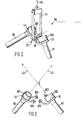
- a pipe joining hinge 30 for the joining operation is shown in Figure 2.
- Halves 31 and 32 of the hinge 30 are each rotated about the centre line of the pipe string ends 20 and 21.
- the hinge axis 33 is below and exterior of the pipe string ends 20 and 21, but supported vertically with a lever arm 34 so that hinge axis 33 remains horizontal, even during lowering.
- the two halves 31 and 32 of the hinge 30 may be pre-installed on the string ends 20 and 21 before the pipe strings are towed to location, and pin 35 can be inserted on site. Once the pin 35 is inserted and locked, the ends are closed and brought into complete alignment simply by lowering the hinge joint towards the sea floor 22 while simultaneously holding back tension on the opposite end of the new string.
- a mechanical connector may be latched and sealed as a direct result of the pivoting action associated with lowering the hinge to the sea floor.
- a connector may be separately installed or actuated at the sea floor, once the joint has been lowered.
- pipe plugs can be used to keep the pipe ends dry until the connector is in place. These plugs must be removed prior to locking the connector or pumped out of the pipeline afterwards. Once the connector is tight, parts of the hinge mechanism 30 can be detached and recovered for subsequent use, if desired.
- the pipeline is being constructed by the bottom-tow method where long (up to eight kilometres in length for example) strings of pipe are pre-fabricated and towed along the sea bed and positioned on the right-of-way simply by a tow vessel pulling on one end of the string.
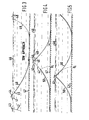
- the tow may be either one where the pipe remains essentially on bottom during tow or the method may involve suspending a long section of pipe under towing tension so that the pipe end is at or near the surface (see Figure 3).
- the first of the three major steps of this invention is, then, gross positioning.
- a new pipe string 40 is brought into alignment along the right-of-way approaching from the direction opposite to a previously installed pipe string 50.
- a tow vessel 41 picks up a cable 42 attached to the end of the previously installed pipe string 50, which cable 42 has been secured to a buoy 43 or tended by a support vessel (not shown).
- Cable 42 is of a strength and length dictated by the pipe characteristics and the water depth to permit raising the pipe under tension in a manner similar to that presently practised in abandoning and recovering pipelines from conventional lay barges.
- the two pipe strings 40 and 50 are now each connected to the winches 44 of vessel 41 by their lifting or towing cables 42 and 45.
- the new string 40 If the new string 40 has been towed on bottom, it is next raised to near the surface by the winch 44.
- the winch system is then utilized to apply tension to the cable 42 of the previously installed pipe string 50 and begin raising it also.
- the vessel 41 and the entire new pipe string 40)are moved in the direction of the previously installed pipe string 50.
- the point of reference is the original position (on bottom) of the previously installed pipe end (see Figure 4, reference point 0 i ).
- the second of the three major steps of this invention is, as mentioned, fine positioning of the pipe string ends.
- the vessel 41 is manoeuvered parallel to the right-of-way to assist in bringing the ends near to each other as the cables 42 and 45 are shortened.
- the suspended pipe strings 40 and 50 are in most cases tolerant of rather large excursions of the vessel 41 and of changes in the horizontal force component that controls pipe curvature. If the two lifting cables 42 and 45 are arranged to essentially touch each other (for instance by crossing anywhere between the pipe ends of pipe strings 40 and 50 and lifting sheaves), a plane is determined in space that includes the shortened cable segments 42 and 45 and the pipe ends.
- the third of the three major steps of this invention involves fixing of the ends of the pipe strings 40 and 50.
- a split hinge 30 By means of a split hinge 30 the two pipe ends are structurally joined through a pivot or hinge pin 35 so as to permit rotation about the pivot but only in the plane perpendicular to the pivot.
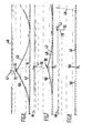
- the pipe ends are now suspended at an angle to the horizontal (see Figure 5), the change in angle and the relative position of the two ends is determined and predictable during the process of lowering the pipe to the water bottom 47.
- one cable may be disconnected, the pivot assembly 30 (and pipe strings 40 and 50) thenleing supported by a single cable 70 attached to the hinge 30.
- the required horizontal force components are maintained in each suspended pipe span through the hinge 30 and are equal and opposite.
- any necessary changes in pipe end fittings preferably are accomplished and the actual pipe connector (not shown) readied.
- the connection may be made on the surface through some form of swivel for example, or the connector may be one that is activated directly by the rotation of the pipe ends about the pivot 30 causing the connector halves (not shown) to be mated and latched as the pipeline 40-50 approaches the bottom 47.
- the hinge 30 may serve primarily to align and secure the ends of the pipe strings 40 and 50 on bottom 47 at a fixed alignment and relative position so that a pre-installed connector (not shown) may then be activated to accomplish the mechanical and fluid connections; in this latter case the hinge 30 preferably includes various latching members (not shown) to ensure such positioning.
- the next activities depend upon the type of connector 90 that is installed. If the connector 90 is of the surface-installed swivel type - or if it is of the self-energizing type - the surface vessel 41 may conduct or direct a test of the connection and then disconnect from the pipeline 40-50. If the connector 90 is of the independent type, the vessel 41 may cause the connector to activate, or the connection may be energized by other means. Again, after testing, the vessel 41 is released (see Figure 8). In either case, the second tow vessel 48 may now either release (and buoy off) cable 49 or it may remain on station to tend the cable 49 for installation of a further (not shown) pipe string.
- ends of the pipe strings 40 and 50 are lifted from the bottom 47 to the surface 46 of the water, so that initial connecting procedures may be carried out conveniently without the need of divers.under pressure or of submersible vehicles.
- the lifting is done by application of controlled tension in cables 42 and 45 combined with movement of the supporting vessel 41 so as to always maintain the desired horizontal and vertical components of this tension. This horizontal component restricts the curvature of the suspended pipeline span so as to prevent failure in bending as has been taught elsewhere and is well understood.
- the pipe-connecting means 100 and 101 were previously attached to the pipelines together with suitable fittings for establishing the mechanical alignment of the two pipe ends 40 and 50, here indicated as half hinge devices 31 and 32 preferably mounted to the pipe ends so as to permit rotation about the pipeline 40-50 without altering the tangential nature of the hinge pin holes shown as 102, 103 and 104, 105.
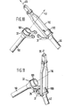
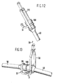
- a lifting or lowering frame 110 may be arranged to rotate about the axis of the pipeline in a manner similar to, but independent of the hinge half 31 or 32 ( Figure 12). Yet another configuration would attach the frame to the hinge pin axis ( Figure 2).
- This device is to maintain the attached cable 70 clear of the two connector halves 100 and 101 as they approach each other while the assembly is lowered beneath the surface. Supporting the vertical load by one cable 70 attached to the lowering frame 34, the second cable may be removed, leaving only the main lowering cable 70 attached to the entire assembly.
- the lifting and lowering device and the lifting and lowering cable may be pre-assembled.
- connector halves 100 and 101 In preparation for restoring the pipe 40-50 to the sea floor 47 and effecting a connection, several operations may be needed concerning connector halves 100 and 101: removal of any lift attachments; removal of protective caps; installation or inspection of temporary fluid sealing plugs or devices employed to prevent flooding of the pipelines during lowering; installation of connector seals, gaskets, activating devices, etc.
- Lowering of the assembly is accomplished by co-ordinating the movements of the support vessel 41 and its lowering cable 70 with those of the vessel 48 which is exerting a longitudinal force on the far end of one of the pipelines.
- the actual mechanical and fluid connections between pipe strings 40 and 50 may take place automatically or by command during lowering as controlled by rotational position about the hinge pin 35 or it maybe independent and. commanded and actuated after the assembly has been lowered to, or near, the bottom 47 ( Figure 13). In the latter case, some latching means (not shown) may be included to secure the pipe strings 40 and 50 from further rotation when the connector halves 100 and 101 are in proper alignment.
- An automatic or self-activating pipeline coupling may be included as a part of the apparatus when installing pipelines by this method.
- the coupling may include, firstly, an automatic guide and latching mechanism actuated by the rotation of the two pipes about the hinge with the latch position selected so as to ensure latching before the two pipelines are completely on bottom so that sufficient vertical movement is available to cause full engagement, and secondly, a fluid connection activated by external means.
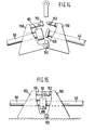
- pivot alignment frame 150 and latch with a socket 151 and engageable ball 152 shown in Figures 14 and 15 may also be useful in establishing a pipe connection by an independently activated coupling device.
- the pivot device 150 through a pivot 153 and separate latch 151-152, provides alignment and spacing for any independent coupling.
- the present invention includes the completion of the mechanical and fluid connection near or above the water level, with a suitable swivel included to permit the connected pipeline to be returned to the sea floor.
- This swivel has its axis perpendicular to the general pipeline alignment so that the two connected pipes may freely rotate about this axis as they are lowered, without affecting the connection.
- Pipe bends may be required on each side of the swivel. It is frequently a requirement of pipeline design that large radius (equivalent to 3 or 4 pipe diameters) bends be employed in order to assure free passage of scrapers or pigs during pipeline operations. For this reason, it may be necessary to supply specialized lifting links or frames in order to raise and to align the pipeline ends with the large bends attached. Alternatively, the pipe ends may be raised without bends or swivel halves and then joined by a prepared spool piece (bends and swivel as a unit) or by two girth welds or mechanical connections.
- the mechanical and fluid connection may be achieved by any of several means, including: a connector-swivel; a single mechanical connector, preferably in the horizontal run at one side of the built-in swivel; a girth weld; or two girth welds, or two mechanical connections, to install a pre-fabricated spool including bends and swivel, by joining in the near vertical pipe ends.
- a significant feature of using an eccentric hinge alignment procedure as set forth herein is that, upon lowering of the hinged pipe ends, a substantial bending lever is created to press the pipe ends together. This means not only that connectors requiring a large engagement force can be used, but more importantly that a connector which automatically latches when rotated into position can be employed.
Landscapes
- Engineering & Computer Science (AREA)
- General Engineering & Computer Science (AREA)
- Mechanical Engineering (AREA)
- Earth Drilling (AREA)
- Catching Or Destruction (AREA)
- Buildings Adapted To Withstand Abnormal External Influences (AREA)
- Supports For Pipes And Cables (AREA)
- Lining Or Joining Of Plastics Or The Like (AREA)
Applications Claiming Priority (2)
| Application Number | Priority Date | Filing Date | Title |
|---|---|---|---|
| US10682079A | 1979-12-26 | 1979-12-26 | |
| US106820 | 1979-12-26 |
Publications (3)
| Publication Number | Publication Date |
|---|---|
| EP0031611A2 true EP0031611A2 (fr) | 1981-07-08 |
| EP0031611A3 EP0031611A3 (en) | 1981-12-30 |
| EP0031611B1 EP0031611B1 (fr) | 1984-04-18 |
Family
ID=22313441
Family Applications (1)
| Application Number | Title | Priority Date | Filing Date |
|---|---|---|---|
| EP80201156A Expired EP0031611B1 (fr) | 1979-12-26 | 1980-12-04 | Procédé et appareil pour joindre, au large, des tronçons de tuyaux à proximité de la surface de l'eau |
Country Status (7)
| Country | Link |
|---|---|
| EP (1) | EP0031611B1 (fr) |
| AU (1) | AU539075B2 (fr) |
| CA (1) | CA1153566A (fr) |
| DE (1) | DE3067587D1 (fr) |
| ES (1) | ES8202626A1 (fr) |
| NO (1) | NO151300C (fr) |
| NZ (1) | NZ195834A (fr) |
Cited By (5)
| Publication number | Priority date | Publication date | Assignee | Title |
|---|---|---|---|---|
| US4661017A (en) * | 1985-03-29 | 1987-04-28 | Exxon Production Research Co. | Method and apparatus for aligning underwater components |
| WO1991012407A1 (fr) * | 1990-02-16 | 1991-08-22 | Spie Horizontal Drilling, Inc. | Dispositif d'alignement de tuyaux |
| NL1008157C2 (nl) * | 1997-01-31 | 2001-01-09 | Western Atlas Int | Klem voor een seismische kabelmodule. |
| WO2010025449A1 (fr) * | 2008-08-31 | 2010-03-04 | Horton Deepwater Development Systems, Inc. | Raccord de conduite articulé |
| ITMI20090803A1 (it) * | 2009-05-11 | 2010-11-12 | Saipem Spa | Metodo per unire due tratti di una tubazione subacquea atta a giacere sul letto di un corpo d'acqua per convogliare liquidi e/o gas |
Family Cites Families (7)
| Publication number | Priority date | Publication date | Assignee | Title |
|---|---|---|---|---|
| NL62051C (fr) * | 1900-01-01 | |||
| NL62061C (fr) * | 1945-08-22 | 1900-01-01 | ||
| US3431739A (en) * | 1966-09-28 | 1969-03-11 | Shell Oil Co | Method for laying underwater pipeline |
| US3592239A (en) * | 1967-11-20 | 1971-07-13 | Offshore Sea Dev Corp | Hinged pipe structure |
| NO753198L (fr) * | 1974-09-27 | 1976-03-30 | British Petroleum Co | |
| GB1498790A (en) * | 1974-09-27 | 1978-01-25 | British Petroleum Co | Pipelines |
| US4159189A (en) * | 1977-09-30 | 1979-06-26 | Foster Robert D | Tie-in method and apparatus |
-
1980
- 1980-11-05 CA CA000364015A patent/CA1153566A/fr not_active Expired
- 1980-12-04 EP EP80201156A patent/EP0031611B1/fr not_active Expired
- 1980-12-04 DE DE8080201156T patent/DE3067587D1/de not_active Expired
- 1980-12-15 NO NO803774A patent/NO151300C/no unknown
- 1980-12-15 AU AU65397/80A patent/AU539075B2/en not_active Ceased
- 1980-12-15 ES ES497750A patent/ES8202626A1/es not_active Expired
- 1980-12-15 NZ NZ195834A patent/NZ195834A/xx unknown
Cited By (12)
| Publication number | Priority date | Publication date | Assignee | Title |
|---|---|---|---|---|
| US4661017A (en) * | 1985-03-29 | 1987-04-28 | Exxon Production Research Co. | Method and apparatus for aligning underwater components |
| WO1991012407A1 (fr) * | 1990-02-16 | 1991-08-22 | Spie Horizontal Drilling, Inc. | Dispositif d'alignement de tuyaux |
| NL1008157C2 (nl) * | 1997-01-31 | 2001-01-09 | Western Atlas Int | Klem voor een seismische kabelmodule. |
| WO2010025449A1 (fr) * | 2008-08-31 | 2010-03-04 | Horton Deepwater Development Systems, Inc. | Raccord de conduite articulé |
| US7997829B2 (en) | 2008-08-31 | 2011-08-16 | Horton Wison Deepwater, Inc. | Articulated flowline connection |
| ITMI20090803A1 (it) * | 2009-05-11 | 2010-11-12 | Saipem Spa | Metodo per unire due tratti di una tubazione subacquea atta a giacere sul letto di un corpo d'acqua per convogliare liquidi e/o gas |
| WO2010131096A1 (fr) * | 2009-05-11 | 2010-11-18 | Saipem S.P.A. | Procédé pour réunir deux tronçons d'un pipeline sous-marin, pouvant être posé sur un lit d'un plan d'eau, pour transporter des fluides et/ou des gaz |
| WO2011001231A3 (fr) * | 2009-05-11 | 2011-04-07 | Saipem S.P.A. | Procédé de raccordement de deux parties d'un pipeline immergé pour acheminer des fluides et/ou des gaz |
| RU2527896C2 (ru) * | 2009-05-11 | 2014-09-10 | САИПЕМ С.п.А. | Способ соединения двух участков подводного трубопровода для транспортировки текучей среды и/или газа |
| US8973237B2 (en) | 2009-05-11 | 2015-03-10 | Saipem S.P.A. | Method of joining two portions of an underwater pipeline laid on the bed of a body of water to conduct fluid and/or gas |
| US8974149B2 (en) | 2009-05-11 | 2015-03-10 | Saipem S.P.A. | Method of joining two portions of an underwater pipeline for conducting fluids and/or gas |
| AU2010267740B2 (en) * | 2009-05-11 | 2016-05-12 | Saipem S.P.A. | Method of joining two portions of an underwater pipeline for conducting fluids and/or gas |
Also Published As
| Publication number | Publication date |
|---|---|
| NZ195834A (en) | 1983-11-30 |
| NO803774L (no) | 1981-06-29 |
| ES497750A0 (es) | 1982-02-01 |
| NO151300B (no) | 1984-12-03 |
| DE3067587D1 (en) | 1984-05-24 |
| CA1153566A (fr) | 1983-09-13 |
| AU539075B2 (en) | 1984-09-13 |
| EP0031611B1 (fr) | 1984-04-18 |
| EP0031611A3 (en) | 1981-12-30 |
| NO151300C (no) | 1985-03-13 |
| AU6539780A (en) | 1981-07-02 |
| ES8202626A1 (es) | 1982-02-01 |
Similar Documents
| Publication | Publication Date | Title |
|---|---|---|
| US4493590A (en) | Method and apparatus for on surface joining of submarine pipeline segments using an eccentric hinge | |
| CN100549362C (zh) | 安装和连接水下提升器的方法和装置 | |
| US4643614A (en) | Method and apparatus for the installation of a hose between a platform and a submerged buoy | |
| US3431739A (en) | Method for laying underwater pipeline | |
| US4194857A (en) | Subsea station | |
| US6767165B1 (en) | Method and apparatus for connecting underwater conduits | |
| US5730551A (en) | Subsea connector system and method for coupling subsea conduits | |
| US4120362A (en) | Subsea station | |
| US6742963B2 (en) | Method for connection of underwater pipelines and a tool for such connection | |
| US4445804A (en) | Method and apparatus for remote recovery of submerged pipelines | |
| EP2547937B1 (fr) | Appareil sous-marin et procédé de fonctionnement | |
| GB2300439A (en) | Diverless flowline connection system | |
| US4023619A (en) | Method of connecting of an undersea central station to a group of undersea wells and outflow pipes | |
| EP2665958B1 (fr) | Appareil et procédé de liaison sous-marine de pipeline | |
| US7112009B2 (en) | Apparatus and method for horizontal subsea connection | |
| US4525101A (en) | Drill string deployment of cable pulling tool | |
| CA1153566A (fr) | Methode et dispositif de raccordement de sections de canalisation en haute mer a faible profondeur sous la surface du plan d'eau | |
| US4886395A (en) | Pipeline to riser connection method and apparatus | |
| US8961070B1 (en) | Subsea pipe connection system and process | |
| US5178429A (en) | Pipeline recovery head | |
| US6340057B1 (en) | Connection device | |
| Moreira et al. | Further advances in deepwater flowline connection technology | |
| WO1995031669A1 (fr) | Procede de mise en place d'un pipeline | |
| BR102023008578A2 (pt) | Método de interligação submarina semivertical com linha suspensa pela embarcação de lançamento de linhas | |
| GB2598866A (en) | Device for connecting an underwater pipe to a fixed structure and associated connection method |
Legal Events
| Date | Code | Title | Description |
|---|---|---|---|
| PUAI | Public reference made under article 153(3) epc to a published international application that has entered the european phase |
Free format text: ORIGINAL CODE: 0009012 |
|
| AK | Designated contracting states |
Designated state(s): DE FR GB IT NL |
|
| 17P | Request for examination filed |
Effective date: 19810804 |
|
| PUAL | Search report despatched |
Free format text: ORIGINAL CODE: 0009013 |
|
| AK | Designated contracting states |
Designated state(s): DE FR GB IT NL |
|
| ITF | It: translation for a ep patent filed | ||
| GRAA | (expected) grant |
Free format text: ORIGINAL CODE: 0009210 |
|
| AK | Designated contracting states |
Designated state(s): DE FR GB IT NL |
|
| REF | Corresponds to: |
Ref document number: 3067587 Country of ref document: DE Date of ref document: 19840524 |
|
| ET | Fr: translation filed | ||
| PLBE | No opposition filed within time limit |
Free format text: ORIGINAL CODE: 0009261 |
|
| STAA | Information on the status of an ep patent application or granted ep patent |
Free format text: STATUS: NO OPPOSITION FILED WITHIN TIME LIMIT |
|
| 26N | No opposition filed | ||
| ITTA | It: last paid annual fee | ||
| PGFP | Annual fee paid to national office [announced via postgrant information from national office to epo] |
Ref country code: FR Payment date: 19981023 Year of fee payment: 19 |
|
| PGFP | Annual fee paid to national office [announced via postgrant information from national office to epo] |
Ref country code: GB Payment date: 19981126 Year of fee payment: 19 |
|
| PGFP | Annual fee paid to national office [announced via postgrant information from national office to epo] |
Ref country code: NL Payment date: 19981218 Year of fee payment: 19 |
|
| PGFP | Annual fee paid to national office [announced via postgrant information from national office to epo] |
Ref country code: DE Payment date: 19981230 Year of fee payment: 19 |
|
| PG25 | Lapsed in a contracting state [announced via postgrant information from national office to epo] |
Ref country code: GB Free format text: LAPSE BECAUSE OF NON-PAYMENT OF DUE FEES Effective date: 19991204 |
|
| PG25 | Lapsed in a contracting state [announced via postgrant information from national office to epo] |
Ref country code: NL Free format text: LAPSE BECAUSE OF NON-PAYMENT OF DUE FEES Effective date: 20000701 |
|
| GBPC | Gb: european patent ceased through non-payment of renewal fee |
Effective date: 19991204 |
|
| PG25 | Lapsed in a contracting state [announced via postgrant information from national office to epo] |
Ref country code: FR Free format text: LAPSE BECAUSE OF NON-PAYMENT OF DUE FEES Effective date: 20000831 |
|
| NLV4 | Nl: lapsed or anulled due to non-payment of the annual fee |
Effective date: 20000701 |
|
| PG25 | Lapsed in a contracting state [announced via postgrant information from national office to epo] |
Ref country code: DE Free format text: LAPSE BECAUSE OF NON-PAYMENT OF DUE FEES Effective date: 20001003 |
|
| REG | Reference to a national code |
Ref country code: FR Ref legal event code: ST |