EP0031692A2 - Elektronische Schaltung zum Nachbilden des Klangs eines rotierenden Lautsprechers - Google Patents
Elektronische Schaltung zum Nachbilden des Klangs eines rotierenden Lautsprechers Download PDFInfo
- Publication number
- EP0031692A2 EP0031692A2 EP80304625A EP80304625A EP0031692A2 EP 0031692 A2 EP0031692 A2 EP 0031692A2 EP 80304625 A EP80304625 A EP 80304625A EP 80304625 A EP80304625 A EP 80304625A EP 0031692 A2 EP0031692 A2 EP 0031692A2
- Authority
- EP
- European Patent Office
- Prior art keywords
- frequency
- signal
- amplitude
- modulated
- modulator
- Prior art date
- Legal status (The legal status is an assumption and is not a legal conclusion. Google has not performed a legal analysis and makes no representation as to the accuracy of the status listed.)
- Ceased
Links
Images

Classifications
-
- G—PHYSICS
- G10—MUSICAL INSTRUMENTS; ACOUSTICS
- G10H—ELECTROPHONIC MUSICAL INSTRUMENTS; INSTRUMENTS IN WHICH THE TONES ARE GENERATED BY ELECTROMECHANICAL MEANS OR ELECTRONIC GENERATORS, OR IN WHICH THE TONES ARE SYNTHESISED FROM A DATA STORE
- G10H1/00—Details of electrophonic musical instruments
- G10H1/02—Means for controlling the tone frequencies, e.g. attack or decay; Means for producing special musical effects, e.g. vibratos or glissandos
- G10H1/04—Means for controlling the tone frequencies, e.g. attack or decay; Means for producing special musical effects, e.g. vibratos or glissandos by additional modulation
- G10H1/043—Continuous modulation
-
- G—PHYSICS
- G10—MUSICAL INSTRUMENTS; ACOUSTICS
- G10H—ELECTROPHONIC MUSICAL INSTRUMENTS; INSTRUMENTS IN WHICH THE TONES ARE GENERATED BY ELECTROMECHANICAL MEANS OR ELECTRONIC GENERATORS, OR IN WHICH THE TONES ARE SYNTHESISED FROM A DATA STORE
- G10H2210/00—Aspects or methods of musical processing having intrinsic musical character, i.e. involving musical theory or musical parameters or relying on musical knowledge, as applied in electrophonic musical tools or instruments
- G10H2210/155—Musical effects
- G10H2210/195—Modulation effects, i.e. smooth non-discontinuous variations over a time interval, e.g. within a note, melody or musical transition, of any sound parameter, e.g. amplitude, pitch, spectral response or playback speed
- G10H2210/201—Vibrato, i.e. rapid, repetitive and smooth variation of amplitude, pitch or timbre within a note or chord
- G10H2210/215—Rotating vibrato, i.e. simulating rotating speakers, e.g. Leslie effect
Definitions
- This invention relates to a circuit for electronically modulating a musical tone signal, to simulate the radiation effects produced by a rotary loudspeaker.
- Pulsato may be produced using rotary sound channels, as shown in Leslie U.S. Pat. Nos. Re.23,323, 3,080,786 and 3,174,579, among others.
- a high frequency speaker in the form of a directional horn and a lower frequency speaker are rotatably supported in a cabinet and are arranged to be rotated by respective motors.
- U.S. Pat. No.4,008,641 which has three channels each coupled to.a respective loudspeaker arid each having an amplitude modulator therein.
- a tone signal to be modulated is applied directly to the amplitude modulator in one of the channels and through a delay circuit to the amplitude modulator in each of the other two channels.
- a sub-audio frequency generator is coupled both to the amplitude modulator in the first channel, and to the delay circuit for frequency modulating the musical tone signals therein, and phase shifters are coupled between the frequency generator and the respective amplitude modulators in the second and third channels for shifting the phase of the musical tone signal in these channels.
- the outputs of the amplitude modulators are acoustically reproduced, with the tone signal from the first channel being in the center of the reproduced sound image and the musical tone signals from the other channels on opposite sides of the tone signal from the first channel.
- the sound emanating from the center speaker is loudest at the transition between sharp and flat of the frequency modulated signal, and one of the side speakers is loudest when the frequency modulated signal is at its sharpest while the other side speaker is loudest when the FM signal is at its flattest; this produces the effect of rotation, but does not accurately simulate the acoustic effects produced by a rotary speaker. That is, when the FM modulated signal is going sharp, the signal produced by one of the side speakers is more dominant than it should be.
- Tnis is achieved in an electronic circuit for modulating a musical tone signal to produce an effect which simulates the radiation of sound by a rotary loudspeaker, comprising: means for generating a sub-audio frequency, substantially sinusoidal, modulating signal; a frequency modulator responsive to the modulating signal to modulate the frequency of the musical tone signal, an amplitude modulator responsive to the modulating signal to modulate the amplitude of the musical tone signal, means responsive to the output of the frequency modulator for applying a signal modulated substantially only in frequency to a first stationary transducer, for converting the frequency modulated signal into sound; and means responsive to the output of the amplitude modulator for applying the amplitude-modulated musical tone signal to a second stationary transducer to convert the said amplitude-modulated signal into sound, the amplitude-modulated signal having a maximum amplitude when the frequency-modulated signal is in transition from sharp to flat relative to the musical tone signal and having minimum amplitude when the frequency modulated signal is in transition from flat to sharp.
- the musical tone signal applied to the amplitude modulator is derived from the output of the frequency modulator, whereby the signal applied to the second stationary transducer is an amplitude-modulated, frequency-modulated tone signal.
- the frequency modulator and the amplitude modulator receive the musical tone signal from a common source, and the amplitude modulator produces an amplitude-modulated tone signal substantially only during positive half-cycles of the modulating signal.
- the two stationary transducers are loudspeakers mounted in close proximity.
- one transducer receives a signal which has undergone frequency modulation and whose amplitude is substantially unmodulated by the circuit, while another transducer receives a signal which has undergone amplitude modulation.
- the sound produced by the transducers synthesizes the Doppler effect and the attenuation of the sound which are features of a rotary loudspeaker, and the effect is superior to that produced in either of the c specifications described above.”
- the amplitude of the direct sound increases with continued angular displacement of the speaker, along with an increase in the perceived frequency, to a maximum amplitude when the speaker is facing the listener, namely, at position 3.
- the sound signal reaching the listener decreases in amplitude and its frequency is perceived as going flat, and as speaker 10 leaves the direct sound line 16, the amplitude of the direct signal is reduced toward zero, and the perceived frequency continues going flat, until position 1 is again reached, at which only indirect reflected sound reaches the listener.
- a rotary speaker is rotated at one of two speeds, namely, to produce modulation at about 0.7 Hz for "slow” pulsato, or to produce 7.0Hz modulation for "fast” pulsato.
- a first embodiment of the present invention receives a musical tone signal at an input terminal 20 which is applied to the input of a variable delay device 22, which may be any of several known variable phase shift devices, and may, for example, take the form of a "bucket brigade” delay line, a form of shift register.
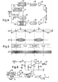
- Variable delay device 22 is driven by a clock 24 which generates a periodic series of pulses at a given frequency, and the given clock frequency is varied by a sinusoidal modulation wave, shown in Figure 2A, from a modulation signal generator 26, which may be an oscillator the frequency of which is selectable to be either approximately 1. OHz or approximately 7. OHz for "slow” and “fast” operation, respectively.
- a modulation signal generator 26 which may be an oscillator the frequency of which is selectable to be either approximately 1. OHz or approximately 7. OHz for "slow” and “fast” operation, respectively.
- the illustrated form of variable delay device is described in U.S. Patent
- variable delay device 22 The output of variable delay device 22 is applied to a filter 28 which removes from the modulated audio signal the clock pulses which have been impressed on the signal by the variable delay device.
- the variable delay device causes the time phase of the input tone signal to advance or recede in accordance with the increase or decrease of the varying voltage of the modulating wave, and consequently there is a frequency variation in accordance with the variation of the voltage of the modulating wave per unit time.
- the variable delay device causes the time phase of the tone signal to recede and causes the modulated signal to be flat with respect to the input signal, and during periods when the modulating wave is ascending in value, the phase of the musical tone signal is advanced, causing the frequency modulated signal to be sharp with respect to the input audio frequency.
- the periods during which the frequency modulated signal is sharp and flat are indicated in the diagram immediately below wavefom (B), it being understood that the degree of sharpness or flatness is not constant throughout the respective periods but varies in accordance with the voltage of the modulation wave per unit of time, with maximum sharpness and flatness occurring at zero-crossings of the modulation wave.
- the resulting frequency-modulated tone signal is applied through a switch 30 (the purpose of which will be explained presently) to a suitable power amplifier 32 for amplification prior to acoustic reproduction in a first loudspeaker 34.
- the frequency-modulated signal (B) at the output of filter 28 is also applied to the input of an amplitude modulator 40 wherein it is amplitude-modulated by the sinusoidal modulating signal (A) of the same frequency and phase as that employed to control variable delay device 22.
- Amplitude modulator 40 which may be of conventional design, is operative to provide approximately 80% modulation of the frequency-modulated input signal to produce a composite signal, substantially as illustrated in waveform (C) of Figure 2, the amplitude of which is maximum at transitions from sharp to flat of the frequency-modulated signal and minimum at transitions from flat to sharp.
- the amplitude modulator inverts the phase of the applied input signals so that the phase of the frequency-and amplitude-modulated signal at the output of the modulator is shifted by 180° relative to the input signal.
- Higher frequency components of the composite signal are removed by a filter 42, the output of which is coupled via a resistor 44 to the input terminal of a summing amplifier 46.
- the signal appearing at the output of amplifier 46 is further amplified in a suitable power amplifier 48 and applied to a second loudspeaker 50 for acoustical reproduction.
- the frequency-modulated signal appearing at the output of filter 28, in addition to being applied to amplitude modulator 40, is applied over line 52 through a capacitor 54 and a resistor 56 to the input of summing amplifier 46.
- the junction of capacitor 54 and resistor 56 is connected through a resistor 58 to ground potential.
- the frequency-modulated signal applied over this path to summing amplifier 46 is of constant amplitude, and because of the phase inversion in amplitude modulator 40, is in phase opposition with the amplitude-modulated FM signal applied to the summing amplifier via resistor 44.
- capacitor 54 and resistor 58 are selected to transmit only the higher frequencies of the audio spectrum; as a consequence, such high frequency signals applied to summing amplifier 46 via-resistor 56, as determined by the values of capacitor 54 and resistor 58, are amplitude modulated in summing amplifier 46 by the amplitude modulated FM signal from modulator 40. Only the high frequencies are affected and the modulation occurs 180° out of phase relative to the amplitude modulation of the main signal from:amplitude modulator 40.
- the resulting composite envelope for the high audio frequencies is essentially as illustrated in waveform (D) of Figure 2, in which the amplitude modulation is approximately 100% and in opposite phase relative to the amplitude modulation of lower frequencies in the system, depicted by waveform (C).
- the percentage of modulation varies with frequency, being lower at the lower end of the high frequency portion of the spectrum and increasing with frequency until a frequency is reached at which 100% modulation is approached or met; that is, where the amplitude of the high frequency signal summed into amplifier 46 via resistor 56 is substantially equal to the amplitude of the signal summed in through resistor 44 from amplitude modulator 40.
- the just-described channel simulates by electrical mixing the effects of a rotating high frequency horn and the other desirable tremulant effects
- the production of effects produced by a rotary loudspeaker depends on the acoustic mixing of the modulated tone signals produced by both speakers.
- the acoustically mixed musical tone signals will have complicated modulation effects, and they will at the same time have a rotation sound effect due to the described phase relationships between the frequency-modulated signal reproduced by speaker 34 and the composite amplitude-modulated FM signal reproduced by speaker 50.
- the placement of speakers 34 and 50 with respect to each other is not critical to obtain an acceptable spatial effect, they should be reasonably close to each other.
- speaker 50 is of the sealed enclosure type having good response at low frequencies, into which are mixed, along with the composite amplitude-modulated signal from summing amplifier 46, pedal signals, rhythm signals,accompaniment rhythms and signals representing other organ sounds. Signals representing brighter voices, such as strings, are mixed with the frequency-modulated signal from filter 28 for reproduction by speaker 34, which desirably has a better high frequency response than speaker 50.
- tibia-representing signals are applied to input terminal 20 and processed to produce the rotary loudspeaker radiation effects.
- An advantageous feature of this embodiment is that the power amplifier 32 and speaker 34 can readily be eliminated from the system by opening switch 30, and the remainder of the system used to provide a tremolo'by reproducing only the composite signal consisting of the amplitude-modulated FM signal, modulated in synchronism with each other.
- elimination of the frequency modulation channel detracts from the simulation of rotation effects, the balance of the system nevertheless produces a very pleasant tremolo effect which is quite acceptable in-an inexpensive organ utilizing a single speaker.
- the previously described characteristic of the modulation at the upper end of the audio frequency spectrum due to the summing of the high frequencies out of phase with the amplitude-and frequency-modulated main signal still obtains whether or hot speaker 34 is used.
- the system to the left of switch 30 in Figure 1 can be utilized as a building block for producing tremulant effects in an inexpensive organ otherwise requiring only one speaker, and which by adding only another speaker will provide a rotational radiation effect.
- the second embodiment of the invention is shown in Figures 4 to 6.
- the circuit of Figure 4 differs from figure 1 in that the amplitude modulator input is taken from the audio input terminal 20.
- Amplifier 48 and loudspeaker 50 then reproduce a signal which is modulated only in amplitude and not in frequency.
- the high pass filter 54, 58 and the summing amplifier 46 of Figure 1 are not shown here, but they could be included in the circuit of Figure 4.
- the musical tone signal is modulated in the other channel by a variable delay device controlled by the modulation wave from modulation signal generator 26, which, depending upon the nature of the variable delay device, is either in phase or in phase opposition with the modulating wave applied to the amplitude modulator.
- the amplitude of the modulating wave supplied to delay device 22 preferably is larger for "fast” operation than for "slow”.
- the signal produced by the frequency-modulating delay device 22 has a waveform F in Figure 5 similar to waveform B in Figure 2, and is reproduced by amplifier 32 and loudspeaker 34.
- a larger amplitude modulation wave is applied to the variable delay device when simulation of "fast” operation is desired than for "slow” operation.
- the amplitude of the modulation wave applied to the amplitude modulator is also large for "fast” operation, but is not necessarily the same amplitude as the modulating signal applied to the variable delay device.
- An amplitude modulator for achieving the output signal depicted in waveform (E) is obtainable with the modulator illustrated in Figure 6, in which the sine wave signal output of oscillator 26 is amplified in an amplifier 62 operated from a split supply so as to reference its output to +v and -v, each typically having a value of 12 volts.
- the sine wave signal from amplifier 62 is applied through a resistor 64 as a voltage control signal to a current controlled amplifier which may, for example, be an LM3080 operational transconductance amplifier, commercially available in integrated circuit from National Semiconductor and others.
- the LM 3080 is a programmable transconductance block having differential inputs and high impedance push-pull outputs.
- the device has high input impedance and its transconductance is directly proportional to the amplifier bias current.
- the device is operated from the positive side (+v) of the split supply, with half of the voltage of the positive supply applied through a resistor 68 to the minus (-) input and through a resistor 69 to the plus (+) input, to which the musical tone signal is also applied through a resistor 60.
- the output terminal of the device represented by terminal 63,is connected via a resistor 65 to half supply voltage to provide operating load for the amplifier.
- the value of resistor 64 is increased thereby to reduce the gain of amplifier 66 to provide a modulated signal of lower amplitude for "slow” operation than for "fast”. This may be accomplished by a switch 67 connected to partially shunt resistor 64 when "fast" operation is desired.
- variable delay device (frequency modulator) 22 and in the amplitude modulator 40 can be increased for fast sub-audio modulating frequencies, e.g. 7Hz, and decreased for slow frequencies, e.g. lHz.
- rotatable tremulant sound producers described in the aforementioned Re.23,323 are two which each use a single speaker to produce the tremulant effect.
- a stationary speaker delivers sound to a rotating directional horn which, because of the bend of the horn, causes some attenuation of high frequencies contained in the sound delivered by the speaker to the horn.
- a speaker is enclosed in a casing filed with sound absorbent material to prevent sound radiation from the back of the speaker, a directional horn is mounted on the front of the casing for cooperation with the speaker, and the whole assembly is supported to be driven in rotation about a vertical axis.
- the shape of the horn is such that there is little or no attenuation of high frequencies.
- the present invention affords the option of simulating either one or the other of these electro-mechanical systems.
- filters 42 and 28 are provided in their respective channels to attenuate high frequencies contained in the amplitude-and frequency- modulated signals, respectively having a gradual rolloff at about 2000 Hz.
- filters 42 and 28 are omitted.
Landscapes
- Physics & Mathematics (AREA)
- Engineering & Computer Science (AREA)
- Acoustics & Sound (AREA)
- Multimedia (AREA)
- Stereophonic System (AREA)
- Circuit For Audible Band Transducer (AREA)
Applications Claiming Priority (4)
| Application Number | Priority Date | Filing Date | Title |
|---|---|---|---|
| US06/107,220 US4308422A (en) | 1979-12-26 | 1979-12-26 | Circuit for modulating a musical tone signal to produce a rotating effect |
| US06/107,203 US4308428A (en) | 1979-12-26 | 1979-12-26 | System for electronically simulating radiation effects produced by a rotary loudspeaker |
| US107220 | 1979-12-26 | ||
| US107203 | 1998-06-29 |
Publications (2)
| Publication Number | Publication Date |
|---|---|
| EP0031692A2 true EP0031692A2 (de) | 1981-07-08 |
| EP0031692A3 EP0031692A3 (de) | 1981-07-29 |
Family
ID=26804508
Family Applications (1)
| Application Number | Title | Priority Date | Filing Date |
|---|---|---|---|
| EP80304625A Ceased EP0031692A3 (de) | 1979-12-26 | 1980-12-19 | Elektronische Schaltung zum Nachbilden des Klangs eines rotierenden Lautsprechers |
Country Status (1)
| Country | Link |
|---|---|
| EP (1) | EP0031692A3 (de) |
Cited By (1)
| Publication number | Priority date | Publication date | Assignee | Title |
|---|---|---|---|---|
| CN113012663A (zh) * | 2019-12-20 | 2021-06-22 | 雅马哈株式会社 | 声音信号变换装置、乐器、声音信号变换方法及声音信号变换程序 |
Family Cites Families (1)
| Publication number | Priority date | Publication date | Assignee | Title |
|---|---|---|---|---|
| US3979991A (en) * | 1968-05-22 | 1976-09-14 | Matsushita Electric Industrial Co., Ltd. | Electronic expression device for producing tremulant effect |
-
1980
- 1980-12-19 EP EP80304625A patent/EP0031692A3/de not_active Ceased
Cited By (2)
| Publication number | Priority date | Publication date | Assignee | Title |
|---|---|---|---|---|
| CN113012663A (zh) * | 2019-12-20 | 2021-06-22 | 雅马哈株式会社 | 声音信号变换装置、乐器、声音信号变换方法及声音信号变换程序 |
| CN113012663B (zh) * | 2019-12-20 | 2023-11-07 | 雅马哈株式会社 | 声音信号变换装置、乐器、声音信号变换方法及声音信号变换程序 |
Also Published As
| Publication number | Publication date |
|---|---|
| EP0031692A3 (de) | 1981-07-29 |
Similar Documents
| Publication | Publication Date | Title |
|---|---|---|
| US3665105A (en) | Method and apparatus for simulating location and movement of sound | |
| US4000676A (en) | Electronic vibrato system | |
| JPH0546168A (ja) | Midiシンセサイザにおけるデジタル・フイルタとデジタル・ミユージツク・シンセサイザの出力にフイルタをかける方法 | |
| WO2015038136A1 (en) | Apparatus and method for a celeste in an electronically-orbited speaker | |
| US4308428A (en) | System for electronically simulating radiation effects produced by a rotary loudspeaker | |
| US4008641A (en) | Device for modulating a musical tone signal to produce a rotating sound effect | |
| US3719782A (en) | System for changing the output response characteristics of an acoustic input | |
| GB2202111A (en) | Reverb generator | |
| US4308422A (en) | Circuit for modulating a musical tone signal to produce a rotating effect | |
| CA1095836A (en) | Device for electronically generating the radiation effects produced by a rotary loudspeaker | |
| US10249276B2 (en) | Rotating speaker array | |
| US4329902A (en) | Electronic method and apparatus for modifying musical sound | |
| US5442711A (en) | Acoustic signal processing unit | |
| US5848166A (en) | Hybrid electronic and electromechanical device for the production of tremulant sound | |
| EP0031692A2 (de) | Elektronische Schaltung zum Nachbilden des Klangs eines rotierenden Lautsprechers | |
| US3040613A (en) | Electrical musical system | |
| US3973462A (en) | Frequency-deviation method and apparatus | |
| US4064778A (en) | Frequency-deviation method and apparatus | |
| US3943465A (en) | Frequency-deviation method and apparatus | |
| JPS6253100A (ja) | 音響特性制御装置 | |
| US3973223A (en) | Frequency-deviation method and apparatus | |
| US3586783A (en) | Sound system with enhanced low frequency distribution | |
| US1853286A (en) | Transmission and reproduction of sound | |
| US4035582A (en) | Tremolo effect producing system | |
| US4280388A (en) | Apparatus and method for generating chorus and celeste tones |
Legal Events
| Date | Code | Title | Description |
|---|---|---|---|
| PUAI | Public reference made under article 153(3) epc to a published international application that has entered the european phase |
Free format text: ORIGINAL CODE: 0009012 |
|
| PUAL | Search report despatched |
Free format text: ORIGINAL CODE: 0009013 |
|
| AK | Designated contracting states |
Designated state(s): GB IT NL |
|
| AK | Designated contracting states |
Designated state(s): GB IT NL |
|
| 17P | Request for examination filed |
Effective date: 19811002 |
|
| STAA | Information on the status of an ep patent application or granted ep patent |
Free format text: STATUS: THE APPLICATION HAS BEEN REFUSED |
|
| 18R | Application refused |
Effective date: 19830713 |
|
| RIN1 | Information on inventor provided before grant (corrected) |
Inventor name: FINCH, ROBERT A. Inventor name: SCHMOLL, GEORGE F. III |