EP0031739A1 - Presswerkzeug zum Formen von Statorwicklungen an beiden Seiten eines Stators und mittels dieses Presswerkzeuges erhaltene Statorwicklungen - Google Patents
Presswerkzeug zum Formen von Statorwicklungen an beiden Seiten eines Stators und mittels dieses Presswerkzeuges erhaltene Statorwicklungen Download PDFInfo
- Publication number
- EP0031739A1 EP0031739A1 EP80401682A EP80401682A EP0031739A1 EP 0031739 A1 EP0031739 A1 EP 0031739A1 EP 80401682 A EP80401682 A EP 80401682A EP 80401682 A EP80401682 A EP 80401682A EP 0031739 A1 EP0031739 A1 EP 0031739A1
- Authority
- EP
- European Patent Office
- Prior art keywords
- forming
- press
- plate
- press tool
- matrix
- Prior art date
- Legal status (The legal status is an assumption and is not a legal conclusion. Google has not performed a legal analysis and makes no representation as to the accuracy of the status listed.)
- Granted
Links
- 238000004804 winding Methods 0.000 title 2
- 239000011159 matrix material Substances 0.000 claims description 27
- 238000005096 rolling process Methods 0.000 claims description 2
- 230000007246 mechanism Effects 0.000 description 3
- XEEYBQQBJWHFJM-UHFFFAOYSA-N Iron Chemical compound [Fe] XEEYBQQBJWHFJM-UHFFFAOYSA-N 0.000 description 2
- 230000000712 assembly Effects 0.000 description 2
- 238000000429 assembly Methods 0.000 description 2
- 238000000354 decomposition reaction Methods 0.000 description 2
- 238000006073 displacement reaction Methods 0.000 description 1
- 229910052742 iron Inorganic materials 0.000 description 1
- 238000004519 manufacturing process Methods 0.000 description 1
- 230000002093 peripheral effect Effects 0.000 description 1
- 230000000717 retained effect Effects 0.000 description 1
Images

Classifications
-
- H—ELECTRICITY
- H02—GENERATION; CONVERSION OR DISTRIBUTION OF ELECTRIC POWER
- H02K—DYNAMO-ELECTRIC MACHINES
- H02K15/00—Processes or apparatus specially adapted for manufacturing, assembling, maintaining or repairing of dynamo-electric machines
- H02K15/20—Shaping or compacting conductors or winding heads after the installation of the winding in the cores or machines; Applying fastening means on winding heads
- H02K15/24—Shaping or compacting winding heads
Definitions
- the present invention relates to the production of a press tool intended for forming the coil heads which are located on either side of a motor stator.
- this operation is carried out from a forming machine in which the different movements have their own origins and are independent from each other.
- the invention provides a press tool for forming the coil heads on either side of an electric motor stator, in internal and external dimensions and in height, mounted in two forming parts on a press table and nose, the two forming parts being of identical structures and each comprising a set of lateral cams and a central cam of such a profile that during the same press down movement, the simultaneous forming of the two lower and upper coil heads is provided in two phases.
- Figure 1 is a sectional view of the tool, the stator being in place, the press starting its descent.
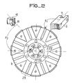
- FIG. 2 is a top view of the plate 3.
- the tool which will be described with the aid of FIG. 1 makes it possible, firstly, to obtain the external and internal movements simultaneously or not in order to form the bun at diameters B and C and, then to put the bun at the height H.
- This decomposition of the forming into at least two phases is essential to obtain a good quality of forming.
- the tool is built in two parts: the lower part is fixed on the press table; the upper part is coupled to the press nose.
- the lower part consists of a sole 2 which fixes it to the press table, not shown.
- On this sole 2 rest the central pyramidal cam 4 and several peripheral cams 5 as well as chan delles 14 which support a crown which one calls "Bottom of matrix” 13,
- the cam 4 and the candles 14 are fixed on the sole 2 by means of a wedging washer 15 aimed on this same sole 2.
- On the cam 4 which has a cylindrical body slides a plate 3. At rest it is retained on the bottom of the matrix 13 and maintained in this position under the action of springs 18 guided by rods 19.
- the plate 3 has several radial grooves.
- these radial grooves are each represented in two parts bounded by the circular groove 22 which receives the bottom of the die 13.
- This groove divides the plate 3 into two zones.
- the outer zone has grooves 23, each receiving an outer matrix element 6.
- the arrow F 1 indicates the positioning of the axis of symmetry of the matrix element 6.
- the inner zone has grooves 25 with a flat bottom, the arrow F 2 placing the axis of symmetry of one of the elements of inner matrix 10 which is inserted therein.
- a cover 17 and a crown cap 16 are fixed by screws to the plate 3 and thus complete the guiding of the matrix elements 6 and 10.
- the external matrix element 6 of parallelepipedal force has towards the center, the forming part in an arc in circle and at the rear, a yoke which receives a roller 7.
- a stop 9 integral with the matrix element 6 receives a permanent thrust under the action of the spring 8 which exerts a sufficient force to keep the contact between the roller 7 and cam 5.
- the inner matrix element 10 the forming part of which is in an arc, has a yoke at the rear which receives a roller 11.
- the permanent contact between the roller 11 and one of the facets of the cam 4 is ensured by a spring rubber crown 12.
- This spring is placed in a groove made in the interior matrix elements 10.
- the upper part is identical to the lower part, the sole 1 differing from the sole 2 only by the presence of the fastening elements on the press nose.
- the upper and lower parts may be different in size.
- the buns may also not have a circular shape and a constant height H. In this case, it suffices to adapt the profile of the matrix elements and of the matrix base to the buns.
- the operation of the tool is based on the decomposition of a vertical movement given by the press cylinder, into several radial movements received by the die elements.
- the motors of these resulting movements are rollers rolling on cams.
- the stator 20 is the connecting element between the lower and upper parts. It receives the movement from the upper part and transmits it to the lower part. By means of a prior balance between the two parties, we verify that they act simultaneously. The upper and lower parts travel their way at the same time.
- the forming operation takes place as follows. At rest, the upper part of the tool is raised enough to allow the stator to access the lower part. The stator rests on the cover 17 of the lower part. The upper part descends and comes to bear on the face A of the stator, by means of the cover 17a of the upper part. It is the first phase of forming. The rollers 7 and 11 roll on the slopes of the cams 5 and 4 and cause the displacement of the matrix elements 6 and 10 towards the bun 21.
- the end of the first phase corresponds to the instant when the rollers 7 and 11 pass from the sloping face of the cams 5 and 4 to the vertical face.
- the diameters B and C of the bun are formed and the faces in an arc of the matrix elements 6 and 10 are contiguous with those of the matrix bottom 13. The bun is trapped.
- the matrix elements 6 and 10 no longer move because their rollers roll on a vertical face and parallel to the direction of movement given by the press cylinder.
- the plate 3 comes to bear on the setting washer 15.
- the height H of the bun is obtained.
- the upper part rises, the mechanism resumes its rest position.
- the stator buns are formed.
- Recesses can be arranged by matrix elements of predetermined shape.
Landscapes
- Engineering & Computer Science (AREA)
- Manufacturing & Machinery (AREA)
- Power Engineering (AREA)
- Press Drives And Press Lines (AREA)
Applications Claiming Priority (2)
| Application Number | Priority Date | Filing Date | Title |
|---|---|---|---|
| FR7931490A FR2472295A1 (fr) | 1979-12-21 | 1979-12-21 | Outil de presse destine au formage des tetes de bobines disposees de part et d'autre d'un stator, et tetes de bobines obtenues a l'aide d'un tel outil |
| FR7931490 | 1979-12-21 |
Publications (2)
| Publication Number | Publication Date |
|---|---|
| EP0031739A1 true EP0031739A1 (de) | 1981-07-08 |
| EP0031739B1 EP0031739B1 (de) | 1983-10-19 |
Family
ID=9233099
Family Applications (1)
| Application Number | Title | Priority Date | Filing Date |
|---|---|---|---|
| EP80401682A Expired EP0031739B1 (de) | 1979-12-21 | 1980-11-25 | Presswerkzeug zum Formen von Statorwicklungen an beiden Seiten eines Stators und mittels dieses Presswerkzeuges erhaltene Statorwicklungen |
Country Status (3)
| Country | Link |
|---|---|
| EP (1) | EP0031739B1 (de) |
| DE (1) | DE3065396D1 (de) |
| FR (1) | FR2472295A1 (de) |
Cited By (6)
| Publication number | Priority date | Publication date | Assignee | Title |
|---|---|---|---|---|
| WO1992005619A1 (en) * | 1990-09-20 | 1992-04-02 | Advanced Machine And Tool Corporation | Apparatus for forming of stator coil end turns |
| WO1997034358A1 (en) * | 1996-03-12 | 1997-09-18 | Statomat Special Machines Limited | Press tools |
| WO1998038722A1 (de) * | 1997-02-28 | 1998-09-03 | Elmotec Elektro-Motoren-Technik Gmbh | Vorrichtung zum einziehen von spulen in nuten von statorblechpaketen elektrischer maschinen |
| EP1304789A1 (de) * | 2001-10-12 | 2003-04-23 | Pavesi S.R.L. | Verfahren und Vorrichtung zur Formung von Wickelköpfen am Kern einer elektrodynamichen Maschine |
| CN103227538A (zh) * | 2013-04-23 | 2013-07-31 | 大连德新机电技术工程有限公司 | 绕线铁芯前后端整形捆扎工件翻转装置 |
| FR3164854A1 (fr) * | 2024-07-16 | 2026-01-23 | Ampere Sas | Outil de formage de chignon de stator et procédé mettant en œuvre un tel outil |
Families Citing this family (1)
| Publication number | Priority date | Publication date | Assignee | Title |
|---|---|---|---|---|
| CN105344827A (zh) * | 2015-11-30 | 2016-02-24 | 宁波东港紧固件制造有限公司 | 一种微电机壳一次成型模具 |
Citations (3)
| Publication number | Priority date | Publication date | Assignee | Title |
|---|---|---|---|---|
| US3593405A (en) * | 1969-09-05 | 1971-07-20 | Gen Electric | Apparatus for forming winding end turns |
| FR2146431A1 (de) * | 1971-07-20 | 1973-03-02 | Appt E | |
| FR2258035A1 (de) * | 1974-01-14 | 1975-08-08 | Gen Electric |
-
1979
- 1979-12-21 FR FR7931490A patent/FR2472295A1/fr active Granted
-
1980
- 1980-11-25 DE DE8080401682T patent/DE3065396D1/de not_active Expired
- 1980-11-25 EP EP80401682A patent/EP0031739B1/de not_active Expired
Patent Citations (3)
| Publication number | Priority date | Publication date | Assignee | Title |
|---|---|---|---|---|
| US3593405A (en) * | 1969-09-05 | 1971-07-20 | Gen Electric | Apparatus for forming winding end turns |
| FR2146431A1 (de) * | 1971-07-20 | 1973-03-02 | Appt E | |
| FR2258035A1 (de) * | 1974-01-14 | 1975-08-08 | Gen Electric |
Cited By (9)
| Publication number | Priority date | Publication date | Assignee | Title |
|---|---|---|---|---|
| WO1992005619A1 (en) * | 1990-09-20 | 1992-04-02 | Advanced Machine And Tool Corporation | Apparatus for forming of stator coil end turns |
| WO1997034358A1 (en) * | 1996-03-12 | 1997-09-18 | Statomat Special Machines Limited | Press tools |
| US6155094A (en) * | 1996-03-12 | 2000-12-05 | Statomat Special Machines Ltd. | Pressing tool for forming winding end turns in a stator |
| WO1998038722A1 (de) * | 1997-02-28 | 1998-09-03 | Elmotec Elektro-Motoren-Technik Gmbh | Vorrichtung zum einziehen von spulen in nuten von statorblechpaketen elektrischer maschinen |
| EP1304789A1 (de) * | 2001-10-12 | 2003-04-23 | Pavesi S.R.L. | Verfahren und Vorrichtung zur Formung von Wickelköpfen am Kern einer elektrodynamichen Maschine |
| CN103227538A (zh) * | 2013-04-23 | 2013-07-31 | 大连德新机电技术工程有限公司 | 绕线铁芯前后端整形捆扎工件翻转装置 |
| CN103227538B (zh) * | 2013-04-23 | 2015-05-20 | 大连德新机电技术工程有限公司 | 绕线铁芯前后端整形捆扎工件翻转装置 |
| FR3164854A1 (fr) * | 2024-07-16 | 2026-01-23 | Ampere Sas | Outil de formage de chignon de stator et procédé mettant en œuvre un tel outil |
| EP4693849A1 (de) * | 2024-07-16 | 2026-02-11 | Ampere SAS | Werkzeug zum formen von stator-chitosen und verfahren zur verwendung eines solchen werkzeugs |
Also Published As
| Publication number | Publication date |
|---|---|
| DE3065396D1 (en) | 1983-11-24 |
| FR2472295A1 (fr) | 1981-06-26 |
| EP0031739B1 (de) | 1983-10-19 |
| FR2472295B1 (de) | 1983-01-21 |
Similar Documents
| Publication | Publication Date | Title |
|---|---|---|
| FR2478497A1 (fr) | Presse a poinconner a tourelles porte-outils | |
| FR2535244A1 (fr) | Presse a poinconner | |
| FR2596319A1 (fr) | Appareil de bombage pour plieuse | |
| EP0031739A1 (de) | Presswerkzeug zum Formen von Statorwicklungen an beiden Seiten eines Stators und mittels dieses Presswerkzeuges erhaltene Statorwicklungen | |
| FR2922127A1 (fr) | Machine a cintrer un profile et outillage de cintrage pour une telle machine | |
| EP0491602B1 (de) | Vorrichtung zum Formstanzen von Blattmaterialen, insbesondere von Blechplättchen | |
| CN114083285B (zh) | 一种装弹簧机构及应用于带弹簧产品的组装设备 | |
| JP2002321014A (ja) | 寄曲加工用カム装置 | |
| FR2481584A1 (fr) | Appareil pour former un intervalle depourvu d'elements d'accouplement sur deux bandes continues de fermeture a glissiere | |
| FR2625454A1 (fr) | Outil a suivre pour presse d'emboutissage | |
| US1830021A (en) | Clothespin assembling machine | |
| CN218449825U (zh) | 一种端盖轴承组装用定位台 | |
| KR20130001637A (ko) | 사이징 가공장치 | |
| CN110492694A (zh) | 一种单根转轴连续自动上料的电机组装机 | |
| JPH0327698Y2 (de) | ||
| WO2001026867A1 (fr) | Machine automatique d'assemblage de cadres | |
| EP3538292B1 (de) | Presswerkzeug für metallblech mit relativ grossen abmessungen, insbesondere für kraftfahrzeuge | |
| EP0997208A1 (de) | Werkstücktransfervorrichtung zwischen zwei Arbeitsstationen eines Pressenwerkzeuges | |
| US5996198A (en) | Apparatus for ribbing cloth venetian blind strips | |
| JPH043694Y2 (de) | ||
| FR2644102A1 (fr) | Dispositif permettant de realiser une presse hydraulique a au moins un axe de poussee deplacable sur toute la zone de travail, a la demande | |
| CN112133551B (zh) | 铁芯装配平台 | |
| JPS6019314Y2 (ja) | クロスバ−組立装置 | |
| FR2628015A1 (fr) | Poinconneuse avec dispositif de commande pour la levee du chariot porte-outil | |
| FR2678900A1 (fr) | Machine pour la fermeture d'un conteneur, tel qu'une barquette en un materiau semi-rigide au moyen d'un couvercle. |
Legal Events
| Date | Code | Title | Description |
|---|---|---|---|
| PUAI | Public reference made under article 153(3) epc to a published international application that has entered the european phase |
Free format text: ORIGINAL CODE: 0009012 |
|
| AK | Designated contracting states |
Designated state(s): DE GB IT |
|
| 17P | Request for examination filed |
Effective date: 19810805 |
|
| ITF | It: translation for a ep patent filed | ||
| GRAA | (expected) grant |
Free format text: ORIGINAL CODE: 0009210 |
|
| AK | Designated contracting states |
Designated state(s): DE GB IT |
|
| REF | Corresponds to: |
Ref document number: 3065396 Country of ref document: DE Date of ref document: 19831124 |
|
| PLBE | No opposition filed within time limit |
Free format text: ORIGINAL CODE: 0009261 |
|
| STAA | Information on the status of an ep patent application or granted ep patent |
Free format text: STATUS: NO OPPOSITION FILED WITHIN TIME LIMIT |
|
| 26N | No opposition filed | ||
| ITTA | It: last paid annual fee | ||
| PGFP | Annual fee paid to national office [announced via postgrant information from national office to epo] |
Ref country code: GB Payment date: 19951020 Year of fee payment: 16 |
|
| PGFP | Annual fee paid to national office [announced via postgrant information from national office to epo] |
Ref country code: DE Payment date: 19951021 Year of fee payment: 16 |
|
| PG25 | Lapsed in a contracting state [announced via postgrant information from national office to epo] |
Ref country code: GB Effective date: 19961125 |
|
| GBPC | Gb: european patent ceased through non-payment of renewal fee |
Effective date: 19961125 |
|
| PG25 | Lapsed in a contracting state [announced via postgrant information from national office to epo] |
Ref country code: DE Effective date: 19970801 |