EP0031755A2 - Elektrischer Haushalts-Kochofen - Google Patents
Elektrischer Haushalts-Kochofen Download PDFInfo
- Publication number
- EP0031755A2 EP0031755A2 EP80401799A EP80401799A EP0031755A2 EP 0031755 A2 EP0031755 A2 EP 0031755A2 EP 80401799 A EP80401799 A EP 80401799A EP 80401799 A EP80401799 A EP 80401799A EP 0031755 A2 EP0031755 A2 EP 0031755A2
- Authority
- EP
- European Patent Office
- Prior art keywords
- turbine
- thermostat
- pyrolysis
- infinite
- oven
- Prior art date
- Legal status (The legal status is an assumption and is not a legal conclusion. Google has not performed a legal analysis and makes no representation as to the accuracy of the status listed.)
- Withdrawn
Links
Images




Classifications
-
- F—MECHANICAL ENGINEERING; LIGHTING; HEATING; WEAPONS; BLASTING
- F24—HEATING; RANGES; VENTILATING
- F24C—DOMESTIC STOVES OR RANGES ; DETAILS OF DOMESTIC STOVES OR RANGES, OF GENERAL APPLICATION
- F24C14/00—Stoves or ranges having self-cleaning provisions, e.g. continuous catalytic cleaning or electrostatic cleaning
- F24C14/02—Stoves or ranges having self-cleaning provisions, e.g. continuous catalytic cleaning or electrostatic cleaning pyrolytic type
-
- F—MECHANICAL ENGINEERING; LIGHTING; HEATING; WEAPONS; BLASTING
- F24—HEATING; RANGES; VENTILATING
- F24C—DOMESTIC STOVES OR RANGES ; DETAILS OF DOMESTIC STOVES OR RANGES, OF GENERAL APPLICATION
- F24C15/00—Details
- F24C15/32—Arrangements of ducts for hot gases, e.g. in or around baking ovens
- F24C15/322—Arrangements of ducts for hot gases, e.g. in or around baking ovens with forced circulation
- F24C15/325—Arrangements of ducts for hot gases, e.g. in or around baking ovens with forced circulation electrically-heated
Definitions
- the present invention relates to improvements in the electric cooking oven for household use described in French patent No. 75 37 589 (publication No. 2 334 916).
- the invention relates more precisely to the embodiment of this oven in which a system for cleaning the walls by pyrolysis is provided.
- the turbine compartment is equipped with a manually operable shutter, making it possible to close the air suction openings, to suppress the convection of forced air inside the oven during cleaning, while keeping the turbine running.
- the electric cooking oven targeted by the present invention comprises a cooking enclosure inside which is established a forced convection of air heated by at least one electrical resistance and pulsed by the above-mentioned centrifugal turbine, mounted in a compartment attached to one of the walls of the enclosure, this tubing being surrounded by an openwork sleeve preferably made of stainless steel, placed in contact with the heating resistor so that it can be brought to red by the latter.
- the electrical circuit for controlling the pyrolysis cleaning operation is equipped with an energy metering device constituted by an infinite connected, on the one hand to a first control thermostat and on the other hand to the resistors ensuring pyrolysis, and the turbine is connected to a safety device in such a way that, being first of all at a standstill at the start of the pyrolysis operation, said turbine starts to operate automatically from a predetermined critical temperature, which allows ventilation of the turbine from this critical temperature during pyrolysis.
- the electrical supply of the resistance of the furnace is modulated by the beats of the infinite movable contact, so that in practice the maximum pyrolysis temperature remains around 460 to 500 °. C, the infinite ensuring a succession of heating and stopping sequences by its beats.
- the electrical circuit provided by the invention automatically starts the turbine, which is thus ventilated as long as the temperature remains above this critical temperature, which is of the order of 460 ° C.
- the turbine is connected to a second thermostat adjusted so as to close at the critical temperature from which the turbine must be ventilated for its protection, and to a flap or valve of the device. safety, the connections being made so that the closing of the second thermostat starts the turbine which then actuates the safety shutter, then the ventilation of said second thermostat by the turbine causes the opening of this thermostat, the electrical supply of the turbine remaining ensured via the safety shutter during pyrolysis, while the supply of the pyrolysis resistance is modulated by the beats of infinite.
- the turbine being advantageously provided with a second rotor, it is understood that this rotor effectively protects the turbine proper by its ventilation during the entire pyrolysis operation, the pyrolysis temperature not exceeding substantially 460 to 500 ° C.
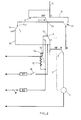
- FIG. 1 shows the electrical circuit for controlling the cleaning operation by pyrolysis of the electric cooking oven for household use covered by the invention.
- This furnace also being in accordance with French patent - No. 2 334 916 and in particular with the embodiment comprising a turbine with two rotors, the second rotor ensuring the cooling of the drive motor of the turbine and of at least part of the external walls of the furnace during pyrolysis, these parts have not been shown. They will therefore not be described here.
- the circuit illustrated diagrammatically in FIG. 1 is equipped, in accordance with the present invention, with an energy metering device constituted by an infinite 1, connected on the one hand to a first control thermostat 2 and on the other hand to the resistance RG grill which is supplied during pyrolysis.
- a pyrolysis programmer 9 is placed in series with the resistance RG.
- Infinite 1 is produced in a manner known per se, essentially by a bimetallic strip comprising a fixed contact 3a placed opposite a movable contact 3b, this bimetallic strip being heated by a resistor 10; the movable contact 3b deviates and applies periodically against the fixed contact 3a when the resistor 10 is supplied, the infinite thus operates according to alternative supply and stop sequences.
- the duration of these successive stop-supply cycles is determined by known adjustment means and not shown.
- the oven also has a turbine 4, the normal function of which is to ventilate the interior of the oven, and which must be protected against excessive heating during pyrolysis.
- the turbine 4 is connected, according to a complementary characteristic of the invention, to a safety device essentially consisting of a pivoting flap 5 placed opposite the turbine 4, the connection between the latter and the flap 5 or micro-valve. being symbolized by the broken line 6.
- the pivoting flap 5 can take two positions: a first position referenced 1, in which it provides the connection between the thermostat 2 which feeds the infinite 1, in this case a baking thermostat of 300 ° C, and a second position referenced 2, in which it establishes the connection between the thermostat 2 and a three-stage thermostat 7, for example with the 90 ° C stage of the latter.
- a switch 8 is interposed between the thermostat 7 and the turbine 4, this switch establishing the connection between the aforementioned elements when it is on the pad referenced 3, and establishing the connection between the turbine 4 and a pastry-meat inverter 11, when '' it is placed on the pad referenced 2.
- An RF resistance heating the furnace is connected to the thermostat 7 with the interposition of a switch 16.
- the inverter 11 is connected on the one hand to the cooking thermostat 2, and on the other hand to the supply sector 12 by a connection 13.
- the turbine 4 is connected to a thermostat 14 adjusted so as to close at the critical temperature from which the turbine 4 must be ventilated for its protection, that is to say 460 ° C in the example described.
- Thermostat 14 can be three-stage, and it is also connected to cooking thermostat 2 which feeds infinite 1.
- the connection between thermostat 14 and turbine 4 is established via switch 8, thermostat 7 with three floors, and a connection 15.
- the pad 2a of the thermostat 2 is connected to the pad 14a of the thermostat 14 around which it pivots, to the pad 5a of the safety device 5 located in the cooling air stream, as well as to the contact pad of the infinity 1 and finally to the inverter 11.
- the cooking thermostat 2 is connected to the safety contact constituted by the flap 5 which is on its pad 1, the infinite 1 is supplied by its two terminals as well as by the grill resistance RG.
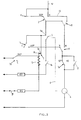
- the 90 ° C stage of the three-stage thermostat 7 closes, then the thermostat 2 set for example at 300 ° C, and finally the thermostat 14 set at the critical temperature of 460 ° C. These elements then take positions which are represented in FIG. 2.
- the turbine 4 then cools the thermostat 14 by 460 ° C., which returns correlatively to its initial position, referenced 0 and therefore becomes ineffective (FIG. 3). Furthermore, the mobile contact 3b of the infinite 1 opens and closes periodically on the fixed contact 3a, so that the resistance RG of pyrolysis has its power supply modulated accordingly, correlative to the opening and closing cycle. from contact 3b to fixed contact 3a. Under these conditions, the pyrolysis temperature practically levels from 460 to 500 ° C. approximately.
- the turbine 4 is therefore in a way self-ventilated by its second rotor, and stirs the air in the cooking chamber, which ensures better cleaning. from the oven door.
- Another advantage of the control circuit according to the invention lies in the fact that the mixing of the air provided by the turbine 4 from 460 ° C., ensures the elimination of the fumes by lack of overpressure, as well as the respect of the standards for the carbon monoxide / carbon dioxide ratio.
- the infinite 1 is controlled by the three-stage thermostat 7, and more precisely in the example shown, by the second stage 7b of the latter, set from 0 to 330 ° C. Furthermore, the connections and arrangement of the circuit are the same as those of FIGS. 1 to 3. However, the first stage 7a of the three-stage thermostat 7 is placed between the switch 8 and the turbine 4, and a second contact 17 of the switch is connected to the terminals of the first stage 7a of the thermostat 7.
- the pyrolysis resistance RG is supplied earlier than in the previous embodiment, which allows a much slower rise in oven temperature, and correspondingly an overpressure of the fumes as well as an improved carbon monoxide / carbon dioxide ratio. .
- the present invention is not limited to the embodiments described and may include variant embodiments.
Landscapes
- Engineering & Computer Science (AREA)
- Chemical & Material Sciences (AREA)
- Combustion & Propulsion (AREA)
- Mechanical Engineering (AREA)
- General Engineering & Computer Science (AREA)
- Chemical Kinetics & Catalysis (AREA)
- Electric Stoves And Ranges (AREA)
- Baking, Grill, Roasting (AREA)
Applications Claiming Priority (2)
| Application Number | Priority Date | Filing Date | Title |
|---|---|---|---|
| FR7931753 | 1979-12-27 | ||
| FR7931753A FR2472723A2 (fr) | 1975-12-09 | 1979-12-27 | Four electrique de cuisson a usage menager |
Publications (2)
| Publication Number | Publication Date |
|---|---|
| EP0031755A2 true EP0031755A2 (de) | 1981-07-08 |
| EP0031755A3 EP0031755A3 (de) | 1981-07-15 |
Family
ID=9233189
Family Applications (1)
| Application Number | Title | Priority Date | Filing Date |
|---|---|---|---|
| EP80401799A Withdrawn EP0031755A3 (de) | 1979-12-27 | 1980-12-12 | Elektrischer Haushalts-Kochofen |
Country Status (4)
| Country | Link |
|---|---|
| US (1) | US4413171A (de) |
| EP (1) | EP0031755A3 (de) |
| JP (1) | JPS56100238A (de) |
| ES (1) | ES8204134A2 (de) |
Cited By (3)
| Publication number | Priority date | Publication date | Assignee | Title |
|---|---|---|---|---|
| FR2517810A1 (fr) * | 1981-12-08 | 1983-06-10 | Scholtes Ets Eugen | Four electrique de cuisson a usage menager |
| EP0410174A3 (en) * | 1989-07-26 | 1991-06-05 | Bosch-Siemens Hausgeraete Gmbh | Oven with pyrolytically cleaned muffle |
| FR2679629A1 (fr) * | 1991-07-25 | 1993-01-29 | Soremam | Procede et dispositif simplifies de controle du nettoyage pyrolytique d'un four electrique menager. |
Families Citing this family (4)
| Publication number | Priority date | Publication date | Assignee | Title |
|---|---|---|---|---|
| US5786567A (en) * | 1997-01-30 | 1998-07-28 | Wang; Ching-Hsiang | Oven |
| US6244165B1 (en) | 1998-08-17 | 2001-06-12 | Joseph S. Trombley | Integrated cooling, heating food preparation system |
| US7174720B2 (en) * | 2003-07-07 | 2007-02-13 | Kennedy Brian C | Cooker utilizing a peltier device |
| RU180073U1 (ru) * | 2017-12-08 | 2018-06-01 | Федеральное государственное бюджетное образовательное учреждение высшего образования "Казанский национальный исследовательский технический университет им. А.Н. Туполева - КАИ" (КНИТУ-КАИ) | Газотурбинный двигатель с двумя камерами сгорания |
Family Cites Families (4)
| Publication number | Priority date | Publication date | Assignee | Title |
|---|---|---|---|---|
| US3587555A (en) * | 1969-05-13 | 1971-06-28 | Jenn Air Corp | Ventilated range |
| DE2341574A1 (de) * | 1973-08-17 | 1975-02-27 | Jega Friedrichsthaler Eisen | Elektrische schaltung fuer einen kombinierten elektroherd mit widerstandsbeheizung, mit hf-garungseinrichtung und mit einer einrichtung zur pyrolytischen selbstreinigung |
| FR2334916A1 (fr) * | 1975-12-09 | 1977-07-08 | Scholtes Ets Eugen | Four electrique de cuisson a usage menager |
| US4071738A (en) * | 1976-01-06 | 1978-01-31 | Jenn Air Corporation | Ventilated range with convertible radiant convection oven |
-
1980
- 1980-12-12 EP EP80401799A patent/EP0031755A3/de not_active Withdrawn
- 1980-12-26 ES ES498178A patent/ES8204134A2/es not_active Expired
- 1980-12-27 JP JP18948480A patent/JPS56100238A/ja active Pending
-
1981
- 1981-12-08 US US06/328,643 patent/US4413171A/en not_active Expired - Fee Related
Cited By (4)
| Publication number | Priority date | Publication date | Assignee | Title |
|---|---|---|---|---|
| FR2517810A1 (fr) * | 1981-12-08 | 1983-06-10 | Scholtes Ets Eugen | Four electrique de cuisson a usage menager |
| EP0081420A3 (de) * | 1981-12-08 | 1984-08-22 | Etablissements Eugene Scholtes | Elektrischer Haushaltskochherd |
| EP0410174A3 (en) * | 1989-07-26 | 1991-06-05 | Bosch-Siemens Hausgeraete Gmbh | Oven with pyrolytically cleaned muffle |
| FR2679629A1 (fr) * | 1991-07-25 | 1993-01-29 | Soremam | Procede et dispositif simplifies de controle du nettoyage pyrolytique d'un four electrique menager. |
Also Published As
| Publication number | Publication date |
|---|---|
| ES498178A0 (es) | 1982-04-01 |
| US4413171A (en) | 1983-11-01 |
| EP0031755A3 (de) | 1981-07-15 |
| ES8204134A2 (es) | 1982-04-01 |
| JPS56100238A (en) | 1981-08-12 |
Similar Documents
| Publication | Publication Date | Title |
|---|---|---|
| EP0447979B1 (de) | Verfahren zum Backen für einen Ofen mit Mikrowellen-, Konvektions- und Infrarotheizung | |
| FR2470575A1 (fr) | Appareil electrique de cuisson | |
| FR2545586A1 (fr) | Four electrique auto-nettoyant perfectionne | |
| EP0031755A2 (de) | Elektrischer Haushalts-Kochofen | |
| FR2765040A1 (fr) | Circuit de protection vis-a-vis des courants de demarrage, notamment pour four a micro-ondes | |
| FR2588641A1 (fr) | Four de cuisson a nettoyage par pyrolyse | |
| FR2647189A1 (fr) | Four domestique a sources multiples | |
| FR2680227A1 (fr) | Four a micro-ondes. | |
| FR2472723A2 (fr) | Four electrique de cuisson a usage menager | |
| EP0081420A2 (de) | Elektrischer Haushaltskochherd | |
| FR2965331A1 (fr) | Procede de commande en fonctionnement d'un four de cuisson et four de cuisson associe | |
| JPS6360516B2 (de) | ||
| FR2661482A1 (fr) | Four de cuisson. | |
| EP0595083B1 (de) | Haushaltsofen | |
| FR2758385A1 (fr) | Four bi-energie fonctionnant au gaz ou au fioul et a l'electricite et procede de chauffage de l'enceinte d'un tel four | |
| EP0950861B1 (de) | Verfahren zum Kochen von Nahrungsmitteln in einem Garofen | |
| JP3206503B2 (ja) | 電気調理器 | |
| EP0319377A1 (de) | Verfahren zum Regeln der Wärmezeit beim pyrolitischen Reinigen eines Backofens und Backofen zur Verwendung dieses Verfahrens | |
| KR19990041190A (ko) | 전자렌지의 야간 정숙 데우기장치 | |
| FR2465162A2 (fr) | Four electrique de cuisson a usage menager | |
| EP0757510B1 (de) | Verfahren zum Wiederaufstarten einer neuen Heizoperation von Nährungsmittel am Ende eines Kochzyklus | |
| FR2463900A1 (fr) | Systeme de controle d'un four electrique de cuisson | |
| JPH037366B2 (de) | ||
| JPS587205Y2 (ja) | ヒ−タ付電子レンジの温度過昇防止装置 | |
| JPH05103719A (ja) | 炊飯器 |
Legal Events
| Date | Code | Title | Description |
|---|---|---|---|
| PUAI | Public reference made under article 153(3) epc to a published international application that has entered the european phase |
Free format text: ORIGINAL CODE: 0009012 |
|
| PUAL | Search report despatched |
Free format text: ORIGINAL CODE: 0009013 |
|
| AK | Designated contracting states |
Designated state(s): AT BE CH DE GB IT LU NL SE |
|
| AK | Designated contracting states |
Designated state(s): AT BE CH DE GB IT LU NL SE |
|
| 17P | Request for examination filed |
Effective date: 19810901 |
|
| STAA | Information on the status of an ep patent application or granted ep patent |
Free format text: STATUS: THE APPLICATION IS DEEMED TO BE WITHDRAWN |
|
| 18D | Application deemed to be withdrawn |
Effective date: 19821112 |
|
| RIN1 | Information on inventor provided before grant (corrected) |
Inventor name: KLAMMERS, GERARD |