EP0031894B1 - Vorrichtung zum kontinuierlichen Vermischen und Granulieren von Schlamm mit einem Feststoff - Google Patents
Vorrichtung zum kontinuierlichen Vermischen und Granulieren von Schlamm mit einem Feststoff Download PDFInfo
- Publication number
- EP0031894B1 EP0031894B1 EP80107417A EP80107417A EP0031894B1 EP 0031894 B1 EP0031894 B1 EP 0031894B1 EP 80107417 A EP80107417 A EP 80107417A EP 80107417 A EP80107417 A EP 80107417A EP 0031894 B1 EP0031894 B1 EP 0031894B1
- Authority
- EP
- European Patent Office
- Prior art keywords
- mixing
- sludge
- granulating
- solid
- metering
- Prior art date
- Legal status (The legal status is an assumption and is not a legal conclusion. Google has not performed a legal analysis and makes no representation as to the accuracy of the status listed.)
- Expired
Links
- 239000010802 sludge Substances 0.000 title claims abstract description 26
- 239000007787 solid Substances 0.000 title claims abstract description 23
- 239000000203 mixture Substances 0.000 claims abstract description 9
- 239000010801 sewage sludge Substances 0.000 claims abstract description 7
- 239000000463 material Substances 0.000 claims abstract description 5
- 230000001413 cellular effect Effects 0.000 claims abstract description 3
- ODINCKMPIJJUCX-UHFFFAOYSA-N Calcium oxide Chemical compound [Ca]=O ODINCKMPIJJUCX-UHFFFAOYSA-N 0.000 description 10
- 235000008733 Citrus aurantifolia Nutrition 0.000 description 8
- 235000011941 Tilia x europaea Nutrition 0.000 description 8
- 239000004571 lime Substances 0.000 description 8
- XLYOFNOQVPJJNP-UHFFFAOYSA-N water Substances O XLYOFNOQVPJJNP-UHFFFAOYSA-N 0.000 description 6
- 239000000292 calcium oxide Substances 0.000 description 5
- 235000012255 calcium oxide Nutrition 0.000 description 5
- 239000000126 substance Substances 0.000 description 4
- 239000008187 granular material Substances 0.000 description 3
- 238000000034 method Methods 0.000 description 3
- 239000003337 fertilizer Substances 0.000 description 2
- 239000003516 soil conditioner Substances 0.000 description 2
- 238000012546 transfer Methods 0.000 description 2
- 238000009825 accumulation Methods 0.000 description 1
- AXCZMVOFGPJBDE-UHFFFAOYSA-L calcium dihydroxide Chemical compound [OH-].[OH-].[Ca+2] AXCZMVOFGPJBDE-UHFFFAOYSA-L 0.000 description 1
- 239000000920 calcium hydroxide Substances 0.000 description 1
- 229910001861 calcium hydroxide Inorganic materials 0.000 description 1
- 238000013461 design Methods 0.000 description 1
- 238000011161 development Methods 0.000 description 1
- 230000000694 effects Effects 0.000 description 1
- 238000002474 experimental method Methods 0.000 description 1
- 239000000843 powder Substances 0.000 description 1
- 238000007711 solidification Methods 0.000 description 1
- 230000008023 solidification Effects 0.000 description 1
- 239000002351 wastewater Substances 0.000 description 1
Images
Classifications
-
- B—PERFORMING OPERATIONS; TRANSPORTING
- B01—PHYSICAL OR CHEMICAL PROCESSES OR APPARATUS IN GENERAL
- B01F—MIXING, e.g. DISSOLVING, EMULSIFYING OR DISPERSING
- B01F35/00—Accessories for mixers; Auxiliary operations or auxiliary devices; Parts or details of general application
- B01F35/80—Forming a predetermined ratio of the substances to be mixed
- B01F35/81—Forming mixtures with changing ratios or gradients
-
- B—PERFORMING OPERATIONS; TRANSPORTING
- B01—PHYSICAL OR CHEMICAL PROCESSES OR APPARATUS IN GENERAL
- B01J—CHEMICAL OR PHYSICAL PROCESSES, e.g. CATALYSIS OR COLLOID CHEMISTRY; THEIR RELEVANT APPARATUS
- B01J2/00—Processes or devices for granulating materials, e.g. fertilisers in general; Rendering particulate materials free flowing in general, e.g. making them hydrophobic
- B01J2/10—Processes or devices for granulating materials, e.g. fertilisers in general; Rendering particulate materials free flowing in general, e.g. making them hydrophobic in stationary drums or troughs, provided with kneading or mixing appliances
-
- B—PERFORMING OPERATIONS; TRANSPORTING
- B01—PHYSICAL OR CHEMICAL PROCESSES OR APPARATUS IN GENERAL
- B01F—MIXING, e.g. DISSOLVING, EMULSIFYING OR DISPERSING
- B01F27/00—Mixers with rotary stirring devices in fixed receptacles; Kneaders
- B01F27/60—Mixers with rotary stirring devices in fixed receptacles; Kneaders with stirrers rotating about a horizontal or inclined axis
- B01F27/70—Mixers with rotary stirring devices in fixed receptacles; Kneaders with stirrers rotating about a horizontal or inclined axis with paddles, blades or arms
- B01F27/701—Mixers with rotary stirring devices in fixed receptacles; Kneaders with stirrers rotating about a horizontal or inclined axis with paddles, blades or arms comprising two or more shafts, e.g. in consecutive mixing chambers
- B01F27/702—Mixers with rotary stirring devices in fixed receptacles; Kneaders with stirrers rotating about a horizontal or inclined axis with paddles, blades or arms comprising two or more shafts, e.g. in consecutive mixing chambers with intermeshing paddles
-
- B—PERFORMING OPERATIONS; TRANSPORTING
- B01—PHYSICAL OR CHEMICAL PROCESSES OR APPARATUS IN GENERAL
- B01F—MIXING, e.g. DISSOLVING, EMULSIFYING OR DISPERSING
- B01F27/00—Mixers with rotary stirring devices in fixed receptacles; Kneaders
- B01F27/60—Mixers with rotary stirring devices in fixed receptacles; Kneaders with stirrers rotating about a horizontal or inclined axis
- B01F27/72—Mixers with rotary stirring devices in fixed receptacles; Kneaders with stirrers rotating about a horizontal or inclined axis with helices or sections of helices
- B01F27/721—Mixers with rotary stirring devices in fixed receptacles; Kneaders with stirrers rotating about a horizontal or inclined axis with helices or sections of helices with two or more helices in the same receptacle
- B01F27/722—Mixers with rotary stirring devices in fixed receptacles; Kneaders with stirrers rotating about a horizontal or inclined axis with helices or sections of helices with two or more helices in the same receptacle the helices closely surrounded by a casing
- B01F27/7221—Mixers with rotary stirring devices in fixed receptacles; Kneaders with stirrers rotating about a horizontal or inclined axis with helices or sections of helices with two or more helices in the same receptacle the helices closely surrounded by a casing the stirrers being composed of helices and paddles on the same shaft, e.g. helically arranged ovally shaped paddles
-
- B—PERFORMING OPERATIONS; TRANSPORTING
- B01—PHYSICAL OR CHEMICAL PROCESSES OR APPARATUS IN GENERAL
- B01F—MIXING, e.g. DISSOLVING, EMULSIFYING OR DISPERSING
- B01F35/00—Accessories for mixers; Auxiliary operations or auxiliary devices; Parts or details of general application
- B01F35/71—Feed mechanisms
-
- B—PERFORMING OPERATIONS; TRANSPORTING
- B01—PHYSICAL OR CHEMICAL PROCESSES OR APPARATUS IN GENERAL
- B01F—MIXING, e.g. DISSOLVING, EMULSIFYING OR DISPERSING
- B01F35/00—Accessories for mixers; Auxiliary operations or auxiliary devices; Parts or details of general application
- B01F35/71—Feed mechanisms
- B01F35/711—Feed mechanisms for feeding a mixture of components, i.e. solids in liquid, solids in a gas stream
-
- B—PERFORMING OPERATIONS; TRANSPORTING
- B01—PHYSICAL OR CHEMICAL PROCESSES OR APPARATUS IN GENERAL
- B01F—MIXING, e.g. DISSOLVING, EMULSIFYING OR DISPERSING
- B01F35/00—Accessories for mixers; Auxiliary operations or auxiliary devices; Parts or details of general application
- B01F35/71—Feed mechanisms
- B01F35/717—Feed mechanisms characterised by the means for feeding the components to the mixer
- B01F35/71775—Feed mechanisms characterised by the means for feeding the components to the mixer using helical screws
-
- B—PERFORMING OPERATIONS; TRANSPORTING
- B01—PHYSICAL OR CHEMICAL PROCESSES OR APPARATUS IN GENERAL
- B01J—CHEMICAL OR PHYSICAL PROCESSES, e.g. CATALYSIS OR COLLOID CHEMISTRY; THEIR RELEVANT APPARATUS
- B01J4/00—Feed or outlet devices; Feed or outlet control devices
-
- C—CHEMISTRY; METALLURGY
- C02—TREATMENT OF WATER, WASTE WATER, SEWAGE, OR SLUDGE
- C02F—TREATMENT OF WATER, WASTE WATER, SEWAGE, OR SLUDGE
- C02F11/00—Treatment of sludge; Devices therefor
- C02F11/12—Treatment of sludge; Devices therefor by de-watering, drying or thickening
-
- C—CHEMISTRY; METALLURGY
- C02—TREATMENT OF WATER, WASTE WATER, SEWAGE, OR SLUDGE
- C02F—TREATMENT OF WATER, WASTE WATER, SEWAGE, OR SLUDGE
- C02F11/00—Treatment of sludge; Devices therefor
- C02F11/12—Treatment of sludge; Devices therefor by de-watering, drying or thickening
- C02F11/13—Treatment of sludge; Devices therefor by de-watering, drying or thickening by heating
Definitions
- the present invention relates to a device for the continuous mixing of sludge, in particular water-containing sewage sludge, with a hydratable or hydraulically setting solid and for granulating the mixture, essentially consisting of sludge and solid dosing and mixing and granulating devices for the mixture.
- a device for the continuous mixing of sludge in particular water-containing sewage sludge
- a hydratable or hydraulically setting solid and for granulating the mixture essentially consisting of sludge and solid dosing and mixing and granulating devices for the mixture.
- the sewage sludge For example, it is known to mix the sewage sludge with burnt lime, the lime being hydrated by the water content of the sewage sludge; the mixture heats up to temperatures of up to 100 ° C and more, so that the sewage sludge is hygienized and pasteurized at the same time.
- the product obtained in this way can therefore be used directly and safely in powder form or as granules, as a soil conditioner or as a calcareous fertilizer in agriculture and does not pollute the landfill.
- the object was therefore to create a continuously operating device for mixing and granulating sludge with a solid, preferably quicklime, which can be quickly and optimally adapted to changing operating conditions and which is largely fail-safe.
- a mixing device is provided after the sludge and solids metering and feeding devices, which in its first part consists of a mixing screw.
- the device according to the invention in the first part of the mixing device consists of two intermixing mixing screws and the sludge metering device and the solids supply are connected to a mixing screw in terms of feed.
- the device according to the invention can be designed particularly advantageously by coaxial arrangements of the sludge metering device and the solids supply device, each with a mixing screw.
- the device according to the present invention ensures that in the area of the mixing point of the supplied sludge and supplied solid, in particular. if burnt lime is used as a solid, the steam development does not affect the supply and metering of solids.
- the design of the first part of the mixing section as a mixing screw and in particular the preferred embodiment, in which two mixing screws are provided which work in one another, ensures that the substances supplied are not only mixed with one another immediately after entering the mixing area, but are also conveyed onward. As a result, the accumulation of substances and clumping are largely avoided.
- the first mixing section which is designed as a screw mixer and needs to have only a few screw turns, is followed by further mixing and granulating devices, which can be designed, for example, as a mixing paddle and are expediently designed to be adjustable with regard to the mixing and granulating effect.
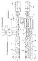
- FIG. 1 shows an embodiment of the invention, partly in a sectional view.
- FIG. 2 shows a top view of the representation according to FIG. 1, also partly in FIG Sectional view.
- the sludge is fed to the container 1 and metered from the latter to the mixing and granulating device 3 with the aid of the screw 2.
- Lime is used here as a solid, which passes from the bunker outlet 4 via a cellular wheel sluice 5 to a screw conveyor 6 and is transported by this into the mixing and granulating device 3, where the lime comes into contact with the sludge.
- the first part of the mixing and granulating device 3 consists of two intermixing mixing screws 7 and 8 and adjoining mixing paddles 9.
- the mixing and granulating device and the lime screw conveyor have a common drive 10.
- the sludge metering and screw conveyor is operated by a ge. , driven drive 11, also the rotary valve 5, so that during operation by appropriate drive controls the amount of sludge in relation to the amount of lime and finally the total amount of the materials to be mixed and granulated - exposure to the mixing and granulating device - can be varied.
Landscapes
- Chemical & Material Sciences (AREA)
- Chemical Kinetics & Catalysis (AREA)
- Organic Chemistry (AREA)
- Engineering & Computer Science (AREA)
- Life Sciences & Earth Sciences (AREA)
- Hydrology & Water Resources (AREA)
- Environmental & Geological Engineering (AREA)
- Water Supply & Treatment (AREA)
- Mechanical Engineering (AREA)
- Treatment Of Sludge (AREA)
Description
- Die vorliegende Erfindung betrifft eine Vorrichtung zum kontinuierlichen Vermischen von Schlamm, insbesondere wasserhaltigem Klärschlamm, mit einem hydratisierbaren bzw. hydraulisch abbindenden Feststoff und zum Granulieren der Mischung, im wesentlichen bestehend aus Schlamm- und Feststoffdosier- sowie Misch-und Granuliereinrichtungen für das Gemisch. Auf dem Gebiet der Abwasserbeseitigung werden zunehmend Anstrengungen vorgenommen, den anfallenden Klärschlamm entweder in eine deponierfähige festere Konsistenz zu überführen, oder aber durch Zusatz weiterer verfestigender Stoffe zu granulieren, um dann dieses Granulat als Düngemittel bzw. als Bodenverbesserungsmittel einsetzen zu können. So ist es zum Beispiel bekannt, den Klärschlamm mit gebranntem Kalk zu vermischen, wobei der Kalk durch den Wassergehalt des Klärschlamms hydratisiert wird; die Mischung erhitzt sich dabei auf Temperaturen bis zu 100° C und mehr, so dass gleichzeitig eine Hygienisierung und Pasteurisierung des Klärschlamms erfolgt. Das auf diese Weise gewonnene Erzeugnis kann daher unmittelbar und unbedenklich entweder in pulveriger Form oder als Granulat, als Bodenverbesserungsmittel bzw. als kalkhaltiger Dünger in der Landwirtschaft eingesetzt werden und belastet nicht die Deponie.
- Die technische Durchführung des oben spezifizieren Verfahrens bereitet jedoch insbesondere bei kontinuierlicher Betriebsweise eine Reihe von Schwierigkeiten, die im wesentlichen dadurch bedingt sind, dass hier Stoffe mit unterschiedlicher Konsistenz, also Schlämme einerseits und Feststoffe andererseits, mit ausreichender Dosiergenauigkeit zu mischen sind. Es kommt hinzu, dass der gebrannte Kalk mit dem Wasseranteil des Schlamms exotherm unter Bildung von Calciumhydroxid reagiert, wobei sich die Mischung vorübergehend verfestigt und wobei ferner ein Teil des Wassers aus dem Schlamm verdampft. Durch die Verfestigung der Mischung entstehen leicht Verkrustungen des Fördermittels, insbesondere im Bereich der Dosierstrecke, wodurch der kontinuierliche Materialfluss erheblich gestört wird. Auch getrennte Zuführungen mit Übergabestellen neigen zu Störungen im Materialfluss durch Verstopfung der Übergabestellen, so dass auch diese Methode nicht zum Erfolg geführt hat. Versuche in der Praxis haben weiterhin zu der Erkenntnis geführt, dass die Wassergehalte der Schlämme und auch die Konsistenz der Schlämme Schwankungen unterworfen sind.
- Als besondere Schwierigkeit bei der Durchführung der zuvor beschriebenen Verfahren hat sich jedoch herausgestellt, dass beim Einsatz von gebranntem Kalk bei dessen Zusammentreffen mit dem wasserhaltigen Schlamm erhebliche Dampfmengen entstehen, die den noch unvermischten Kalk hydratisieren und somit Störungen bei der Kalkdosierung und der Kalkzuförderung verursachen können.
- Es bestand daher die Aufgabe, eine kontinuierlich arbeitende Vorrichtung zum Vermischen und Granulieren von Schlamm mit einem Feststoff, vorzugsweise gebranntem Kalk, zu schaffen, welche sich ändernden Betriebsverhältnissen schnell und optimal angepasst werden kann und die weitgehend störungssicher ist.
- Es wurde gefunden, dass diese Aufgabe durch eine Vorrichtung gelöst werden kann, welche als Schlammdosiereinrichtung eine Förderschnecke und als Feststoffdosiereinrichtung eine Zellenradschleuse vorsieht, deren Austrag einer gesonderten Förderschnecke zugeführt wird und dass beide Förderschnecken ihr gefördertes Gut den Misch-und Granuliereinrichtungen getrennt zufördern.
- Gemäss einer vorteilhaften Ausführungsform wird im Anschluss an die Schlamm- und Feststoffdosier- und Zufördereinrichtungen eine Mischeinrichtung vorgesehen, die in ihrem ersten Teil aus einer Mischschnecke besteht.
- Es ist weiterhin vorteilhaft, wenn die erfindungsgemässe Vorrichtung im ersten Teil der Mischeinrichtung aus zwei ineinander arbeitenden Mischschnecken besteht und die Schlammdosiereinrichtung sowei die Feststoffzuführung zuförderungsmässig mit jeweils einer Mischschnecke verbunden sind.
- Besonders vorteilhaft lässt sich die erfindungsgemässe Vorrichtung gestalten durch koaxiale Anordnungen der Schlammdosiereinrichtung und der Feststoffzuführungseinrichtung mit jeweils einer Mischschnecke.
- Die Vorrichtung gemäss vorliegender Erfindung stellt sicher, dass im Bereich der Vermischungsstelle von zugeführtem Schlamm und zugeführtem Feststoff, insbesondere. wenn als Feststoff gebrannter Kalk eingesetzt wird, die Dampfentwicklung die Feststoffzuführung und -dosierung nicht beeinträchtigt. Die Ausbildung des ersten Teiles der Mischstrecke als Mischschnecke und insbesondere die bevorzugte Ausführungsform, bei welcher zwei Mischschnecken vorgesehen sind, die ineinander arbeiten, stellt sicher, dass die zugeförderten Stoffe sofort nach ihrem Eintritt in den Mischbereich nicht nur miteinander vermischt, sondern auch weitergefördert werden. Dies hatzur Folge, dass auch ein Anstauen der zugefördenen Stoffe und Verklumpungen weitgehend vermieden werden.
- An die erste Mischstrecke, die als Schneckenmischer ausgebildet ist und nur wenige Schneckenwindungen aufzuweisen braucht, schliessen sich weitere Misch- und Granuliereinrichtungen an, die zum Beispiel als Mischpaddel ausgebildet sein können und zweckmässigerweise hinsichtlich des Misch- und Granuliereffektes verstellbar auszubilden sind.
- Die Zeichnung soll die erfindungsgemässe Vorrichtung beispielhaft erläutern. Fig. 1 zeigt eine Ausführungsform der Erfindung, zum Teil in Schnittdarstellung. Fig. 2 zeigt eine Draufsicht der Darstellung gemäss Fig. 1, ebenfalls teilweise in Schnittdarstellung. Der Schlamm wird dem Behälter 1 zugeführt und aus diesem mit Hilfe der Schnecke 2 dosiert der Misch- und Granuliereinrichtung 3 zugeführt. Als Feststoff wird hier Kalk eingesetzt, welcher aus dem Bunkerauslauf 4 über eine Zellenradschleuse 5 auf eine Förderschnecke 6 gelangt und von dieser in die Misch- und Granuliereinrichtung 3 transportiert wird, wo der Kalk mit dem Schlamm in Berührung kommt. Die Misch-und Granuliereinrichtung 3 besteht in ihrem ersten Teil aus zwei ineinander arbeitenden Mischschnecken 7 und 8 sowie sich daran anschliessenden Mischpaddeln 9. Die Misch- und Granuliereinrichtung sowie die Kalkförderschnecke besitzen einen gemeinsamen Antrieb 10. Die Schlammdosier- und Förderschnecke wird durch einen ge., sonderten Antrieb 11 angetrieben, ebenfalls die Zellenradschleuse 5, so dass beim Betrieb durch entsprechende Antriebssteuerungen die Schlammenge im Verhältnis zur Kalkmenge und schliesslich auch die Gesamtmenge der zu vermischenden und zu granulierenden Stoffe - Beaufschlagung der Misch- und Granuliereinrichtung - variiert werden können.
Claims (4)
Priority Applications (1)
| Application Number | Priority Date | Filing Date | Title |
|---|---|---|---|
| AT80107417T ATE3967T1 (de) | 1980-01-07 | 1980-11-27 | Vorrichtung zum kontinuierlichen vermischen und granulieren von schlamm mit einem feststoff. |
Applications Claiming Priority (2)
| Application Number | Priority Date | Filing Date | Title |
|---|---|---|---|
| DE3000329 | 1980-01-07 | ||
| DE19803000329 DE3000329A1 (de) | 1980-01-07 | 1980-01-07 | Vorrichtung zum kontinuierlichen vermischen und granulieren von schlamm mit einem feststoff |
Publications (3)
| Publication Number | Publication Date |
|---|---|
| EP0031894A2 EP0031894A2 (de) | 1981-07-15 |
| EP0031894A3 EP0031894A3 (en) | 1981-09-30 |
| EP0031894B1 true EP0031894B1 (de) | 1983-06-29 |
Family
ID=6091609
Family Applications (1)
| Application Number | Title | Priority Date | Filing Date |
|---|---|---|---|
| EP80107417A Expired EP0031894B1 (de) | 1980-01-07 | 1980-11-27 | Vorrichtung zum kontinuierlichen Vermischen und Granulieren von Schlamm mit einem Feststoff |
Country Status (3)
| Country | Link |
|---|---|
| EP (1) | EP0031894B1 (de) |
| AT (1) | ATE3967T1 (de) |
| DE (2) | DE3000329A1 (de) |
Families Citing this family (9)
| Publication number | Priority date | Publication date | Assignee | Title |
|---|---|---|---|---|
| DE9312198U1 (de) * | 1993-08-14 | 1993-10-28 | Langbein & Engelbracht Gmbh & Co Kg, 44879 Bochum | Anordnung zur Reduzierung des Feuchtegehalts von Bioschlamm |
| DE19602452A1 (de) * | 1996-01-24 | 1997-08-07 | Zettl Gmbh & Co F | Verfahren zum Granulieren von Schlämmen |
| DE19616470A1 (de) * | 1996-04-22 | 1997-10-23 | Ruediger Schwenk | Mittel zur Konditionierung von anschließend zu entwässernden Schlämmen und Verfahren hierzu |
| DE10013664A1 (de) | 2000-03-20 | 2001-10-18 | Voest Alpine Ind Anlagen | Verfahren und Vorrichtung zum Granulieren von Schlämmen |
| DE10109771A1 (de) * | 2001-03-01 | 2002-09-05 | Schaufler Thomas | Vorrichtung zum Trocknen von Schlickstoffen |
| DE10135623A1 (de) * | 2001-07-20 | 2003-02-06 | All At Gmbh Allgaeuer Automati | Verfahren zur mechanischen und hygienischen Stabilisierung von organischen Materialien |
| CN107308830A (zh) * | 2017-07-25 | 2017-11-03 | 广西农垦糖业集团红河制糖有限公司 | 一种絮凝剂溶解稀释装置 |
| CN109761477A (zh) * | 2017-11-06 | 2019-05-17 | 北京恒净新宇环境科技有限公司 | 一种含油污泥调质系统 |
| CN113117601A (zh) * | 2021-04-02 | 2021-07-16 | 江西德弘新材料有限公司 | 一种氧化锌粉造粒机 |
Family Cites Families (1)
| Publication number | Priority date | Publication date | Assignee | Title |
|---|---|---|---|---|
| DE2239733A1 (de) * | 1972-08-12 | 1974-03-07 | Wibau Gmbh | Verfahren zur konditionierung von klaerschlamm |
-
1980
- 1980-01-07 DE DE19803000329 patent/DE3000329A1/de not_active Withdrawn
- 1980-11-27 DE DE8080107417T patent/DE3063993D1/de not_active Expired
- 1980-11-27 AT AT80107417T patent/ATE3967T1/de not_active IP Right Cessation
- 1980-11-27 EP EP80107417A patent/EP0031894B1/de not_active Expired
Also Published As
| Publication number | Publication date |
|---|---|
| DE3000329A1 (de) | 1981-07-09 |
| ATE3967T1 (de) | 1983-07-15 |
| EP0031894A2 (de) | 1981-07-15 |
| DE3063993D1 (en) | 1983-08-04 |
| EP0031894A3 (en) | 1981-09-30 |
Similar Documents
| Publication | Publication Date | Title |
|---|---|---|
| DE2548490C2 (de) | Schneckenstrangpresse | |
| DE2628916A1 (de) | Verfahren und vorrichtung zur rueckgewinnung von feinstverteilten feststoffen aus schlaemmen | |
| DE2408671A1 (de) | Verfahren und vorrichtung zum behandeln von abfaellen | |
| EP0007011B1 (de) | Vorrichtung zum kontinuierlichen Vermischen und Granulieren von Schlamm mit einem Feststoff | |
| EP0588160A1 (de) | Verfahren und Vorrichtung zur Behandlung von Abfallstoffen, insbesondere von organischen Gastronomieabfällen | |
| EP0031894A2 (de) | Vorrichtung zum kontinuierlichen Vermischen und Granulieren von Schlamm mit einem Feststoff | |
| EP0062339B1 (de) | Einrichtung zur Wiederaufbereitung von Restbeton | |
| DE2259752A1 (de) | Foerder- und mischvorrichtung, insbesondere fuer pulverige und/oder koernige massen | |
| DE2400712A1 (de) | Schleuderreaktor | |
| DE10084470T5 (de) | In einem Rohr befeuchtende Schraubenfördervorrichtung | |
| DE1905891A1 (de) | Reaktionskessel zum Hydrieren von Kalk od.dgl.und Verfahren zu seiner Regelung | |
| DE2847016A1 (de) | Anlage zur herstellung eines streufaehigen duengeproduktes | |
| DE102020130094B3 (de) | Verfahren und Vorrichtung zur Herstellung eines Ammoniumsulfat enthaltenden Düngemittel-Granulats | |
| EP1265823B1 (de) | Verfahren und vorrichtung zum granulieren von schlämmen und gegebenenfalls staubförmigem material | |
| DE2932459A1 (de) | Verfahren und vorrichtung zum loesen von feststoffteilchen in fluessigen medien | |
| EP0019052B1 (de) | Vorrichtung zum Entnehmen von Proben aus zähflüssigen Kunstharzen aus einem Behälter | |
| DE19915808B4 (de) | Verfahren und Anlage zur kontinuierlichen Aufbereitung von Wasser | |
| AT390785B (de) | Verfahren und einrichtung zur erzielung eines hohen trockengehaltes bei der entwaesserung von schlaemmen | |
| DE4008286C2 (de) | Mischvorrichtung | |
| DE20009961U1 (de) | Dosierreaktor für die Aufbereitung von Rohwasser und Anlage für die Aufbereitung von Trinkwasser | |
| DE4241977A1 (de) | Verfahren und Vorrichtung zum Entsorgen von Abfallstoffen sowie Extrusions- oder Formteil | |
| DE3228467C2 (de) | Vorrichtung zur Herstellung eines Granulats | |
| CH590076A5 (en) | Granular solids prodn. esp. sugar dissolved without clumping - by continuous flow through two mixing vessels with partial recycling | |
| DE2603771A1 (de) | Verfahren zur herstellung eines phosphathaltigen duengemittels | |
| DE2248851B1 (de) | Vorrichtung zur Herstellung einer Suspension aus Wasser und geloeschtem Kalk |
Legal Events
| Date | Code | Title | Description |
|---|---|---|---|
| PUAI | Public reference made under article 153(3) epc to a published international application that has entered the european phase |
Free format text: ORIGINAL CODE: 0009012 |
|
| AK | Designated contracting states |
Designated state(s): AT BE CH DE FR GB LU NL SE |
|
| PUAL | Search report despatched |
Free format text: ORIGINAL CODE: 0009013 |
|
| AK | Designated contracting states |
Designated state(s): AT BE CH DE FR GB LU NL SE |
|
| 17P | Request for examination filed |
Effective date: 19820312 |
|
| GRAA | (expected) grant |
Free format text: ORIGINAL CODE: 0009210 |
|
| AK | Designated contracting states |
Designated state(s): AT BE CH DE FR GB LI LU NL SE |
|
| REF | Corresponds to: |
Ref document number: 3967 Country of ref document: AT Date of ref document: 19830715 Kind code of ref document: T |
|
| REF | Corresponds to: |
Ref document number: 3063993 Country of ref document: DE Date of ref document: 19830804 |
|
| ET | Fr: translation filed | ||
| PGFP | Annual fee paid to national office [announced via postgrant information from national office to epo] |
Ref country code: LU Payment date: 19831123 Year of fee payment: 4 |
|
| PG25 | Lapsed in a contracting state [announced via postgrant information from national office to epo] |
Ref country code: LU Free format text: LAPSE BECAUSE OF NON-PAYMENT OF DUE FEES Effective date: 19831130 |
|
| PLBI | Opposition filed |
Free format text: ORIGINAL CODE: 0009260 |
|
| 26 | Opposition filed |
Opponent name: GEBRUEDER NETZSCH MASCHINENFABRIK GMBH & CO. Effective date: 19840329 |
|
| PGFP | Annual fee paid to national office [announced via postgrant information from national office to epo] |
Ref country code: CH Payment date: 19840927 Year of fee payment: 5 |
|
| PGFP | Annual fee paid to national office [announced via postgrant information from national office to epo] |
Ref country code: SE Payment date: 19840930 Year of fee payment: 5 |
|
| PGFP | Annual fee paid to national office [announced via postgrant information from national office to epo] |
Ref country code: FR Payment date: 19841130 Year of fee payment: 5 |
|
| PGFP | Annual fee paid to national office [announced via postgrant information from national office to epo] |
Ref country code: BE Payment date: 19841231 Year of fee payment: 5 |
|
| PLBN | Opposition rejected |
Free format text: ORIGINAL CODE: 0009273 |
|
| STAA | Information on the status of an ep patent application or granted ep patent |
Free format text: STATUS: OPPOSITION REJECTED |
|
| 27O | Opposition rejected |
Effective date: 19850819 |
|
| NLR2 | Nl: decision of opposition | ||
| PGFP | Annual fee paid to national office [announced via postgrant information from national office to epo] |
Ref country code: AT Payment date: 19861128 Year of fee payment: 7 |
|
| PGFP | Annual fee paid to national office [announced via postgrant information from national office to epo] |
Ref country code: NL Payment date: 19871130 Year of fee payment: 8 |
|
| PGFP | Annual fee paid to national office [announced via postgrant information from national office to epo] |
Ref country code: DE Payment date: 19881224 Year of fee payment: 9 |
|
| PG25 | Lapsed in a contracting state [announced via postgrant information from national office to epo] |
Ref country code: AT Effective date: 19891127 |
|
| PG25 | Lapsed in a contracting state [announced via postgrant information from national office to epo] |
Ref country code: SE Effective date: 19891128 |
|
| PG25 | Lapsed in a contracting state [announced via postgrant information from national office to epo] |
Ref country code: LI Effective date: 19891130 Ref country code: CH Effective date: 19891130 Ref country code: BE Effective date: 19891130 |
|
| PGFP | Annual fee paid to national office [announced via postgrant information from national office to epo] |
Ref country code: GB Payment date: 19891130 Year of fee payment: 10 |
|
| BERE | Be: lapsed |
Owner name: RHEINISCHE KALKSTEINWERKE G.M.B.H. Effective date: 19891130 |
|
| PG25 | Lapsed in a contracting state [announced via postgrant information from national office to epo] |
Ref country code: NL Effective date: 19900601 |
|
| NLV4 | Nl: lapsed or anulled due to non-payment of the annual fee | ||
| PG25 | Lapsed in a contracting state [announced via postgrant information from national office to epo] |
Ref country code: FR Effective date: 19900731 |
|
| REG | Reference to a national code |
Ref country code: CH Ref legal event code: PL |
|
| PG25 | Lapsed in a contracting state [announced via postgrant information from national office to epo] |
Ref country code: DE Effective date: 19900801 |
|
| REG | Reference to a national code |
Ref country code: FR Ref legal event code: ST |
|
| PG25 | Lapsed in a contracting state [announced via postgrant information from national office to epo] |
Ref country code: GB Effective date: 19901127 |
|
| GBPC | Gb: european patent ceased through non-payment of renewal fee | ||
| EUG | Se: european patent has lapsed |
Ref document number: 80107417.0 Effective date: 19900705 |