EP0031917A2 - Vorrichtung und Verfahren zum Herstellen einer flexiblen zylindrischen Hülse aus Mehrschichtfolien, welche aus Metall- und thermoplastischen Folien bestehen - Google Patents
Vorrichtung und Verfahren zum Herstellen einer flexiblen zylindrischen Hülse aus Mehrschichtfolien, welche aus Metall- und thermoplastischen Folien bestehen Download PDFInfo
- Publication number
- EP0031917A2 EP0031917A2 EP80107755A EP80107755A EP0031917A2 EP 0031917 A2 EP0031917 A2 EP 0031917A2 EP 80107755 A EP80107755 A EP 80107755A EP 80107755 A EP80107755 A EP 80107755A EP 0031917 A2 EP0031917 A2 EP 0031917A2
- Authority
- EP
- European Patent Office
- Prior art keywords
- mandrel
- web material
- seam
- cavity
- housing
- Prior art date
- Legal status (The legal status is an assumption and is not a legal conclusion. Google has not performed a legal analysis and makes no representation as to the accuracy of the status listed.)
- Withdrawn
Links
- 239000000463 material Substances 0.000 title claims abstract description 95
- 238000000034 method Methods 0.000 title claims description 9
- 229910052751 metal Inorganic materials 0.000 title description 3
- 239000002184 metal Substances 0.000 title description 3
- 239000004033 plastic Substances 0.000 title description 3
- 229920003023 plastic Polymers 0.000 title description 3
- 238000007789 sealing Methods 0.000 claims abstract description 19
- 238000010438 heat treatment Methods 0.000 claims description 16
- 230000007935 neutral effect Effects 0.000 claims description 14
- 239000012815 thermoplastic material Substances 0.000 claims description 5
- 230000015572 biosynthetic process Effects 0.000 claims description 4
- 239000007769 metal material Substances 0.000 claims description 2
- 238000003466 welding Methods 0.000 claims description 2
- 239000004020 conductor Substances 0.000 claims 1
- 230000002250 progressing effect Effects 0.000 claims 1
- 238000001816 cooling Methods 0.000 abstract description 5
- 229910052782 aluminium Inorganic materials 0.000 description 6
- XAGFODPZIPBFFR-UHFFFAOYSA-N aluminium Chemical compound [Al] XAGFODPZIPBFFR-UHFFFAOYSA-N 0.000 description 6
- -1 polyethylene Polymers 0.000 description 5
- 239000007795 chemical reaction product Substances 0.000 description 4
- 229920001169 thermoplastic Polymers 0.000 description 4
- 239000004416 thermosoftening plastic Substances 0.000 description 4
- 239000004698 Polyethylene Substances 0.000 description 3
- 230000006698 induction Effects 0.000 description 3
- 230000007246 mechanism Effects 0.000 description 3
- 229920000573 polyethylene Polymers 0.000 description 3
- 238000012545 processing Methods 0.000 description 3
- 239000000047 product Substances 0.000 description 3
- 238000005520 cutting process Methods 0.000 description 2
- 238000012423 maintenance Methods 0.000 description 2
- 238000004519 manufacturing process Methods 0.000 description 2
- 229920001343 polytetrafluoroethylene Polymers 0.000 description 2
- 238000003860 storage Methods 0.000 description 2
- DHKHKXVYLBGOIT-UHFFFAOYSA-N 1,1-Diethoxyethane Chemical compound CCOC(C)OCC DHKHKXVYLBGOIT-UHFFFAOYSA-N 0.000 description 1
- 229920004943 Delrin® Polymers 0.000 description 1
- 239000004593 Epoxy Substances 0.000 description 1
- 229910000831 Steel Inorganic materials 0.000 description 1
- 239000004809 Teflon Substances 0.000 description 1
- 229920006362 Teflon® Polymers 0.000 description 1
- 239000011354 acetal resin Substances 0.000 description 1
- 230000009471 action Effects 0.000 description 1
- 238000013459 approach Methods 0.000 description 1
- 230000008859 change Effects 0.000 description 1
- 239000006071 cream Substances 0.000 description 1
- 230000000694 effects Effects 0.000 description 1
- 238000012840 feeding operation Methods 0.000 description 1
- 239000011888 foil Substances 0.000 description 1
- 239000003365 glass fiber Substances 0.000 description 1
- 230000006872 improvement Effects 0.000 description 1
- 238000007689 inspection Methods 0.000 description 1
- 230000001050 lubricating effect Effects 0.000 description 1
- ISWSIDIOOBJBQZ-UHFFFAOYSA-N phenol group Chemical group C1(=CC=CC=C1)O ISWSIDIOOBJBQZ-UHFFFAOYSA-N 0.000 description 1
- 229920001568 phenolic resin Polymers 0.000 description 1
- 229920006324 polyoxymethylene Polymers 0.000 description 1
- 239000004810 polytetrafluoroethylene Substances 0.000 description 1
- 230000008569 process Effects 0.000 description 1
- 238000005096 rolling process Methods 0.000 description 1
- 238000004826 seaming Methods 0.000 description 1
- 239000010959 steel Substances 0.000 description 1
- 239000000606 toothpaste Substances 0.000 description 1
- 229940034610 toothpaste Drugs 0.000 description 1
- 238000012546 transfer Methods 0.000 description 1
Images


Classifications
-
- B—PERFORMING OPERATIONS; TRANSPORTING
- B29—WORKING OF PLASTICS; WORKING OF SUBSTANCES IN A PLASTIC STATE IN GENERAL
- B29C—SHAPING OR JOINING OF PLASTICS; SHAPING OF MATERIAL IN A PLASTIC STATE, NOT OTHERWISE PROVIDED FOR; AFTER-TREATMENT OF THE SHAPED PRODUCTS, e.g. REPAIRING
- B29C65/00—Joining or sealing of preformed parts, e.g. welding of plastics materials; Apparatus therefor
- B29C65/78—Means for handling the parts to be joined, e.g. for making containers or hollow articles, e.g. means for handling sheets, plates, web-like materials, tubular articles, hollow articles or elements to be joined therewith; Means for discharging the joined articles from the joining apparatus
- B29C65/7858—Means for handling the parts to be joined, e.g. for making containers or hollow articles, e.g. means for handling sheets, plates, web-like materials, tubular articles, hollow articles or elements to be joined therewith; Means for discharging the joined articles from the joining apparatus characterised by the feeding movement of the parts to be joined
- B29C65/7879—Means for handling the parts to be joined, e.g. for making containers or hollow articles, e.g. means for handling sheets, plates, web-like materials, tubular articles, hollow articles or elements to be joined therewith; Means for discharging the joined articles from the joining apparatus characterised by the feeding movement of the parts to be joined said parts to be joined moving in a closed path, e.g. a rectangular path
- B29C65/7882—Means for handling the parts to be joined, e.g. for making containers or hollow articles, e.g. means for handling sheets, plates, web-like materials, tubular articles, hollow articles or elements to be joined therewith; Means for discharging the joined articles from the joining apparatus characterised by the feeding movement of the parts to be joined said parts to be joined moving in a closed path, e.g. a rectangular path said parts to be joined moving in a circular path
-
- B—PERFORMING OPERATIONS; TRANSPORTING
- B29—WORKING OF PLASTICS; WORKING OF SUBSTANCES IN A PLASTIC STATE IN GENERAL
- B29C—SHAPING OR JOINING OF PLASTICS; SHAPING OF MATERIAL IN A PLASTIC STATE, NOT OTHERWISE PROVIDED FOR; AFTER-TREATMENT OF THE SHAPED PRODUCTS, e.g. REPAIRING
- B29C53/00—Shaping by bending, folding, twisting, straightening or flattening; Apparatus therefor
- B29C53/36—Bending and joining, e.g. for making hollow articles
- B29C53/38—Bending and joining, e.g. for making hollow articles by bending sheets or strips at right angles to the longitudinal axis of the article being formed and joining the edges
- B29C53/40—Bending and joining, e.g. for making hollow articles by bending sheets or strips at right angles to the longitudinal axis of the article being formed and joining the edges for articles of definite length, i.e. discrete articles
- B29C53/42—Bending and joining, e.g. for making hollow articles by bending sheets or strips at right angles to the longitudinal axis of the article being formed and joining the edges for articles of definite length, i.e. discrete articles using internal forming surfaces, e.g. mandrels
-
- B—PERFORMING OPERATIONS; TRANSPORTING
- B29—WORKING OF PLASTICS; WORKING OF SUBSTANCES IN A PLASTIC STATE IN GENERAL
- B29C—SHAPING OR JOINING OF PLASTICS; SHAPING OF MATERIAL IN A PLASTIC STATE, NOT OTHERWISE PROVIDED FOR; AFTER-TREATMENT OF THE SHAPED PRODUCTS, e.g. REPAIRING
- B29C65/00—Joining or sealing of preformed parts, e.g. welding of plastics materials; Apparatus therefor
- B29C65/02—Joining or sealing of preformed parts, e.g. welding of plastics materials; Apparatus therefor by heating, with or without pressure
- B29C65/34—Joining or sealing of preformed parts, e.g. welding of plastics materials; Apparatus therefor by heating, with or without pressure using heated elements which remain in the joint, e.g. "verlorenes Schweisselement"
- B29C65/36—Joining or sealing of preformed parts, e.g. welding of plastics materials; Apparatus therefor by heating, with or without pressure using heated elements which remain in the joint, e.g. "verlorenes Schweisselement" heated by induction
- B29C65/3604—Joining or sealing of preformed parts, e.g. welding of plastics materials; Apparatus therefor by heating, with or without pressure using heated elements which remain in the joint, e.g. "verlorenes Schweisselement" heated by induction characterised by the type of elements heated by induction which remain in the joint
- B29C65/3656—Joining or sealing of preformed parts, e.g. welding of plastics materials; Apparatus therefor by heating, with or without pressure using heated elements which remain in the joint, e.g. "verlorenes Schweisselement" heated by induction characterised by the type of elements heated by induction which remain in the joint being a layer of a multilayer part to be joined, e.g. for joining plastic-metal laminates
-
- B—PERFORMING OPERATIONS; TRANSPORTING
- B29—WORKING OF PLASTICS; WORKING OF SUBSTANCES IN A PLASTIC STATE IN GENERAL
- B29C—SHAPING OR JOINING OF PLASTICS; SHAPING OF MATERIAL IN A PLASTIC STATE, NOT OTHERWISE PROVIDED FOR; AFTER-TREATMENT OF THE SHAPED PRODUCTS, e.g. REPAIRING
- B29C65/00—Joining or sealing of preformed parts, e.g. welding of plastics materials; Apparatus therefor
- B29C65/02—Joining or sealing of preformed parts, e.g. welding of plastics materials; Apparatus therefor by heating, with or without pressure
- B29C65/34—Joining or sealing of preformed parts, e.g. welding of plastics materials; Apparatus therefor by heating, with or without pressure using heated elements which remain in the joint, e.g. "verlorenes Schweisselement"
- B29C65/36—Joining or sealing of preformed parts, e.g. welding of plastics materials; Apparatus therefor by heating, with or without pressure using heated elements which remain in the joint, e.g. "verlorenes Schweisselement" heated by induction
- B29C65/3672—Joining or sealing of preformed parts, e.g. welding of plastics materials; Apparatus therefor by heating, with or without pressure using heated elements which remain in the joint, e.g. "verlorenes Schweisselement" heated by induction characterised by the composition of the elements heated by induction which remain in the joint
- B29C65/3676—Joining or sealing of preformed parts, e.g. welding of plastics materials; Apparatus therefor by heating, with or without pressure using heated elements which remain in the joint, e.g. "verlorenes Schweisselement" heated by induction characterised by the composition of the elements heated by induction which remain in the joint being metallic
- B29C65/368—Joining or sealing of preformed parts, e.g. welding of plastics materials; Apparatus therefor by heating, with or without pressure using heated elements which remain in the joint, e.g. "verlorenes Schweisselement" heated by induction characterised by the composition of the elements heated by induction which remain in the joint being metallic with a polymer coating
-
- B—PERFORMING OPERATIONS; TRANSPORTING
- B29—WORKING OF PLASTICS; WORKING OF SUBSTANCES IN A PLASTIC STATE IN GENERAL
- B29C—SHAPING OR JOINING OF PLASTICS; SHAPING OF MATERIAL IN A PLASTIC STATE, NOT OTHERWISE PROVIDED FOR; AFTER-TREATMENT OF THE SHAPED PRODUCTS, e.g. REPAIRING
- B29C66/00—General aspects of processes or apparatus for joining preformed parts
- B29C66/004—Preventing sticking together, e.g. of some areas of the parts to be joined
- B29C66/0042—Preventing sticking together, e.g. of some areas of the parts to be joined of the joining tool and the parts to be joined
-
- B—PERFORMING OPERATIONS; TRANSPORTING
- B29—WORKING OF PLASTICS; WORKING OF SUBSTANCES IN A PLASTIC STATE IN GENERAL
- B29C—SHAPING OR JOINING OF PLASTICS; SHAPING OF MATERIAL IN A PLASTIC STATE, NOT OTHERWISE PROVIDED FOR; AFTER-TREATMENT OF THE SHAPED PRODUCTS, e.g. REPAIRING
- B29C66/00—General aspects of processes or apparatus for joining preformed parts
- B29C66/01—General aspects dealing with the joint area or with the area to be joined
- B29C66/03—After-treatments in the joint area
- B29C66/034—Thermal after-treatments
- B29C66/0342—Cooling, e.g. transporting through welding and cooling zone
-
- B—PERFORMING OPERATIONS; TRANSPORTING
- B29—WORKING OF PLASTICS; WORKING OF SUBSTANCES IN A PLASTIC STATE IN GENERAL
- B29C—SHAPING OR JOINING OF PLASTICS; SHAPING OF MATERIAL IN A PLASTIC STATE, NOT OTHERWISE PROVIDED FOR; AFTER-TREATMENT OF THE SHAPED PRODUCTS, e.g. REPAIRING
- B29C66/00—General aspects of processes or apparatus for joining preformed parts
- B29C66/01—General aspects dealing with the joint area or with the area to be joined
- B29C66/05—Particular design of joint configurations
- B29C66/10—Particular design of joint configurations particular design of the joint cross-sections
- B29C66/11—Joint cross-sections comprising a single joint-segment, i.e. one of the parts to be joined comprising a single joint-segment in the joint cross-section
- B29C66/112—Single lapped joints
- B29C66/1122—Single lap to lap joints, i.e. overlap joints
-
- B—PERFORMING OPERATIONS; TRANSPORTING
- B29—WORKING OF PLASTICS; WORKING OF SUBSTANCES IN A PLASTIC STATE IN GENERAL
- B29C—SHAPING OR JOINING OF PLASTICS; SHAPING OF MATERIAL IN A PLASTIC STATE, NOT OTHERWISE PROVIDED FOR; AFTER-TREATMENT OF THE SHAPED PRODUCTS, e.g. REPAIRING
- B29C66/00—General aspects of processes or apparatus for joining preformed parts
- B29C66/40—General aspects of joining substantially flat articles, e.g. plates, sheets or web-like materials; Making flat seams in tubular or hollow articles; Joining single elements to substantially flat surfaces
- B29C66/41—Joining substantially flat articles ; Making flat seams in tubular or hollow articles
- B29C66/43—Joining a relatively small portion of the surface of said articles
- B29C66/432—Joining a relatively small portion of the surface of said articles for making tubular articles or closed loops, e.g. by joining several sheets ; for making hollow articles or hollow preforms
- B29C66/4322—Joining a relatively small portion of the surface of said articles for making tubular articles or closed loops, e.g. by joining several sheets ; for making hollow articles or hollow preforms by joining a single sheet to itself
-
- B—PERFORMING OPERATIONS; TRANSPORTING
- B29—WORKING OF PLASTICS; WORKING OF SUBSTANCES IN A PLASTIC STATE IN GENERAL
- B29C—SHAPING OR JOINING OF PLASTICS; SHAPING OF MATERIAL IN A PLASTIC STATE, NOT OTHERWISE PROVIDED FOR; AFTER-TREATMENT OF THE SHAPED PRODUCTS, e.g. REPAIRING
- B29C66/00—General aspects of processes or apparatus for joining preformed parts
- B29C66/40—General aspects of joining substantially flat articles, e.g. plates, sheets or web-like materials; Making flat seams in tubular or hollow articles; Joining single elements to substantially flat surfaces
- B29C66/49—Internally supporting the, e.g. tubular, article during joining
-
- B—PERFORMING OPERATIONS; TRANSPORTING
- B29—WORKING OF PLASTICS; WORKING OF SUBSTANCES IN A PLASTIC STATE IN GENERAL
- B29C—SHAPING OR JOINING OF PLASTICS; SHAPING OF MATERIAL IN A PLASTIC STATE, NOT OTHERWISE PROVIDED FOR; AFTER-TREATMENT OF THE SHAPED PRODUCTS, e.g. REPAIRING
- B29C66/00—General aspects of processes or apparatus for joining preformed parts
- B29C66/70—General aspects of processes or apparatus for joining preformed parts characterised by the composition, physical properties or the structure of the material of the parts to be joined; Joining with non-plastics material
- B29C66/72—General aspects of processes or apparatus for joining preformed parts characterised by the composition, physical properties or the structure of the material of the parts to be joined; Joining with non-plastics material characterised by the structure of the material of the parts to be joined
- B29C66/723—General aspects of processes or apparatus for joining preformed parts characterised by the composition, physical properties or the structure of the material of the parts to be joined; Joining with non-plastics material characterised by the structure of the material of the parts to be joined being multi-layered
- B29C66/7232—General aspects of processes or apparatus for joining preformed parts characterised by the composition, physical properties or the structure of the material of the parts to be joined; Joining with non-plastics material characterised by the structure of the material of the parts to be joined being multi-layered comprising a non-plastics layer
- B29C66/72321—General aspects of processes or apparatus for joining preformed parts characterised by the composition, physical properties or the structure of the material of the parts to be joined; Joining with non-plastics material characterised by the structure of the material of the parts to be joined being multi-layered comprising a non-plastics layer consisting of metals or their alloys
-
- B—PERFORMING OPERATIONS; TRANSPORTING
- B29—WORKING OF PLASTICS; WORKING OF SUBSTANCES IN A PLASTIC STATE IN GENERAL
- B29C—SHAPING OR JOINING OF PLASTICS; SHAPING OF MATERIAL IN A PLASTIC STATE, NOT OTHERWISE PROVIDED FOR; AFTER-TREATMENT OF THE SHAPED PRODUCTS, e.g. REPAIRING
- B29C66/00—General aspects of processes or apparatus for joining preformed parts
- B29C66/70—General aspects of processes or apparatus for joining preformed parts characterised by the composition, physical properties or the structure of the material of the parts to be joined; Joining with non-plastics material
- B29C66/73—General aspects of processes or apparatus for joining preformed parts characterised by the composition, physical properties or the structure of the material of the parts to be joined; Joining with non-plastics material characterised by the intensive physical properties of the material of the parts to be joined, by the optical properties of the material of the parts to be joined, by the extensive physical properties of the parts to be joined, by the state of the material of the parts to be joined or by the material of the parts to be joined being a thermoplastic or a thermoset
- B29C66/739—General aspects of processes or apparatus for joining preformed parts characterised by the composition, physical properties or the structure of the material of the parts to be joined; Joining with non-plastics material characterised by the intensive physical properties of the material of the parts to be joined, by the optical properties of the material of the parts to be joined, by the extensive physical properties of the parts to be joined, by the state of the material of the parts to be joined or by the material of the parts to be joined being a thermoplastic or a thermoset characterised by the material of the parts to be joined being a thermoplastic or a thermoset
- B29C66/7392—General aspects of processes or apparatus for joining preformed parts characterised by the composition, physical properties or the structure of the material of the parts to be joined; Joining with non-plastics material characterised by the intensive physical properties of the material of the parts to be joined, by the optical properties of the material of the parts to be joined, by the extensive physical properties of the parts to be joined, by the state of the material of the parts to be joined or by the material of the parts to be joined being a thermoplastic or a thermoset characterised by the material of the parts to be joined being a thermoplastic or a thermoset characterised by the material of at least one of the parts being a thermoplastic
- B29C66/73921—General aspects of processes or apparatus for joining preformed parts characterised by the composition, physical properties or the structure of the material of the parts to be joined; Joining with non-plastics material characterised by the intensive physical properties of the material of the parts to be joined, by the optical properties of the material of the parts to be joined, by the extensive physical properties of the parts to be joined, by the state of the material of the parts to be joined or by the material of the parts to be joined being a thermoplastic or a thermoset characterised by the material of the parts to be joined being a thermoplastic or a thermoset characterised by the material of at least one of the parts being a thermoplastic characterised by the materials of both parts being thermoplastics
-
- B—PERFORMING OPERATIONS; TRANSPORTING
- B29—WORKING OF PLASTICS; WORKING OF SUBSTANCES IN A PLASTIC STATE IN GENERAL
- B29C—SHAPING OR JOINING OF PLASTICS; SHAPING OF MATERIAL IN A PLASTIC STATE, NOT OTHERWISE PROVIDED FOR; AFTER-TREATMENT OF THE SHAPED PRODUCTS, e.g. REPAIRING
- B29C66/00—General aspects of processes or apparatus for joining preformed parts
- B29C66/80—General aspects of machine operations or constructions and parts thereof
- B29C66/81—General aspects of the pressing elements, i.e. the elements applying pressure on the parts to be joined in the area to be joined, e.g. the welding jaws or clamps
- B29C66/812—General aspects of the pressing elements, i.e. the elements applying pressure on the parts to be joined in the area to be joined, e.g. the welding jaws or clamps characterised by the composition, by the structure, by the intensive physical properties or by the optical properties of the material constituting the pressing elements, e.g. constituting the welding jaws or clamps
- B29C66/8122—General aspects of the pressing elements, i.e. the elements applying pressure on the parts to be joined in the area to be joined, e.g. the welding jaws or clamps characterised by the composition, by the structure, by the intensive physical properties or by the optical properties of the material constituting the pressing elements, e.g. constituting the welding jaws or clamps characterised by the composition of the material constituting the pressing elements, e.g. constituting the welding jaws or clamps
-
- B—PERFORMING OPERATIONS; TRANSPORTING
- B29—WORKING OF PLASTICS; WORKING OF SUBSTANCES IN A PLASTIC STATE IN GENERAL
- B29L—INDEXING SCHEME ASSOCIATED WITH SUBCLASS B29C, RELATING TO PARTICULAR ARTICLES
- B29L2023/00—Tubular articles
- B29L2023/20—Flexible squeeze tubes, e.g. for cosmetics
-
- Y—GENERAL TAGGING OF NEW TECHNOLOGICAL DEVELOPMENTS; GENERAL TAGGING OF CROSS-SECTIONAL TECHNOLOGIES SPANNING OVER SEVERAL SECTIONS OF THE IPC; TECHNICAL SUBJECTS COVERED BY FORMER USPC CROSS-REFERENCE ART COLLECTIONS [XRACs] AND DIGESTS
- Y10—TECHNICAL SUBJECTS COVERED BY FORMER USPC
- Y10T—TECHNICAL SUBJECTS COVERED BY FORMER US CLASSIFICATION
- Y10T156/00—Adhesive bonding and miscellaneous chemical manufacture
- Y10T156/10—Methods of surface bonding and/or assembly therefor
- Y10T156/1002—Methods of surface bonding and/or assembly therefor with permanent bending or reshaping or surface deformation of self sustaining lamina
- Y10T156/1036—Bending of one piece blank and joining edges to form article
- Y10T156/1038—Hollow cylinder article
Definitions
- the present invention relates to an apparatus and method for fabricating cylinders from multi-ply flexible web material having outer thermo-plastic plies sandwiching a central metallic ply. More particularly, the type of flexible cylinder which the present invention is designed to produce is the type of cylinder used for the body portion of a collapsible squeeze tube such as a tooth paste tube, hair cream tube, or the like, having a central aluminum ply and outer thermo-plastic plies.
- the cylinder is formed by wrapping a piece of flexible web material into a cylindrical form and then applying heat along overlapped longitudinal edges to melt or weld together thermo-plastic plies and form a seam or seal, thereby closing the cylinder.
- Patent Number 3,959,066, which issued May 25, 1976, to the Inventors of the present invention, illustrates a prior method and device for forming a flexible cylinder from multi-ply flexible web material having plastic plies.
- the web material is cut into appropriate segments and then is fed through a longitudinal opening into a pre-form cavity wherein it is rolled approximately 360° into the form of a cylinder.
- a feed roller at the opening rotates continuously and a spring loaded pressure plate has an edge at the cavity opening which forces the web material against the feed roller to assure continuous feed. After the trailing edge of the segment of the web material has passed the edge of the pressure plate, contact between the feed roller and web material is lost and the seam of the "pre-form" is thus precisely located.
- the pre-form is longitudinally transferred into a non-conducting cylindrical forming cavity.
- Heat and pressure are applied to fuse the overlapped seam.
- Heat is applied by induction heating through the walls of the forming cavity to the aluminum ply at the overlap area.
- Pressure is applied by means of an expandible balloon mandrel inside the rolled web material.
- the balloon mandrel is collapsed and the resulting product is shrunk slightly by cooling jackets clamped around the forming cavity.
- the flexible cylindrical tube body is removed from the forming cavity on a removal mandrel that has been inserted into the flexible cylinder.
- the removal mandrel like the forming mandrel, is an expandible balloon mandrel. It is slipped in between the cylinder and the deflated forming mandrel and expands to hold and remove the cylinder.
- German Patent Application Number P2739239.8 laid open to public inspection on April 13, 1978.
- the method disclosed, in this - German Document approaches the formation of a flexible cylinder in a different manner than that disclosed in Patent Number 3,959,066, especially, in that neither forming cavities nor expandible mandrels are used.
- an appropriate length piece of flexible web material is cut and then transported to a forming station.
- the flexible web material is pressed around the bottom half of a cylindrical forming mandrel to form a U-shaped web with equal amounts of web material extending upwardly from each side of the mandrel.
- these upwardly extending portions are formed tightly around the mandrel to complete the cylinder.
- the heat sealing device can press downwardly against the mandrel and apply heat along the seam.
- the formed tube is stripped from the mandrel for further processing.
- This invention concerns the machine for the making of the cylindrical bodies that are used in flexible collapsible tubes.
- a major object of the invention is to provide such a machine which will operate at a higher speed and which will be less complex and will have fewer parts that require replacement and maintenance. These objectives in turn result in providing a less expensive cylindrical body end product.
- the multi-ply web material which is used to form the body of the collapsible squeeze tube is fed as sheet material between a cylindrical forming mandrel and a forming cavity.
- the forming cavity has a cylindrical wall that extends about 270° around. Accordingly, the housing that defines the cavity has a 90° longitudinal opening. As described below, this opening is to accomodate a seam presser..
- the forming mandrel is. mounted within the cavity coaxial of the cavity.
- Both mandrel and cavity housing are cantilever mounted at their back ends near the edge of a rotatable disk.
- the disk is used to move the forming cavity and forming mandrel from station to station through the various operations.
- the forming cavity and the forming mandrel extend forward from the face of the disk.
- the forward end of the forming cavity is open so that the formed cylindrical squeeze tube can ultimately be pushed out of the forming cavity off the forming mandrel.
- the web material is cut from a supply roll while the web material is fed between the cavity and mandrel at the infeed station position of the disk.
- the spacing between the forming mandrel and the forming cavity is slightly greater than the thickness of the web material so that- there is a loose fit, slightly looser than a slip-fit relationship, between web material and the forming surfaces of the mandrel and cavity.
- the length of web material fed into the cavity is slightly greater than the circumference of the flexible cylinder to be formed so that a longitudinal overlap zone can be formed. At this overlap zone, which in one embodiment is 1.5 mm wide, the thermoplastic material is heat sealed to form a longitudinal seam.
- the disk rotates to advance the pre-form cylinder to a heat sealing station.
- a thin longitudinal presser plate swings inward to complete the wrapping of the web.material around the mandrel and to bring and hold the longitudinal edges in the overlap position preparatory to sealing.
- This seam presser plate operates through the 90° cavity wall opening.
- the seam is sealed by radio frequency induction heating.
- a hairpin loop carrying R-F energy is in proximity to the seam and induces currents in the aluminum foil of the web material thereby generating heat and causing the adjacent polyethylene plies to weld together thereby effecting a longitudinal seal along the seam.
- the disk on which the cavity and mandrel is mounted rotates the cavity and mandrel to a stripper station where a stripper arm projects through the longitudinal opening in the cavity to contact the mandrel and then move forward across the mandrel pushing the formed squeeze tube cylinder out of the open end of the cavity housing.
- the longitudinal opening of the cavity housing has a substantial arc of, for example, about 90°.
- one longitudinal edge of the cavity housing is formed by a set of crenelations thereby establishing openings or slots through which drive disks of the feed roller at the feed station fit and through which the holding snubbers fit.
- the heating coil is a slightly arced hairpin element thereby generating a field which intercepts the outboard edges of the seam at an oblique angle. This insures a good seal along the outer edge and in particular at the corners of the seam, presumably because the oblique R-F field avoids fiel cancellation at the corners of the seam.
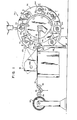
- FIG. 1 is a simplified front elevational view of the apparatus 20 of this invention.
- a multi-ply web material 22 is fed from a storage roll 24 around dancer roller 25 and associated tension rollers 26 through a feed roller 28 into a forming unit 30.
- this forming unit 30 includes a cylindrical mandrel 32 mounted within a cylindrical partial housing 34.
- the inner wall 34a of the housing 34 defines a cylindrical partial cavity, More specifically, the housing 34 has an inner wall 34a which has a cylindrical surface over an arc of approximately 270°.
- a longitudinal opening 34b in the housing 34, over an arc of approximately 90° provides, among other things access for the web 22 to be fed between mandrel 32 and housing 34.
- the mandrel 32 is mounted coaxial with the axis of the cavity defined by the housing 34. Both mandrel 32 and housing 34 are mounted at their rear end to a disk 36. Both are mounted in a cantilever fashion, the housing 34 being mounted to the disk 32 by a mounting flange 34f.
- the disk 36 contains eight of these forming units 30 equally spaced near the periphery of the disk 36.
- the disk 36 has intermittent motion in moving the forming units 30 from one processing stage to the next.
- the processing stages include the infeed stage A, the heating and sealing stage C, the cooling stages D, E and F and the stripper or removal stage G.
- Feed rollers 28 feed the web material 22 into the forming unit 30.
- the feed rollers are mounted on a shaft 28s which is driven by a chain drive mechanism (not shown).
- Feed rollers 28, shaft 28c and drive are all mounted on bracket 38.
- the bracket 38 is pivotally mounted along an axis at 38a displace from the feed rollers 28 so that the feed rollers 28 can be pivoted out of the way when the disk 26 indexes from station to station. This out of the way position for the bracket 38 and feed rollers 28 is shown in phantom in FIG. 1.
- the feed rollers 28 are mounted above the forming unit 30 in the operative condition at the infeed station A.
- the housing 34 that defines the forming cavity is separately illustrated in FIGS. 3 and 4 because an understanding of its structure will aid in understanding the relationship shown between the housing 34 and the mandrel 32 and the feed rollers 28 as well as the relationship to the presser arm 44 and stripper arm to be described further on.
- the housing 34 has a cylindrical interior wall 34a which extends about 270° around the axis of the cylinder thereby defined.
- the longitudinal opening 34b extends about 90° around that axis.
- there are a series of crenelations 40 which define a series of notches 40a through which the feed rollers 28 fit when the rollers 28 are in their operative position as shown in solid lines in FIG. 1.
- the housing 34 has an open forward end 34e and thus the housing 34 is cantilever mounted at its rear end by the flange 34f to the disk 36 (see FIG. 11).
- the web material 22 As the forward edge of the web material 22 is fed into the forming unit 30 between the mandrel 32 and housing wall 34a, the web material is deflected around the mandrel 32 within the cavity defined by the wall 34a.
- the material 22 is cut free of the supply. This may be achieved by use of a printed index on the web material 22 which is read by a conventional photo-electric switching arrangement (not shown).
- the cutting device 42 (see FIG. 6) is positioned at Station A, a predetermined short distance from the forming unit 30. When the cutting device 42 is actuated it defines the back edge of the segment of web material 22 being fed and a tab 22t of web material is left extending out of the forming unit 30. Thus, at this stage of the operation shown in FIG. 6, a partially wrapped pre-form is created.
- the tab portion 22t of the web material has to be wrapped around the mandrel 32 in order to complete the formation of the pre-form.
- the completion of the wrapping or folding around the mandrel 32 is achieved by a seam presser 44 as the forming unit 30 indexes from station B to station C.
- a seam presser 44 as the forming unit 30 indexes from station B to station C.
- the forming .unit 30 with the partially wrapped pre-form is indexed from station A to station B.
- a pair of snubbers 46 are cammed from a neutral position to a holding position by opera tion of the cam 45 on the shaft to which the snubbers 46 are mounted. Only one snubber 46 is shown in FIGS. 1 and 7 but both snubbers are shown in FIG. 11.
- the snubbers 46 extend through the notches 40a between crenelations 40 and press the web material 22 against the mandrel 32 and thus keep the partially wrapped pre-form from slipping askew or rotating within the forming unit 30. In this fashion, the position of the forward edge of the segment of web material is predetermined and fixed so that the position of the seam 22a to be formed is fixed and predetermined
- the seam presser 44 is cammed down, by the cam 45, from a neutral position against the outstanding tab 22t to fold the tab 22t around the mandrel 32 and to cause the overlapped seam 22a to be formed at station C as shown in FIG. 7.
- the seam presser 44, at station C, is in its holding position against the overlapped longitudinal edges which form the seam 22a. In this holding position, the seam presser 44 holds the seam 22a down against the mandrel 32.
- the snubbers 46 engage the web material 22 and press the partially wrapped pre-form against the mandrel 32 prior to any contact between the seam presser 44 and the web material 22. This is to assure that the seam presser 44 will not cause the material 22 to rotate or to slip, askew. Thus the snubbers 46 serve to insure that the predetermined positioning of the seam 22a is maintained so that when the pre-form is indexed to station C the seam 22a will be positioned directly under the heating coil 50.
- the forming unit 30 extends forward from the disc 36.
- a fork shaped support mechanism 62 also extends forward from the disc 36 and rotates with the disc 36.
- the snubbers 46 and the seam presser 44 are both mounted through a shaft 64 to the ends of the two arms of the fork-shaped support 62.
- the forward end 64a of the shaft to which the snubbers 46 and seam presser 44 are mounted extends into the cam slot 45a which is formed in the stationary cam plate 45.
- the camming action forces the shaft 64 radically inward or outward relative to the axis of the disc-36. Adjustment in the position of the shaft 64 is effected by causing the support 62 to rotate on its own axis thereby causing the seam presser 44 and snubbers 46 to rotate between their respective neutral and holding positions.
- an R-F generator 48 feeds radio frequency energy to a coil 50 which overlays the seam presser.44 and includes heat by R-F induction in the aluminum ply of the web material 22.
- the seam.presser 44 is non-metallic and thus transparent to the radio frequency rays generated by the R-F coil 50.
- the R-F current induced in the aluminum ply generates heat which is sufficient to cause the thermoplastic polyethylene plies to soften and flow under pressure from seam presser 44 thereby bonding or welding the overlapping plies at the seam.
- the end product cylinder 52 which has been formed by the sealing at station C cools.
- the seam presser remains in place throughout cooling stations D, E'and F in order to insure that the seam does not open while it is cooling.
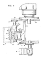
- the flexible cylinder 52 is removed from the forming unit 30 as best shown in FIG. 9.
- the snubbers 46 and the seam presser 44 have been cammed away from contact with the cylinder 52.
- a stripper 54 is moved up through the opening 34b in the housing 34 into contact with the mandrel 32 surface at a position behind the formed flexible cylinder 52. The stripper 54 then moves forward pushing the cylinder 52 out of the open front end of the forming unit 30 onto a chute which delivers the cylinder to a conveyor assembly 56 for delivery to the next state of operations.
- the stipper 54 is preferably made of Delrin (trademark of E. I. du Pont de Nemours and Co., Wilmington, Del. for acetal resin material) or other similar material.
- the upper end of stripper 54 is shaped to fit the mandrel 32.
- a pneumatic cylinder 58 pushes the stripper 54 into abutment with mandrel 32 behind the formed cylinder, near disk 36.
- the stripper 54 is then cammed to slide forward to push the flexible cylinder 52 off the mandrel 32 to be delivered to conveyor 56 for transport as required.
- a leaf spring (not shown) supports the stripper 54 on the piston rod 60 of the pneumatic cylinder 59 so as to assure a relatively gentle engagement between upper surface of stripper 54 and mandrel 32.
- the clearance between the inner wall 34a of housing 34 and the outer surface of mandrel 32 should be slightly greater than the thickness of the web material 22 to insure that the cylindrical body formed is essentially uniform and circular. If the clearance is made substantially greater, it has been found that the resulting cylindrical body is not uniformily circular and may be unacceptable for most commercial purposes. For example, where a flexible cylinder 52 having a diameter of about 27 mm is made of three ply web material 22 having a thickness of about 0.3 mm, a clearance of about 0.4 mm. between the mandrel 32 and the wall 34a has been found to give a commercially acceptable product. This means that after the web material 22 has been fed into the forming unit 30, only about 0.1 mm. of additional clearance exists on a radius. It has been found that muc less clearance results in too tight an engagement between formed cylinder 52 and mandrel 32 or housing wall 34a thereby making it difficult to remove the formed cylinder 52 from the forming unit 30.
- support structure 58 which provides support to the otherwise unsupported end of the mandrel 32.
- This support structure 58 is broken away in FIG. 1 in order to facilitate the showing of the forming unit 30.
- support structure 58 simply involves the two rigid arms shown in FIG. 1 extending into engagement with the forward end 32e of the metal core 32c. This end 32e extends forward from the rest of the mandrel 32 so as to provide this engagement with the support structure 58 and thus assure proper positioning of the mandrel 32 within the cavity formed by the housing 34 during the feeding operation at station A.
- the seam presser 44 and the forming mandrel 32 are made of non-metallic materials.
- the seam presser 44 can be formed of such synthetic plastic materials as the known epoxy glass fiber materials which combine strength with good heat resistance.
- the seam presser 44 is coated at the point of sealing with a material not subject to sticking to molten polyethylene such as polytetrafluorethylene (available under the du Pont de Nemours trademark Teflon).
- the forming mandrel 32 can be made of phenolic plastic materials covered with a layer 32a of polytetrafluoroethylene or other similar polymeric materials which can provide a lubricating and non-stick surface.
- the mandrel 32 has a steel core 32c. Although the phenolic mandrel 32 does not have to be rotatably mounted on its core 32c, it is preferably so mounted to facilitate feeding the web material 22 into the forming unit 30 by rolling as the web is fed around mandrel 32.
- FIG. 8 is a schematic view looking down, at station C, of the heating coil 50. overlaying the web material 22, The purpose of FIG. 8 is to show the geometric configuration of the heating coil 50 and its relationship to the underlying web material 22 and in particular its relationship to the seam 22a. In order to more clearly show these relationships, the seam presser 44, which lies between the coil 50 and material 22 is deleted as are the underlying mandrel 32 or surrounding housing 34.
- a collapsible and flexible cylinder 52 is made that has a length of about 135 mm., a circumference of about 85 mm. and an overlap seam 22a width of about 1.5.mm.
- the coil 50 has the approximately hairpin type of shape shown in FIG. 8.
- the coil 50 is composed of a wire that has a 4.5 mm. on a side square cross section. This wire is bent into the configuration shown. It is flat in the plane of the FIG. 8 showing but has a somewhat convex curvature facing the direction from which the preformed web material 22 is advanced.
- the positioning of the coil 50 in the horizontal plane relative to the seam 22a is not particularly critical except that the seam 22a should be fully within the main field generated by the R-F current going through the coil 50 and thus should be centered under that coil 50 somewhat as is shown in FIG. 8.
- each leg of the coil 50 should overlie the cylinder top and bottom edges 22e at an oblique angle.
- an oblique angle of 85° or, an angle a of 15°, as shown in the FIG. 8 has been found useful.
- this angular relationship near the top and bottom edges 22e of the cylinder assures that the corner of the seam 22a will heat and be sealed.
- the center portion of the legs of the coil 50 need not be so angled or particularly curved. It is only the end portions of the legs which overlie the top and bottom edges 22e of the flexible cylinder that require this angular relationship. It has been found that without this angular relationship, the corners of the seam 22a do not reliabl seal. It is believed that the reason that such occurs is that the field generated by the current in the aluminum ply tends to oppose the field generated by the coil 50 and that this opposition becomes more pronounced because of the edge effects at the edges 22e.
Landscapes
- Engineering & Computer Science (AREA)
- Mechanical Engineering (AREA)
- Physics & Mathematics (AREA)
- Thermal Sciences (AREA)
- Shaping Of Tube Ends By Bending Or Straightening (AREA)
- Laminated Bodies (AREA)
Applications Claiming Priority (2)
| Application Number | Priority Date | Filing Date | Title |
|---|---|---|---|
| US102911 | 1979-12-12 | ||
| US06/102,911 US4310369A (en) | 1979-12-12 | 1979-12-12 | Apparatus and method for fabricating a flexible cylinder from multi-ply flexible web material having metal and plastic plies |
Publications (2)
| Publication Number | Publication Date |
|---|---|
| EP0031917A2 true EP0031917A2 (de) | 1981-07-15 |
| EP0031917A3 EP0031917A3 (de) | 1984-10-24 |
Family
ID=22292357
Family Applications (1)
| Application Number | Title | Priority Date | Filing Date |
|---|---|---|---|
| EP80107755A Withdrawn EP0031917A3 (de) | 1979-12-12 | 1980-12-09 | Vorrichtung und Verfahren zum Herstellen einer flexiblen zylindrischen Hülse aus Mehrschichtfolien, welche aus Metall- und thermoplastischen Folien bestehen |
Country Status (5)
| Country | Link |
|---|---|
| US (1) | US4310369A (de) |
| EP (1) | EP0031917A3 (de) |
| JP (1) | JPS56123834A (de) |
| AU (1) | AU537318B2 (de) |
| CA (1) | CA1157753A (de) |
Cited By (2)
| Publication number | Priority date | Publication date | Assignee | Title |
|---|---|---|---|---|
| US4642083A (en) * | 1985-07-12 | 1987-02-10 | Hauni-Richmond, Inc. | Method and apparatus for making and manipulating inner tubes for use in dry cells or the like |
| EP0172252A4 (de) * | 1984-01-25 | 1988-11-02 | Toyo Seikan Kaisha Ltd | Verfahren und vorrichtung zum abdecken einer schweisszone einer senkrechten wand eines geschweissten behälters mittels eines kunststoffbandes. |
Families Citing this family (27)
| Publication number | Priority date | Publication date | Assignee | Title |
|---|---|---|---|---|
| US4366016A (en) * | 1981-06-25 | 1982-12-28 | Owens-Illinois, Inc. | Method and apparatus for producing a plastic sleeve |
| US4391666A (en) * | 1981-10-19 | 1983-07-05 | Owens-Illinois, Inc. | Container manufacturing machine |
| US4838964A (en) * | 1987-03-20 | 1989-06-13 | Xerox Corporation | Process for preparing belts |
| US4878985A (en) * | 1987-03-20 | 1989-11-07 | Xerox Corporation | Apparatus for preparing belts |
| US4968369A (en) * | 1988-10-03 | 1990-11-06 | Xerox Corporation | Belt fabrication machine |
| US5108537A (en) * | 1990-11-06 | 1992-04-28 | Owens-Brockway Glass Container Inc. | Apparatus for applying wrap-around labels to containers |
| IT1278193B1 (it) * | 1995-05-10 | 1997-11-17 | Azionaria Costruzioni Acma Spa | Metodo ed unita' per la saldatura longitudinale di involucri tubolari |
| US6612356B2 (en) * | 2001-04-10 | 2003-09-02 | Exxonmobil Oil Corporation | Apparatus for improving film machinability during film sealing |
| US20070084556A1 (en) * | 2005-10-14 | 2007-04-19 | Langseder Neal E | Method of applying a label to a squeeze tube |
| WO2012174567A2 (en) | 2011-06-17 | 2012-12-20 | Berry Plastics Corporation | Process for forming an insulated container having artwork |
| KR20140044369A (ko) | 2011-06-17 | 2014-04-14 | 베리 플라스틱스 코포레이션 | 컵용 단열 슬리브 |
| GB2539589B (en) | 2011-06-17 | 2017-04-19 | Berry Plastics Corp | Insulated container |
| GB2508777B (en) | 2011-08-31 | 2021-06-23 | Berry Plastics Corp | Polymeric material for an insulated container |
| BR112015002581A2 (pt) | 2012-08-07 | 2018-05-22 | Berry Plastics Corp | processo e máquina de formação de copos. |
| JP2015532945A (ja) | 2012-10-26 | 2015-11-16 | ベリー プラスチックス コーポレイション | 断熱容器用のポリマー材料 |
| US9840049B2 (en) | 2012-12-14 | 2017-12-12 | Berry Plastics Corporation | Cellular polymeric material |
| CN104870322A (zh) * | 2012-12-14 | 2015-08-26 | 比瑞塑料公司 | 用于形成容器毛坯的方法 |
| AR093944A1 (es) | 2012-12-14 | 2015-07-01 | Berry Plastics Corp | Troquelado para envase |
| US9957365B2 (en) | 2013-03-13 | 2018-05-01 | Berry Plastics Corporation | Cellular polymeric material |
| JP2016518289A (ja) | 2013-03-14 | 2016-06-23 | ベリー プラスチックス コーポレイション | 容器 |
| EP3039063A4 (de) | 2013-08-26 | 2017-04-12 | Berry Plastics Corporation | Polymermaterial für behälter |
| US9758655B2 (en) | 2014-09-18 | 2017-09-12 | Berry Plastics Corporation | Cellular polymeric material |
| US10513589B2 (en) | 2015-01-23 | 2019-12-24 | Berry Plastics Corporation | Polymeric material for an insulated container |
| US9937652B2 (en) | 2015-03-04 | 2018-04-10 | Berry Plastics Corporation | Polymeric material for container |
| FR3036645B1 (fr) * | 2015-05-29 | 2017-10-27 | Albea Services | Jupe de tube decoree avec une soudure laterale esthetique |
| US11214429B2 (en) | 2017-08-08 | 2022-01-04 | Berry Global, Inc. | Insulated multi-layer sheet and method of making the same |
| US20220356027A1 (en) * | 2021-05-04 | 2022-11-10 | Applied Materials, Inc. | Roller for transporting a flexible substrate, vacuum processing apparatus, and methods therefor |
Family Cites Families (18)
| Publication number | Priority date | Publication date | Assignee | Title |
|---|---|---|---|---|
| US1494993A (en) * | 1924-05-20 | coates | ||
| US1575894A (en) * | 1926-03-09 | A cobpobaxioh | ||
| US3252388A (en) * | 1966-05-24 | Tube blank including method and apparatus for fabricating tube blanks and tube bodies | ||
| US2403995A (en) * | 1946-07-16 | Method of making fiber container | ||
| US1586977A (en) * | 1925-02-11 | 1926-06-01 | Standard Johnson Company Inc | Machine for making tubular wrappers for coins, etc. |
| US2697387A (en) * | 1951-04-27 | 1954-12-21 | Daystrom Inc | Apparatus for winding tubes |
| US3505933A (en) * | 1966-12-27 | 1970-04-14 | Rissen Gmbh Maschf | Apparatus for sealing the longitudinal seam of overlapping ends of blanks for container sides of paper |
| GB1172912A (en) * | 1967-01-03 | 1969-12-03 | Cope Engineering Radcliffe Ltd | A Machine for the Manufacture of Paper Tube |
| US3510378A (en) * | 1967-03-21 | 1970-05-05 | Fmc Corp | Cylinder fabricating machine |
| GB1220581A (en) * | 1967-04-20 | 1971-01-27 | United Glass Ltd | Production of containers |
| AT291148B (de) * | 1967-12-19 | 1971-07-12 | Johannes Ihmels | Vorrichtung zum Herstellen von verschieden großen Ringen |
| US3604609A (en) * | 1968-12-02 | 1971-09-14 | Western Electric Co | Apparatus for eliminating iciclelike formations on wave-soldered connections on circuit substrates |
| US3730393A (en) * | 1969-08-28 | 1973-05-01 | Polytube | Flexible cylinder for collapsible squeeze tube |
| US3694609A (en) * | 1971-02-01 | 1972-09-26 | Owens Illinois Inc | Method and apparatus for inductive heating |
| US3952676A (en) * | 1972-11-24 | 1976-04-27 | Colgate-Palmolive Company | Dispensing container manufacturing apparatus and methods |
| DE2462343C3 (de) * | 1974-04-25 | 1985-12-05 | Owens-Illinois, Inc., Toledo, Ohio | Vorrichtung zur Herstellung einer zylindrischen Hülse aus einer thermoplastischen Folie |
| US3959066A (en) * | 1974-09-13 | 1976-05-25 | Polytube, Inc. | Apparatus for manufacturing the body portion of a collapsible squeeze tube |
| CH611223A5 (de) * | 1976-10-06 | 1979-05-31 | Karl Maegerle |
-
1979
- 1979-12-12 US US06/102,911 patent/US4310369A/en not_active Expired - Lifetime
-
1980
- 1980-12-09 EP EP80107755A patent/EP0031917A3/de not_active Withdrawn
- 1980-12-12 CA CA000366667A patent/CA1157753A/en not_active Expired
- 1980-12-12 AU AU65337/80A patent/AU537318B2/en not_active Ceased
- 1980-12-12 JP JP17475380A patent/JPS56123834A/ja active Pending
Cited By (2)
| Publication number | Priority date | Publication date | Assignee | Title |
|---|---|---|---|---|
| EP0172252A4 (de) * | 1984-01-25 | 1988-11-02 | Toyo Seikan Kaisha Ltd | Verfahren und vorrichtung zum abdecken einer schweisszone einer senkrechten wand eines geschweissten behälters mittels eines kunststoffbandes. |
| US4642083A (en) * | 1985-07-12 | 1987-02-10 | Hauni-Richmond, Inc. | Method and apparatus for making and manipulating inner tubes for use in dry cells or the like |
Also Published As
| Publication number | Publication date |
|---|---|
| AU6533780A (en) | 1981-07-23 |
| CA1157753A (en) | 1983-11-29 |
| JPS56123834A (en) | 1981-09-29 |
| US4310369A (en) | 1982-01-12 |
| EP0031917A3 (de) | 1984-10-24 |
| AU537318B2 (en) | 1984-06-14 |
Similar Documents
| Publication | Publication Date | Title |
|---|---|---|
| US4310369A (en) | Apparatus and method for fabricating a flexible cylinder from multi-ply flexible web material having metal and plastic plies | |
| US4121402A (en) | Methods and means for manufacturing foam plastic containers and sidewall blanks for same | |
| US4306849A (en) | Apparatus for providing bottom blanks for containers in a manufacturing process | |
| US4365460A (en) | Method and apparatus for manufacturing foam plastic containers by use of a tubular forming mandrel | |
| US4366016A (en) | Method and apparatus for producing a plastic sleeve | |
| US3764425A (en) | Apparatus and method for the manufacture of tubular containers | |
| CA1100399A (en) | Method of and device for fabricating plastic sleeves | |
| US4070513A (en) | Heat seal apparatus and seamed sleeve article made thereby | |
| NL8006021A (nl) | Inrichting voor het vormen van buisvormige kunst- stofhulzen voor aanbrenging op flessen. | |
| US4054474A (en) | Shrink wrapping | |
| US4391666A (en) | Container manufacturing machine | |
| JPH0353056B2 (de) | ||
| US3942298A (en) | Method of and apparatus for packaging an annular object | |
| US5415721A (en) | Apparatus for forming and applying a shrinkable sleeve on a container | |
| US4285750A (en) | Method for producing a plastic sleeve | |
| US4559765A (en) | Apparatus for manufacturing foam plastic containers by use of a tubular forming mandrel | |
| NL8301658A (nl) | Inrichting voor het produceren van buisvormige omhulsels van kunststof, die om houders worden aangebracht. | |
| US2795263A (en) | Apparatus for applying tape to containers | |
| US3922834A (en) | Apparatus for closing of wrapping bags or sleeves | |
| US3959066A (en) | Apparatus for manufacturing the body portion of a collapsible squeeze tube | |
| CA1069422A (en) | Method of producing a container and apparatus herefor | |
| US4645480A (en) | Method and apparatus for fabricating nestable thermoplastic containers | |
| US4170927A (en) | Apparatus for depositing lengths of foil material | |
| EP0004971A1 (de) | Einrichtung und Verfahren zum Herstellen von rohrförmigen Gegenständen | |
| EP0103027B1 (de) | Verfahren und vorrichtung zur herstellung von metalldosen |
Legal Events
| Date | Code | Title | Description |
|---|---|---|---|
| PUAI | Public reference made under article 153(3) epc to a published international application that has entered the european phase |
Free format text: ORIGINAL CODE: 0009012 |
|
| AK | Designated contracting states |
Designated state(s): AT BE CH DE FR GB IT NL SE |
|
| PUAL | Search report despatched |
Free format text: ORIGINAL CODE: 0009013 |
|
| AK | Designated contracting states |
Designated state(s): AT BE CH DE FR GB IT LI NL SE |
|
| STAA | Information on the status of an ep patent application or granted ep patent |
Free format text: STATUS: THE APPLICATION IS DEEMED TO BE WITHDRAWN |
|
| 18D | Application deemed to be withdrawn |
Effective date: 19850625 |
|
| RIN1 | Information on inventor provided before grant (corrected) |
Inventor name: MILLER, WILLIAM PATRICK Inventor name: TWIGG, ROBERT WAYNE |