EP0032045A2 - Steuersystem zum Anhalten der Spindel in einer vorbestimmten Drehposition - Google Patents
Steuersystem zum Anhalten der Spindel in einer vorbestimmten Drehposition Download PDFInfo
- Publication number
- EP0032045A2 EP0032045A2 EP80304696A EP80304696A EP0032045A2 EP 0032045 A2 EP0032045 A2 EP 0032045A2 EP 80304696 A EP80304696 A EP 80304696A EP 80304696 A EP80304696 A EP 80304696A EP 0032045 A2 EP0032045 A2 EP 0032045A2
- Authority
- EP
- European Patent Office
- Prior art keywords
- spindle
- speed
- signal
- motor
- rotational position
- Prior art date
- Legal status (The legal status is an assumption and is not a legal conclusion. Google has not performed a legal analysis and makes no representation as to the accuracy of the status listed.)
- Granted
Links
Images


Classifications
-
- G—PHYSICS
- G05—CONTROLLING; REGULATING
- G05B—CONTROL OR REGULATING SYSTEMS IN GENERAL; FUNCTIONAL ELEMENTS OF SUCH SYSTEMS; MONITORING OR TESTING ARRANGEMENTS FOR SUCH SYSTEMS OR ELEMENTS
- G05B19/00—Program-control systems
- G05B19/02—Program-control systems electric
- G05B19/18—Numerical control [NC], i.e. automatically operating machines, in particular machine tools, e.g. in a manufacturing environment, so as to execute positioning, movement or co-ordinated operations by means of program data in numerical form
- G05B19/19—Numerical control [NC], i.e. automatically operating machines, in particular machine tools, e.g. in a manufacturing environment, so as to execute positioning, movement or co-ordinated operations by means of program data in numerical form characterised by positioning or contouring control systems, e.g. to control position from one programmed point to another or to control movement along a programmed continuous path
- G05B19/39—Numerical control [NC], i.e. automatically operating machines, in particular machine tools, e.g. in a manufacturing environment, so as to execute positioning, movement or co-ordinated operations by means of program data in numerical form characterised by positioning or contouring control systems, e.g. to control position from one programmed point to another or to control movement along a programmed continuous path using a combination of the means covered by at least two of the preceding groups G05B19/21, G05B19/27 and G05B19/33
-
- G—PHYSICS
- G05—CONTROLLING; REGULATING
- G05B—CONTROL OR REGULATING SYSTEMS IN GENERAL; FUNCTIONAL ELEMENTS OF SUCH SYSTEMS; MONITORING OR TESTING ARRANGEMENTS FOR SUCH SYSTEMS OR ELEMENTS
- G05B2219/00—Program-control systems
- G05B2219/30—Nc systems
- G05B2219/41—Servomotor, servo controller till figures
- G05B2219/41021—Variable gain
-
- G—PHYSICS
- G05—CONTROLLING; REGULATING
- G05B—CONTROL OR REGULATING SYSTEMS IN GENERAL; FUNCTIONAL ELEMENTS OF SUCH SYSTEMS; MONITORING OR TESTING ARRANGEMENTS FOR SUCH SYSTEMS OR ELEMENTS
- G05B2219/00—Program-control systems
- G05B2219/30—Nc systems
- G05B2219/41—Servomotor, servo controller till figures
- G05B2219/41358—Transmission, variable gear ratio
-
- G—PHYSICS
- G05—CONTROLLING; REGULATING
- G05B—CONTROL OR REGULATING SYSTEMS IN GENERAL; FUNCTIONAL ELEMENTS OF SUCH SYSTEMS; MONITORING OR TESTING ARRANGEMENTS FOR SUCH SYSTEMS OR ELEMENTS
- G05B2219/00—Program-control systems
- G05B2219/30—Nc systems
- G05B2219/49—Nc machine tool, till multiple
- G05B2219/49273—Switch between continuous drive and index or stop mode
Definitions
- This invention relates to a control system for stopping a spindle at a predetermined rotational position.
- a key is provided on the spindle of the machine tool and a keyway is formed in each of the various tools that are employed.
- the spindle In order to mate the spindle and tool with each other smoothly, the spindle must be positioned and stopped accurately in such a manner as to bring the key and keyway into perfect alignment.
- machine tools for cutting work, and for boring work there is a similar requirement in machine tools for cutting work, and for boring work in particular.
- the present inventors have already proposed a system for stopping a specified point on spindle at a predetermined rotational position through purely electrical means without relying upon a mechanical brake or the like.
- the proposed system succeeds in stopping the spindle with a high degree of accuracy, a considerable amount of time may be required to accomplish this if the speed change ratio between the spindle and the spindle driving motor is high. This naturally results in a poorer working efficiency.
- a speed change mechanism such as a gear mechanism between the motor and spindle so that machining can be performed while switching between a high gear setting (reduction ratio low) and a low gear setting (reduction ratio high).
- the high gear setting is used for the light machining of wood or light metals such as aluminum, whereas the low gear setting is employed for the heavy machining of steel or the like.
- the control mode for stopping the spindle begins after the generation of a signal for one spindle revolution, with the specified point on the spindle being stopped correctly at the predetermined position after the one revolution.
- the gear ratio between the spindle and motor is set to high gear (1:1) to enable the spindle to be stopped after a single revolution of the motor.
- the motor-to-spindle ratio is typically 4:1, four revolutions of the motor are required to bring the spindle to a stop.
- the time required for the stopping operation in low gear is at least four times that of high gear, so that the proportion of time spent for actual machining work decreases. The inevitable result is a decline in working efficiency.
- the low gear setting allows the motor speed to be increased in comparison with the speed under a high gear setting.
- a control system for stopping a spindle at a predetermined rotational position, for driving a spindle through a speed change mechanism in such a manner that a positional deviation between the present rotational position of a specified point on the spindle and a predetermined rotational position at which the specified point is to be stopped, is reduced to zero, thereby to stop the specified point on the spindle at the predetermined rotational position,
- control system is characterized.in that, in operation thereof, a positioning gain obtained by dividing the speed of the spindle motor by an amount of motor rotation which depends upon the positional deviation of the spindle, is so controlled as to remain substantially constant regardless of the speed change ratio established between the spindle motor and spindle by said speed change mechanism, thereby to stop the specified point on the spindle at the predetermined rotational position.
- Fig. 1 to describe positioning gain as well as the principle of the present invention.
- Figs. lA and 1B are illustrative views of high and low gear situations, respectively.
- Fig. 1A shows that, in a high gear setting, a spindle is rotating at a predetermined speed until a time t 1 since the particular machine tool is performing cutting work or the like up to this time.
- the rotational speed of the spindle is reduced and reaches a preset speed V H at time t 2 .
- the spindle rotates at.this speed until the generation of a signal for one spindle revolution, as will be described later. If this signal is generated at time t 3 , a spindle control operation for stopping the spindle begins at this point until, at time t 4 , a specified point on the spindle is stopped at the predetermined position.
- Fig. 1B which shows the conditions for low gear
- the rotational speed of the spindle is reaucea ana reacnes a preset speea v L at time t 2 ' following the issuance of the orientation command at time t l .
- the spindle rotates at the preset speed until the generation of the signal for one spindle revolution. If this signal is generated at time t 3 ', a spindle control operation for stopping the spindle begins at this point until, at time t 4 ', a specified point on the spindle is stopped at the predetermined position.
- the period of time from the generation of the one revolution signal until the completion of the spindle stopping control operation will be at least four times longer in low gear than in high gear. Accordingly, if the value of V L is set to be four times that of V H , it may be presumed that the time required to stop the spindle in low gear can be made equal to that required to accomplish the same in high gear. This means making the positioning gain in high gear the same as that in low gear where the positioning gain during the spindle stopping control operation is defined by V/8.
- V represents the speed of the motor in radians per second, while 0, also measured in radians, represents the amount through which the spindle motor rotates until a positional deviation, between a specified point on the spindle and a predetermined rotational position, is reduced to zero.
- Tnus, tne positioning gain V/ ⁇ is generally represented by dividing a command speed by a positional deviation measured from a predetermined stopping position. If we let n H represent the number of motor revolutions needed to revolve the spindle once in high gear, and let n L represent the number of motor revolutions needed to revolve the spindle once in low gear, then the positioning gain PG(H) for high gear and the positioning gain PG(L) for low gear at the time of a control operation for stopping the spindle at the predetermined rotational position, will be expressed by the following:
- an arrange- may be ment in accordance with the present invention / so adapted that the gain of the positioning control system can be changed in both high and low gear when the spindle is being subjected to positioning control to stop it at the predetermined position.
- Fig. 2 shows a block diagram of a spindle control apparatus to which the present invention may be applied.
- a speed command circuit 1 for producing a speed command CV
- an orientation command circuit 2 for producing an orientation command ORCM.
- a speed control circuit 3 includes an adder 3a, a phase compensating circuit 3b connected to the output of the adder, a voltage-to-phase converter 3c connected to the output of the phase compensating circuit, and a thyristor converter 3d connected to the output of the converter 3c.
- the adder 3a is adapted to deliver a difference voltage, representative of a speed deviation, between the voltage of the speed command CV and the voltage of an actual speed signal, during a speed control operation, and to deliver a difference voltage between a rotational position deviation RPD and the actual speed AV.
- the phase compensating circuit 3b subjects the output voltage of the adder 3a to a phase compensation by advancing or retarding its phase.
- the voltage-to-phase converter 3c controls the firing angle of each thyristor in the thyristor circuit 3d in accordance with the output voltage of the phase compensating circuit 3b.
- the thyristor converter 3d operates in accordance with the controlled firing angles of its thyristors to convert the three-phase voltage from a three-phase power supply 3e into a direct current to vary the value of the voltage applied to a DC motor which will be described later, thereby to regulate the speed at which the motor rotates.
- the DC motor is designated at numeral 4 and serves as a spindle drive motor.
- a tachometer generator 5 As the DC motor 4 rotates, a tachometer generator 5 generates a voltage in accordance with the motor speed.
- the rotational motion of the DC motor 4 is transmitted through a gear mechanism & to a spindle 7.
- the gear mechanism 9 is capable of being changed over to high or low gear by means of an externally applied changeover signal.
- a rotational position sensor 10 is adapted to detect the rotational position of the spindle 7 and comprises a magnetic body 10a which is attached to the spindle 7, a sensing portion 10b which is attached to a stationary portion of the machine such as the spindle bearing portion so as to confront the magnetic body 10a, and an electrical circuit 10c, as shown in Figs. 3A and 3B.
- the position sensor 10 produces a fine position deviation.signal DV 2 and an approach signal ASV, shown in Fig. 3C, which vary in accordance with the rotational deviation of the spindle 7 with respect to a predetermined rotational position OS at which a specified point on the spindle is to be stopped.
- an orientation control circuit 11 includes a rotational position deviation signal generating circuit lla which receives the fine position deviation signal DV 2 , the approach signal ASV, and the signal AV, indicative of the actual speed of the spindle, provided by the tachometer 5, and which produces the rotational position deviation signal RPD which serves as a spindle speed command signal when an operation for stopping the spindle at the predetermined rotational position is being carried out, an orientation completion signal ORDEN, and a signal VSR indicating that the prescribed speed has been reached.
- the orientation control circuit 11 includes also a loop changeover circuit llb for actuating a loop changeover switch 12 on the basis of the orientation command signal ORCM from the orientation command circuit 2 and the signal VSR from the position deviation signal generating circuit lla.
- FIG. 3A showing a front view
- Fig. 3B a plan view for a case in which the magnetic body -10a is mounted on the spindle 7.
- the magnetic body 10a is so mounted on the spindle 7 that the center of the magnetic body 10a will coincide with the center of the sensing portion 10b when a specified point on the spindle is located at the predetermined rotational position at which said point is desired to be stopped.
- the magnetic body 10a as shown in Fig. 4A, has magnets l0a", 10a"', possessed of a triangular cross-section, mounted in a case 10a' in such a manner than the intensity of the magnetic field changes from S to N in the direction of spindle rotation, i.e., in the direction of the arrow.
- the sensing portion 10b is mounted on a mechanically stationary portion of the machine so as to confront the magnetic body 10a, and includes three saturable reactors SRA 1 , SRA 2 , SRA 3 provided in a case lOb' and aligned in the direction of spindle rotation, as shown in Fig. 4A.
- Each of the saturable reactors comprises coils L 1 , L 2 wound on a core CR, as shown in Fig. 4B.
- the coils L l , L 2 on each core have the same number of turns and are wound in opposite directions.
- the coils on each core share a common terminal TA to which a high-frequency signal is applied, and signals which are in accordance with the rotational position of the magnetic body 10a are obtained from the terminals TB, TC of respective coils.
- Included in the electrical circuit 10c is a circuit shown in Fig. 5, associated with a corresponding one of the saturable reactors SRA for processing the signal produced by the reactor.
- Included in the electrical circuit 10c are a pulse oscillator OSC for generating a 100kHz high-frequency signal, an isolating transformer ITR, and half-wave rectifiers HWR 1 , HWR 2 .
- the saturable reactor SRA is excited by the high-frequency pulse signal HFP through the intermediary of the isolating transformer ITR.
- an analog output voltage is obtained across the terminals a, b of the circuit, which output voltage is proportional to the external magnetic field H ex t whose strength varies in accordance with the rotational position of the magnetic body 10a.
- the action of the analog output voltage which is obtained across the terminals a, b and which depends upon the rotational deviation of the spindle 7 will be described in connection with the centrally located reactor SRA 2 shown in Fig. 4A.
- the high-frequency pulse signal HFP acts about the vertical zero line of the reactor B-H curve as its center, as shown in Fig. 9A.
- the number of lines of flux cutting the coils L 1 , L 2 are equal, so that the output voltages.from the terminals TB, TC are equal in amplitude but displaced in phase by 180 degrees.
- each saturable reactor SRA has a hysteresis characteristic which is so small as to be negligible. Since the voltages from the terminals TB, TC are rectified by the respective half-wave rectifiers HWR 1 , HWR 2 , the potentials at the terminals a, b are equal, so that the voltage across a, b is zero. Now, as the spindle 7 rotates and the magnetic body 10a approaches the centrally located saturable reactor SRA 2 , the external magnetic field H ex t being generated by the magnetic body begins to act upon the saturable reactor SRA 2 .
- h l denote the field generated by the high-frequency pulse signal H FP
- a flux in accordance with h l - H ext will cut the coil L l
- a flux in accordance with h t + H ex t will cut the coil L 2 .
- the high-frequency pulse signal HFP will act about the line -H ex t as its center with respect to the coil L 1 , as shown in Fig. 6C, and about the line +H ex t with respect to the coil L 2 , as depicted in Fig. 6D.
- the negatively directed flux which cuts the coil L 1 causes saturation of the core so that there is a smaller amount of variation
- the negatively directed flux which crosses the coil L 2 does not cause saturation so that there is a greater amount of variation.
- the induced voltage e takes on the value (where N is the number of turns)
- the potential at the terminal b will become greater than the potential at terminal a, giving rise to a potential difference across the terminals.
- This potential difference will vary in the manner of the fine position deviation signal DV 2 of Fig. 4C and, as the magnetic body 10a continues to rotate, will become zero when the center of the magnetic body 10a coincides with the center line of the saturable reactor SRA 2 .
- the result is an analog voltage signal having maximum and minimum values.
- This potential difference also defines an analog voltage signal, similar to that of the fine position deviation signal DV 2 , having maximum and minimum values.
- the analog voltage signals associated with the reactors SRA 1 , SRA 3 also depend upon the rotation of the magnetic body 10a on the spindle 7.
- the electrical circuit 10c of the position sensor 10 further includes a conversion circuit for producing a signal DV 3 , shown in Fig. 4C, by subjecting to a 180-degree phase conversion the analog voltage signal which is obtained from the saturable reactor SRA 3 and which varies in accordance with the rotational movement of the magnetic body 10a, and a circuit which produces the approach signal ASV, also shown in Fig. 4C, by adding together the signal DV 3 and the analog voltage signal, denoted by DV 1 , which is obtained from the saturable reactor SRA 1 and which varies in accordance with the rotational movement of the magnetic body 10a.
- the approach signal ASV indicates that a specified point on the spindle 7 has reached an area in the environs of the predetermined rotational position.
- the rotational position deviation signal generating circuit lla receives the fine position deviation signal DV 2 and the approach signal ASV from the position sensor 10, and the actual speed signal AV from the tachometer 5.
- the signal AV is integrated within the circuit 11a, and the output signal resulting from the integration operation is subtracted from a yet to be described initially set voltage ISV (-Vi when the spindle is rotating in the forward direction, and +V i when the spindle is rotating in the reverse direction).
- the signal AV is converted into a coarse position deviation signal CPD.
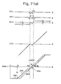
- the initially set voltage ISV and a bias signal BIS shown in Fig. 7A, are formed within the rotational position deviation signal generating circuit lla.
- the voltage value Vi of the voltage ISV has been set so as to be equal to a rotational position deviation which corresponds to one revolution (360°) of the spindle in the case of the high gear setting.
- the speed command CV attains a voltage corresponding to the speed V H at which the spindle stopping mode begins as shown in Fig. 1A for the high gear condition, or attains a voltage corresponding to the speed V L at which the spindle stopping mode begins as shown in Fig. 1B for the low gear condition. Accordingly, when the rotational speed of the spindle 7 falls and reaches the command speed, the signal VSR, indicating that the prescribed speed has been reached, goes to logical "1".
- the rotational position deviation signal generating circuit lla produces the initially set voltage ISV from the time that the signal VSR goes to logical "1" until the time t 2 at which the spindle initially reaches the predetermined rotational position.
- the initially set voltage ISV will, of course, differ between the low and high gear settings. For example, it is obvious that ISV will correspond to V H in the high gear condition and to v L in the low gear condition. Furthermore, it will be assumed that the spindle is rotating in the forward direction at the time that it is to be stopped at the predetermined rotational position.
- the coarse position deviation signal CPD whose polarity will be negative, is produced until the magnetic body 10a draws near to the area NCP (defined between -8 1 and + ⁇ 1 ) in the environs of the predetermined rotational position, that is, until it arrives at the position -8 2 .
- the bias signal BIS is produced until the abovementioned area N CP is reached.
- the fine position deviation signal DV 2 is generated after the magnetic body 10a has reached and entered the area NCP in the environs of the predetermined rotational position.
- the changeover switch 12 is connected to the a side in Fig. 2, thereby forming a speed control loop.
- the adder 3a receives the speed command signal CV and the average speed signal AV from the tachometer 5, and responds by delivering a rotational speed deviation voltage.
- the voltage-to-phase converter 3c controls the firing angle of the thyristors in the thyristor converter 3d in accordance with the speed deviation voltage, the thyristor converter 3d thereby regulating the voltage applied to the DC motor 4.
- the speed control loop regulates the speed of the motor so as to rotate the spindle at approximately the commanded speed.
- a control device such as a numerical control device, instructs the orientation command circuit 2 to apply the orientation command signal ORCM to the loop changeover circuit llb at the time tg to place this circuit in the set state.
- the orientation command signal ORCM is applied to the speed command circuit 1, so that the speed command CV attains a voltage corresponding to V H or V L .
- the actual speed of the spindle consequently decreases and follows the speed command CV.
- the signal VSR is generated within the position deviation signal generating circuit lla, and causes the loop changeover circuit llb to changeover the switch 12 to the side b, so that circuit operation now changes from speed control to position control.
- the position deviation signal generating circuit lla produces first the initially set voltage ISV in response to the signal VSR. As a result, the spindle continues to rotate at the constant speed V H or V L even when the control loop is switched over. As the magnetic body 10a continues to rotate and reaches the predetermined rotational position for the first time (time t 2 ), the rotational position deviation signal generating circuit lla begins generating the coarse position deviation signal CPD. As the spindle continues to rotate and the magnetic body 10a approaches the area in the environs of the predetermined rotational position (time t 3 ), the position deviation signal generating circuit lla produces the bias signal BIS.
- the fine position deviation signal DV 2 starts being generated.
- the signal DV 2 has decreased to zero, namely when the central portion of the magnetic body (the specified point on the spindle) is directly confronting the central portion of the saturable reactor SRA 2 , the spindle stops rotating. This completes positioning control of the spindle.
- a circuit 101 is provided to form the initially set voltage ISV and the bias signal BIS, to integrate the actual speed voltage signal AV, and to subtract the output voltage, resulting from the integration operation, from the initially set voltage ISV.
- a changeover switch SW is switched over to either a +15 volt side or a -15 volt side in accordance with the direction of spindle rotation. If the spindle is rotating in the forward direction, the connection is to the -15 volt side.
- This voltage is divided by resistors r l , r 2 , and a capacitor C is charged through an amplifier AMP 1 , a resistor r 4 and a switch S 9 , the voltage charged in the capacitor becoming the value Vi of the initially set voltage ISV.
- the capacitor C discharges at the time constant RC since the voltage value of the actual speed signal AV is lower than Vi, and the coarse position deviation signal CPD, obtained due to the subtraction of the output voltage, obtained by integrating the actual speed signal AV, from the initially set voltage ISV, appears at the output of the amplifier AMP 2 .
- the amplifier AMP 2 ,. resistor R and capacitor C form an integration circuit. If the switches S 9 , S 10 are closed after the voltage of.the signal CPD reaches a specified value V j , the circuit 101 acts as an amplifier, and the bias signal BIS at the specified level V j is obtained at the output of the amplifier AMP 2 . In other words, in accordance with the particular combination and timing of the opening and closing operation of the switches S 7 through S 10 , first the initially set voltage ISV is delivered, then the coarse position deviation signal CPD, and finally the bias signal BIS.
- Numerals 102, 103 denote changeover circuits for of the positioning control system switching gain/in accordance with gear ratio. These circuits are operable to set the positioning gain of the position control loop high when the gears between the DC motor 4 and spindle 7 are set low. Specifically, switches S 7 , S 2 are closed to raise the gain in the case of low gear, and switches Sg, S 3 are closed to lower the gain in the case of high gear.
- the gain changeover circuit 103 includes an analog adder AAD, a variable resistor VR 1 for adjusting the gain of the adder, a variable resistor VR 2 for dividing the output voltage of the adder AAD and for adjusting the dividing ratio, variable resistors VR 1 ', VR 2 ' for adjusting spindle stopping position, and switches S 2 , S 3 .
- Variable resistor VR 1 is for adjusting positioning gain for the low gear setting
- variable resistor VR 2 is for adjusting positioning gain for the high gear setting.
- the variable resistors VR 1 ', VR 2 ' are employed when adjusting the stopping position of the spindle.
- variable resistors VR 1 ', VR 2 ' are provided in order to correct for this shift in stopping position.
- changing over the gain by means of the changeover circuits 102, 103 permits the amplitude of the rotational speed deviation voltage RPD, obtained from the output terminal OUT, to be made several times larger in low gear than the amplitude in high gear.
- RPD rotational speed deviation voltage
- Denoted at 104 is a well-known absolute value circuit which takes the absolute value of the output from the circuit 101.
- a comparator 105 detects whether or not the coarse position deviation signal CPD has fallen below a predetermined level, and produces a signal NRPS which indicates that the predetermined portion (the magnetic body 10a) has drawn near the area NCP in the environs of the predetermined rotational stopping position.
- the signal NRP S closes the switches S 91 S 10 .
- a gain adjustment circuit 106 adjusts the gain in accordance with the gap between the magnetic body 10a and the sensing portion lOb, and produces the detection voltage DV 2 (the fine position deviation voltage) having a prescribed slope.
- a slicer circuit 107 slices the approach signal ASV at a predetermined level and produces a signal LS which indicates that the magnetic body has reached the area in the environs of the.predetermined rotational position. The signal LS opens the switches 5 5 , S 6 and closes switch S 4 . As a result, the fine position deviation signal DV 2 is delivered as the deviation signal.
- a forward-reverse changeover circuit 108 has its switch S 5 closed in a case where the spindle is controlled by rotating it in the forward direction, and its switch S 6 closed in a case where the spindle is controlled by rotating it in the reverse direction.
- An "in-position" signal generating circuit 109 comprising a comparator, monitors the fine position deviation signal DV 2 and generates the in-position signal INPOS when the spindle is within range of the predetermined rotational position. Thereafter a signal indicating completion of the orientation operation is sent to the numerical control unit.
- Comparators 110, 111 monitor the fine position deviation signal DV 2 and produce signals NEG, POS upon detecting whether the spindle is approaching the predetermined rotational direction while rotating in the reverse direction (signal NEG at logical "I") or while rotating in the forward direction (signal POS at logical "1"), respectively.
- One of the switches S 5 , S 6 will be closed and the other will be opened by the signals VSR and LS depending upon which of the signals NEG, POS is a "1".
- the analog adder AAD of the gain changeover circuit 103 delivers either the fine position deviation signal or the coarse position deviation signal in accordance with the open or closed state of the switch S 4 , S 5 or S 6 .
- a speed detection circuit 113 receives the voltage AV indicative of the actual speed of the spindle and, in the high or low gear condition, generates the signal VSR when the actual speed reaches the prescribed speed, and delivers a speed zero signal VZR when the actual speed reaches zero.
- An orientation completion signal generating circuit 114 receives the in-position signal INPOS, the zero speed signal VZR, and the orientation command signal ORCM, and takes the logical product of these signals. In other words, the orientation completion signal ORDEN is delivered when INPOS, VZR and ORCM are all at logical "1".
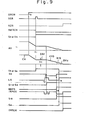
- the orientation command signal ORCM goes to logical "1" at time to, the voltage indicative of the command speed CV decreases, and so does the actual speed AV, with AV becoming Vi at time t l .
- the signal VSR indicative of the fact that the specified speed has been reached, goes to logical "1"
- switch 12 is changed over , one of the switches S 2 , S 3 is closed in accordance with the low/high setting of the gears, and one of the switches S 51 S 6 is closed in accordance with the direction, either forward or reverse, of spindle rotaticn.
- the DC motor continues rotating at a constant speed corresponding to Vi or to K ⁇ V i and the spindle reaches the predetermined rotational position the first time (i.e., the signal LS is a "1", and the signal INPOS is a "1").
- switch S 9 is opened and one of the switches S 7 , S 8 is closed in accordance with the low/high setting.of the gears. Therefore the coarse position deviation signal CPD is obtained from the changeover switch 12.
- the comparator 105 issues the signal NRPS (logical "1"), whereby the switches S 9 , S 10 are closed.
- the bias signal BIS of the prescribed level is delivered from the changeover switch 12.
- the signal LS goes to the "1" level, switches S 5 1 S 6 are opened, and switch S 4 is closed.
- the fine position deviation signal DV 2 is delivered from the changeover switch 12.
- the in-position signal INPOS is generated. This is followed by the actual speed of the spindle falling to zero, whereupon the zero speed signal VZR goes to logical "1". This completes the control operation for stopping the spindle at the predetermined rotational position, the orientation completion signal ORDEN being delivered from the orientation completion signal generating circuit 114.
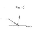
- the shaded portion in Fig. 10 represents a threshold region within which overshooting does not occur.
- the solid line representats a case in which the positioning gain exceeds the threshold ,in the vicinity of the command value, and the broken line represents a case in which the position-' ing gain does not exceed the threshold in the vicinity of the command value. Overshooting occurs in the former case but not in the latter. It follows then that the foregoing should be considered when setting the positioning gain.
- the positioning gain can be held constant regardless of the high or low gear setting, thereby enabling a marked reduction in the time needed to achieve positioning of the spindle at the predetermined location under a low gear condition. This in turn permits an increase in the proportion of time actually used for machining, so that working efficiency can be enhanced.
- the arrangement is such that a position deviation signal for guiding the spindle to said position is applied as an input signal to a speed control loop for controlling spindle rotation, the position deviation signal being variable in accordance with the gear ratio of the spindle gear mechanism 9.
- Positioning gain which is obtained by dividing the speed of the spindle motor 4 by an amount of spindle motor rotation that depends upon the position deviation of the spindle 7; is so controlled as to remain constant regardless of the speed change ratio between the spindle 7 and spindle motor 4 as determined by the gear mechanism 9.
Landscapes
- Engineering & Computer Science (AREA)
- Human Computer Interaction (AREA)
- Manufacturing & Machinery (AREA)
- Physics & Mathematics (AREA)
- General Physics & Mathematics (AREA)
- Automation & Control Theory (AREA)
- Control Of Position Or Direction (AREA)
- Stopping Of Electric Motors (AREA)
- Automatic Control Of Machine Tools (AREA)
Applications Claiming Priority (2)
| Application Number | Priority Date | Filing Date | Title |
|---|---|---|---|
| JP17268179A JPS5697106A (en) | 1979-12-31 | 1979-12-31 | Controller for stopping in place for main shaft |
| JP172681/79 | 1979-12-31 |
Publications (3)
| Publication Number | Publication Date |
|---|---|
| EP0032045A2 true EP0032045A2 (de) | 1981-07-15 |
| EP0032045A3 EP0032045A3 (en) | 1982-03-31 |
| EP0032045B1 EP0032045B1 (de) | 1988-08-17 |
Family
ID=15946384
Family Applications (1)
| Application Number | Title | Priority Date | Filing Date |
|---|---|---|---|
| EP80304696A Expired EP0032045B1 (de) | 1979-12-31 | 1980-12-23 | Steuersystem zum Anhalten der Spindel in einer vorbestimmten Drehposition |
Country Status (4)
| Country | Link |
|---|---|
| US (1) | US4374350A (de) |
| EP (1) | EP0032045B1 (de) |
| JP (1) | JPS5697106A (de) |
| DE (1) | DE3072116D1 (de) |
Cited By (2)
| Publication number | Priority date | Publication date | Assignee | Title |
|---|---|---|---|---|
| EP0065991A4 (de) * | 1980-12-04 | 1985-07-30 | Fanuc Ltd | Anhaltevorrichtung einer spindel in der ruhestellung. |
| GB2158968A (en) * | 1984-05-18 | 1985-11-20 | Monarch Marking Systems Inc | Rotary knife control |
Families Citing this family (13)
| Publication number | Priority date | Publication date | Assignee | Title |
|---|---|---|---|---|
| JPS58190286A (ja) * | 1982-04-30 | 1983-11-07 | Canon Inc | モ−タ制御装置 |
| JPS60228918A (ja) * | 1984-04-26 | 1985-11-14 | Fanuc Ltd | 磁気センサ |
| US4678401A (en) * | 1986-01-24 | 1987-07-07 | United Technologies Corporation | Rotor control system |
| JPS63273115A (ja) * | 1987-04-30 | 1988-11-10 | Fanuc Ltd | サ−ボ制御回路 |
| JP2881433B2 (ja) * | 1987-12-16 | 1999-04-12 | ファナック株式会社 | 主軸オリエンテーション制御装置 |
| JP2844066B2 (ja) * | 1987-12-16 | 1999-01-06 | ファナック株式会社 | 主軸オリエンテーション制御装置 |
| JPH01174283A (ja) * | 1987-12-28 | 1989-07-10 | Fanuc Ltd | 主軸オリエンテーション制御装置 |
| JPH0261701A (ja) * | 1988-08-29 | 1990-03-01 | Fanuc Ltd | 数値制御装置 |
| JP2692274B2 (ja) * | 1989-06-22 | 1997-12-17 | 三菱電機株式会社 | 主軸位置・速度制御装置 |
| JP3628199B2 (ja) * | 1999-01-22 | 2005-03-09 | ファナック株式会社 | サーボモータの制御装置 |
| DE19945395A1 (de) * | 1999-09-22 | 2001-04-05 | Deckel Maho Gmbh | Überwachungsverfahren und -einrichtung für numerisch gesteuerte Werkzeugmaschinen |
| EP2789985A1 (de) * | 2013-04-10 | 2014-10-15 | Tyco Electronics AMP GmbH | Kontaktloser Positionssensor und kontaktloses Positionssensorsystem |
| JP6474435B2 (ja) * | 2017-01-25 | 2019-02-27 | ファナック株式会社 | 主軸と送り軸との同期運転を制御する工作機械の制御装置及び制御方法 |
Family Cites Families (10)
| Publication number | Priority date | Publication date | Assignee | Title |
|---|---|---|---|---|
| US3340447A (en) * | 1964-01-08 | 1967-09-05 | Northrop Corp | Digital servomechanism |
| DE1531407A1 (de) * | 1967-07-25 | 1969-10-09 | Bodensee Fluggeraete | Flugregler |
| JPS538040B2 (de) * | 1972-11-17 | 1978-03-24 | ||
| US4016469A (en) * | 1974-12-17 | 1977-04-05 | The Bendix Corporation | Sensor including means for operating the sensor in rate measuring and stabilization modes |
| US4187455A (en) * | 1975-08-04 | 1980-02-05 | United Technologies Corporation | Stepper motor feedback in position servo loop |
| JPS5916292B2 (ja) * | 1977-09-08 | 1984-04-14 | ファナック株式会社 | 主軸制御方式 |
| JPS54143985A (en) * | 1978-04-28 | 1979-11-09 | Fanuc Ltd | Spindle control method |
| DE2910399A1 (de) * | 1979-03-16 | 1980-10-02 | Schuler Gmbh L | Schaltungsanordnung fuer eine automatisierte pressenanordnung |
| JPS5654523A (en) * | 1979-10-09 | 1981-05-14 | Fanuc Ltd | Controller for stopping main axle at fixed position |
| US4338555A (en) * | 1980-08-25 | 1982-07-06 | Rockwell International Corporation | Pulse pair servo apparatus |
-
1979
- 1979-12-31 JP JP17268179A patent/JPS5697106A/ja active Pending
-
1980
- 1980-12-15 US US06/216,836 patent/US4374350A/en not_active Expired - Fee Related
- 1980-12-23 EP EP80304696A patent/EP0032045B1/de not_active Expired
- 1980-12-23 DE DE8080304696T patent/DE3072116D1/de not_active Expired
Cited By (2)
| Publication number | Priority date | Publication date | Assignee | Title |
|---|---|---|---|---|
| EP0065991A4 (de) * | 1980-12-04 | 1985-07-30 | Fanuc Ltd | Anhaltevorrichtung einer spindel in der ruhestellung. |
| GB2158968A (en) * | 1984-05-18 | 1985-11-20 | Monarch Marking Systems Inc | Rotary knife control |
Also Published As
| Publication number | Publication date |
|---|---|
| US4374350A (en) | 1983-02-15 |
| DE3072116D1 (en) | 1988-09-22 |
| EP0032045A3 (en) | 1982-03-31 |
| JPS5697106A (en) | 1981-08-05 |
| EP0032045B1 (de) | 1988-08-17 |
Similar Documents
| Publication | Publication Date | Title |
|---|---|---|
| US4345192A (en) | Control system for stopping spindle at predetermined rotational position | |
| EP0032045A2 (de) | Steuersystem zum Anhalten der Spindel in einer vorbestimmten Drehposition | |
| US3761790A (en) | Method and apparatus for moving a shaft into a predetermined angular position | |
| EP0051477A1 (de) | Verfahren und Einrichtung zur Spindelorientierungssteuerung | |
| EP0032029B1 (de) | Steuersystem zum Anhalten der Spindel in einer vorbestimmten Drehposition | |
| US4450393A (en) | Spindle orientation control apparatus | |
| US4379987A (en) | Spindle rotation control system | |
| EP0034927B1 (de) | Steuergerät zur Spindelorientierung | |
| US4368412A (en) | Microprocessor-controlled motor drive control system | |
| US4342950A (en) | Spindle rotation control system | |
| EP0032301B1 (de) | Drehbewegliche Einrichtung mit einem Steuersystem zum Anhalten einer Spindel in einer vorbestimmten Drehposition | |
| US4507594A (en) | DC servomotor position control | |
| US4750104A (en) | Method of and apparatus for tracking position error control | |
| US4501999A (en) | System for stopping spindle at commanded position | |
| EP0032312B1 (de) | Steuersystem zum Anhalten der Spindel in einer vorbestimmten Drehposition | |
| JPH0479780B2 (de) | ||
| US4403181A (en) | Control system for stopping spindle at predetermined rotational position | |
| KR830002642B1 (ko) | 주축 정위치 정지 제어 방식 | |
| US4488029A (en) | Electro-erosive processing apparatus | |
| KR830001054B1 (ko) | 주축 정위치 제어장치 | |
| KR830002281B1 (ko) | 주축 회전 제어방식 | |
| RU2158467C2 (ru) | Устройство управления электродвигателем постоянного тока | |
| SU1704260A1 (ru) | Электропривод посто нного тока | |
| KR830001765B1 (ko) | 주축 정위치 정지 제어장치 | |
| JPS62150409A (ja) | デジタルサ−ボ制御における速度制御方法 |
Legal Events
| Date | Code | Title | Description |
|---|---|---|---|
| PUAI | Public reference made under article 153(3) epc to a published international application that has entered the european phase |
Free format text: ORIGINAL CODE: 0009012 |
|
| AK | Designated contracting states |
Designated state(s): DE FR GB |
|
| RBV | Designated contracting states (corrected) |
Designated state(s): DE FR GB |
|
| PUAL | Search report despatched |
Free format text: ORIGINAL CODE: 0009013 |
|
| AK | Designated contracting states |
Designated state(s): DE FR GB |
|
| RAP1 | Party data changed (applicant data changed or rights of an application transferred) |
Owner name: FANUC LIMITED |
|
| 17P | Request for examination filed |
Effective date: 19820906 |
|
| RAP1 | Party data changed (applicant data changed or rights of an application transferred) |
Owner name: FANUC LTD |
|
| GRAA | (expected) grant |
Free format text: ORIGINAL CODE: 0009210 |
|
| AK | Designated contracting states |
Kind code of ref document: B1 Designated state(s): DE FR GB |
|
| REF | Corresponds to: |
Ref document number: 3072116 Country of ref document: DE Date of ref document: 19880922 |
|
| ET | Fr: translation filed | ||
| PLBE | No opposition filed within time limit |
Free format text: ORIGINAL CODE: 0009261 |
|
| STAA | Information on the status of an ep patent application or granted ep patent |
Free format text: STATUS: NO OPPOSITION FILED WITHIN TIME LIMIT |
|
| 26N | No opposition filed | ||
| PG25 | Lapsed in a contracting state [announced via postgrant information from national office to epo] |
Ref country code: GB Effective date: 19891223 |
|
| GBPC | Gb: european patent ceased through non-payment of renewal fee | ||
| PG25 | Lapsed in a contracting state [announced via postgrant information from national office to epo] |
Ref country code: FR Effective date: 19900831 |
|
| PG25 | Lapsed in a contracting state [announced via postgrant information from national office to epo] |
Ref country code: DE Effective date: 19900901 |
|
| REG | Reference to a national code |
Ref country code: FR Ref legal event code: ST |