EP0032059A1 - Wirbelgenerator - Google Patents
Wirbelgenerator Download PDFInfo
- Publication number
- EP0032059A1 EP0032059A1 EP80304741A EP80304741A EP0032059A1 EP 0032059 A1 EP0032059 A1 EP 0032059A1 EP 80304741 A EP80304741 A EP 80304741A EP 80304741 A EP80304741 A EP 80304741A EP 0032059 A1 EP0032059 A1 EP 0032059A1
- Authority
- EP
- European Patent Office
- Prior art keywords
- plate member
- flow
- leading
- elongation
- axis
- Prior art date
- Legal status (The legal status is an assumption and is not a legal conclusion. Google has not performed a legal analysis and makes no representation as to the accuracy of the status listed.)
- Granted
Links
- 239000012530 fluid Substances 0.000 claims abstract description 63
- 238000011144 upstream manufacturing Methods 0.000 claims description 15
- 230000004048 modification Effects 0.000 abstract 1
- 238000012986 modification Methods 0.000 abstract 1
- 230000007704 transition Effects 0.000 description 17
- 238000005259 measurement Methods 0.000 description 13
- 230000000694 effects Effects 0.000 description 10
- 230000015572 biosynthetic process Effects 0.000 description 5
- 230000009471 action Effects 0.000 description 3
- 230000008901 benefit Effects 0.000 description 3
- 230000000903 blocking effect Effects 0.000 description 3
- 230000001419 dependent effect Effects 0.000 description 3
- 230000008859 change Effects 0.000 description 2
- 238000001514 detection method Methods 0.000 description 2
- 238000007373 indentation Methods 0.000 description 2
- 238000004519 manufacturing process Methods 0.000 description 2
- 239000000463 material Substances 0.000 description 2
- 238000012935 Averaging Methods 0.000 description 1
- 230000004075 alteration Effects 0.000 description 1
- 238000013459 approach Methods 0.000 description 1
- 230000002939 deleterious effect Effects 0.000 description 1
- 230000001627 detrimental effect Effects 0.000 description 1
- 238000010348 incorporation Methods 0.000 description 1
- 230000003993 interaction Effects 0.000 description 1
- 239000002184 metal Substances 0.000 description 1
- 239000002244 precipitate Substances 0.000 description 1
- 239000000047 product Substances 0.000 description 1
- 230000009467 reduction Effects 0.000 description 1
- 230000035945 sensitivity Effects 0.000 description 1
Images


Classifications
-
- G—PHYSICS
- G01—MEASURING; TESTING
- G01F—MEASURING VOLUME, VOLUME FLOW, MASS FLOW OR LIQUID LEVEL; METERING BY VOLUME
- G01F1/00—Measuring the volume flow or mass flow of fluid or fluent solid material wherein the fluid passes through a meter in a continuous flow
- G01F1/05—Measuring the volume flow or mass flow of fluid or fluent solid material wherein the fluid passes through a meter in a continuous flow by using mechanical effects
- G01F1/20—Measuring the volume flow or mass flow of fluid or fluent solid material wherein the fluid passes through a meter in a continuous flow by using mechanical effects by detection of dynamic effects of the flow
- G01F1/32—Measuring the volume flow or mass flow of fluid or fluent solid material wherein the fluid passes through a meter in a continuous flow by using mechanical effects by detection of dynamic effects of the flow using swirl flowmeters
- G01F1/3209—Measuring the volume flow or mass flow of fluid or fluent solid material wherein the fluid passes through a meter in a continuous flow by using mechanical effects by detection of dynamic effects of the flow using swirl flowmeters using Karman vortices
- G01F1/3218—Measuring the volume flow or mass flow of fluid or fluent solid material wherein the fluid passes through a meter in a continuous flow by using mechanical effects by detection of dynamic effects of the flow using swirl flowmeters using Karman vortices bluff body design
Definitions
- a fluctuation flow field composed of vortices is present in the wake of an object located in a relatively moving fluid. That is, if an object is passing through a fluid, or if the fluid is passing an object, a fluctuating flow field is developed which is composed of vortices which are alternately shed from the sides of the object.
- This fluctuating flow field is more commonly referred to as a Karman vortex street or trail.
- the rate of generation of vortices in the wake of the object is related to the relative velocity between the object and the fluid stream.
- Vortex generators heretofore known in the art include objects having circular, triangular, or rectangular cross-sections. Generally such vortex generators have a cross-section with a dimension perpendicular to the direction of flow which is sufficiently large or blunt with respect to the other dimension of the cross-section to produce a stable vortex street. Similarly, when existing vortex generators are located in a confined fluid channel, such as a pipe or the like, often a stable vortex street is produced only when the generator creates a prescribed blockage ratio with respect to the channel. For example, some vortex generators currently marketed preferably operate when blocking 30% of the cross-sectional area of a flow channel.
- a stagnation region develops on an upstream surface of an object immersed in a relatively moving fluid.
- the stagnation region constitutes a pressure zone near the upstream surface.
- the size of the stagnation region, and the magnitude of pressure associated therewith, depends on the configuration of the upstream surface.
- the stagnation region tends to shift from side-to-side about the upstream surface, thereby creating pressure differentials which, in turn, effect flow-induced pressure gradients occurring downstream along surfaces of the object. Since the point of detachment of vortices from ; the immersed object and the timing of the detachment is dependent upon these pressure gradients, the magnitude of the pressure differentials associated with the shifting of the stagnation region is significant.
- an object of embodiments of the invention hereinafter described is the provision of a device for generating more stable vortices.
- An advantage of these embodiments is the reliable production of stable vortices with a reduction of wake-induced pressure differentials in the region of the vortex generating device.
- a further advantage associated with the embodiments of the invention is the accurate measurement of the rate of generation of Karman vortices.
- viscosity causes the fluid velocity to be zero at points along the surface of generator plates used in the preferred embodiments.
- the fluid velocity approaches a velocity generally characteristic of the fluid stream.
- a thin layer of fluid known as the boundary-layer, containing large velocity gradients forms over the surface of the immersed plate.
- the boundary layer initially starts at practically no thickness at a leading edge of the flat plate (defined with refernce to the direction of fluid flow). Near the leading edge the flow of the boundary layer is essentially laminar.
- the boundary layer increases in thickness in a downstream direction as the viscous action increases due to increasing plate area.
- instability results and flow within the layer breaks down, or "shears off", into turbulent flow.
- This change from a laminar to a turbulent boundary layer is not an abrupt change, but rather occurs through a boundary-layer transition region in which both viscous and turbulent action are present. Eventually the viscosity effects in the transition region are finally replaced by turbulent effects, and a wholly turbulent boundary layer results.
- the particular points along the surface of the. flat plate where the transition region occurs are related to the Reynold's number.
- the Reynold's number at any particular point downstream from the leading edge of the plate is dependent upon both the velocity of the fluid and the distance of that point from the leading edge. It has been observed that the transition region occurs for flat plates in a neighborhood approximating a Reynold's number of 10 5 . Thus, points along the surface of a flat plate having a Reynold's number in this neighborhood will generally be in the boundary-layer transition region.
- the location of the boundary-layer transition region is not necessarily constant. That is, while a given flat plate may have a transition region associated with a first range of surface points for one velocity of fluid flow, the transition region may shift so as to become associated with a second range of surface points for a second velocity of fluid flow.
- another object of embodiments of this invention is to provide a vortex generating device capable of producing a stable vortex street throughout a range of fluid flow velocities of interest for a given environment.
- Such embodiments advantageously eliminate the occurrence of the boundary-layer transition region at significant locatons along the generating device where they would otherwise occur for the range of fluid flow velocities of interest.
- a vortex generating device includes a narrow generator plate which is immersed in a fluid flow to generate Karman vortices.
- the generator plate is oriented with an axis of elongation : parallel to the direction of flow of the fluid stream.
- the generator plate has side surfaces essentially parallel to the direction of fluid flow. The side surfaces have a shedding region therein forming shedding corners at which vortices detach from the generator plate.
- Various further embodiments separately illustrate differing shapes for a leading edge and the shedding region of the generator plate.
- a generator member is mounted on a leading edge of the generator - plate.
- the generator member is oriented upstream parallel to the axis of elongation of the generator plate.
- the side surfaces of the generator plate can be provided with at least one surface disruption, or discontinuity, such as a radiused slot for generating boundary-layer turbulence in the fluid stream in order to eliminate the occurrence of a boundary layer transition region which might otherwise occur.
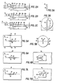
- Figs. lA through 1F illustrate vortex generating devices (such as generator plates 10a through 10f) according to various embodiments of the invention.
- Figs. 2A through 2C in addition to illustrating a top view of further embodiments of the invention (comprising generator plates 10g, 10h, and 10i), also selectively illustrate an axis of elongation 12 associated with each generator plate 10 of the various embodiments disclosed herein.
- the axis of elongation 12, and hence each generator plate 10 is oriented parallel to the direction of fluid flow as indicated by arrow 14 (from left to right). It should be understood that, with the exception of Figs. 3A, 3B, and 5B, in each of the Figures the fluid flows in a direction from the left to the right.
- the generator plate 10 of the invention may be fabricated from any suitable material or combinations of material, including plastic or metal. While the generator plate 10 may be mounted in a free standing aerodynamic configuration, it should also be understood that each embodiment of the invention may also be incorporated into a bounded fluid stream, such as a pipe or the like.
- each generator plate has a leading edge 16 and a trailing edge 18.
- the leading edge 16 of plate 10 When projected onto the axis of elongation 12, the leading edge 16 of plate 10 is separated from the trailing edge 18 by a length dimension L.
- each generator plate 10 also has a width W which is essentially perpendicular to the axis of elongation 12.
- the generator plate 10 is a narrow, elongated member such that the ratio L:W is preferably in the range of 15:1 to 100:1.
- a L:W ratio in this range gives the generator device a streamlined shape which reduces the turbulence of the resultant wake and the pressure drop associated therewith.
- Each generator plate 10 has two side surfaces 20 which extend from the leading edge 16 to the trailing edge 18. Although the side surfaces 20 are predominantly parallel to the axis of elongation 12 as viewed in Figs. 2A through 2C, the side surfaces 20 include leading portions 22 and trailing portions 24 (defined with respect to the direction of flow as indicated by arrow 14) which are not necessarily parallel to the axis 12. In.this respect, Figs. 2A, 2 B , and 2C each show separate embodiments having different configurations for the leading portions 22 of the side surfaces 20.
- leading portions 22g of side surfaces 20g are essentially straight lines as viewed from above and intersect the axis of elongation 12 at an angle alpha ⁇ preferably in the range from 5° to 30°, thereby forming the leading edge 16g.
- leading portions 22h of the side surfaces 20h gradually taper inwardly to form the leading edge 16g.
- leading portion 22i remains substantially parallel to the axis of elongation 12 while leading portion 22i' intersects leading portion 22i at an angle beta ⁇ which is preferably in the range from 5° to 30°.
- each generator plate 10 may have a leading edge 16 which is essentially straight with respect to the height dimension h or, as illustrated in Fig. lE, may have a leading edge 16e which is curved with respect to the height h.
- the generator plates 10 of the different embodiments of the invention have a shedding section comprising an aperture 26 which intersects the side surfaces 20 and extend into the plate 10 along the width dimension W.
- the aperture 26 may be a suitable indentation on the side surface 20 or the aperture 26 may extend completely through the plate 10.
- the aperture 26 may take on numerous geometrical shapes as hereinafter exemplified with reference to the embodiments of Fig. lA through 1D
- the aperture 26 of each embodiment has a leading aperture edge 28 and a trailing aperture edge 30 with respect to the direction of flow as indicated by arrow 14.
- the leading aperture edges 28 intersect the side surfaces 20 of the plate 10 to form shedding corners 32 which are preferably sharp as seen from above in Figs. 2A through 2C.
- the leading aperture edges 28 are preferably a continuous curve without any sharp discontinuities.
- the aperture 26 may take on several exemplary geometrical configurations as illustrated in Figs. lA through 1D.
- the embodiment of Fig. lA shows a circular aperture 26a; the embodiment of Fig. 1B shows a substantially eliptical aperture 26b having its major axis parallel to the axis of elongation 12; the embodiment of Fig. lC illustrates a substantially elliptical aperture 26c having a major axis perpendicular to the axis of elongation 12; and, the embodiment of Fig. 1B illustrates a substantially "D"-shaped aperture 26d with a relatively straight leading edge 28d smoothly tapered at its extremes for intersecting the substantially arcuate trailing aperture edge 30d.
- Figs. lA through 1D show a distance d which is the greatest distance from the leading aperture edge 28 to the trailing aperture edge 30. That is, distance d is the distance from the most upstream portion of edge 28 to the most downstream portion of edge 30.
- a ratio d:W is preferably in the range of 5:1 to 30:1.
- a ratio c:W is preferably in the range of 2:1 to 9:1.
- leading portions 22 have a length a (as projected on the axis of elongation 12) such that the ratio of the length a to the width W (a:W) should preferably be less than 5:1 and more preferably less than 3:1 to minimize variations caused by kinematic viscosity effects (such as changing pressure, temperature, and humidity in the fluid).
- any of the embodiments of the invention described herein may be utilized as a free standing aerodynamical configuration (as illustrated in Fig. 3A) or may be incorporated into a flow channel (such as a pipe 34 as seen in the front cross-sectional view of Fig. 3B).
- a flow channel such as a pipe 34 as seen in the front cross-sectional view of Fig. 3B.
- the generator plate 10 of Fig. 3B has a channel blockage area equal to the product of its height h times the width W.
- the generator plate 10 of the various embodiments of the invention may operate while blocking less than 1/5 of the cross-sectional area of the channel 34, and may preferably operate while blocking less than 1/15 of the channel 34. Yet, the generator plate 10 of the various embodiments of the invention produces reliably stable vortices through a wide range of flow velocities.
- a trailing portion 24 of the side surfaces 20 tapers inwardly to the trailing edge 18 of the plate 10.
- the taper may be very gradual as shown with respect to trailing portions 24h of Fig. 2B; or, the trailing portions may be sharp as illustrated by trailing portions 24g of Fig. 2A.
- Figs. 4A and 4B illustrate an additional embodiment of the invention wherein a generator plate 10j has side surfaces 20j spanning a leading edge 16j and a trailing edge 18j.
- a generator member 36 preferably a wire, is mounted on the leading edge 16j of generator plate 10j so as to extend upstream along the axis of elongation 12.
- the member 36 is preferably arcuate so as to be attached to leading edge 16j at two points.
- member 36 may assume various geometrical configurations, including that of a substantially linear segment.
- the arcuate member 36. and dimple 38 circumscribe an aperture 26j of which the generator member 36 is a leading aperture edge and the dimple 38 is a trailing aperture edge
- Figs. 4A and 4B are similar to the embodiments previously described.
- the dimensional ratios discussed above are applicable to the Fig. 4A and 4B embodiments when considering the length dimension L to extend from the furthermost upstream portion of the generator member 36 to-the trailing edge 18j.
- the leading edges 16j and the trailing edges 18j may be tapered in any of the above-described manners.
- Figs. 5A and 5B illustrate the generator plate 10 positioned in a flow channel 34 such that the axis of elongation 12 of generator plate 10 is parallel to the direction of the fluid flow as indicated by arrow 14.
- Fig. 5B illustrates flow channel 34 having a circular cross-section, it should be understood that the flow channel 34 may be any appropriate channel.
- Flow channel 34 of Figs. 5A and 5B has a first channel wall 40 and a second channel wall 42 which are both parallel to the direction of fluid flow and which face each other.
- Mounted in the first channel wall 40 is a transmitting transducer 44; mounted in the second channel wall 42 is a receiving transducer 46.
- the transducers 44, 46 are mounted on the opposing channel walls such that a signal travelling between the transducers 44, 46 would pass through the aperture 26 of the generator plate 10.
- the transmitting transducer 44 and the receiving transducer 46 are connected to suitable electrical circuitry for determining the relative velocity between the fluid stream and the generator plate 10.
- United States Patent 3,680,375 to Joy' et al. is incorporated herein by reference as an-example of the suitable electrical circuitry compatible with the embodiments of this invention.
- Fig. 6A and 6B illustrate a further embodiment of the invention wherein a sensor 48 is mounted on the trailing aperture edge 30 of the generator plate 10.
- the embodiments of Fig. 7A and 7B illustrate the mounting of a sensor 50'on a portion of the generator plate 10 between the trailing aperture edge 30 and the trailing edge 18 of the generator plate 10.
- Various sensor devices may be used for the sensors of the Fig. 6 and 7 embodiments.
- the sensors 48 and/or 50- may be hot-wire devices or capacitance devices.
- the generator plates 10 of the Fig. 6 and 7 embodiments are illustrated as positioned within a flow channel 34, it should again be understood that these embodiments may also be freestanding aerodynamical configurations.
- Fig. 1F comprises a generator plate 10f which may combine one or more of the features of the above-described embodiments.
- the Fig. 1F embodiment has surface discontinuities 52 on each side surface 20f. While the surface discontinuities 52 may take various forms, such as raised or elevated portions, the Fig. 1F illustration depicts the surface discontinuities as holes extending through the width W of plate 10f.
- each of the generator plates 10 is oriented so that its axis of elongation 12 is parallel to the direction of fluid flow as indicated by arrow 14.
- the ; essentially sharp leading edge 16 of the generator plate 10 configured according to either of the Fig. 2A, Fig. 2B, or 2C, embodiments prevents the formation of a sizeable stagnation area on the upstream surface of the plate 10. Hence, the pressure changes associated with the shifting of the stagnation region is' reduced and the effect thereof on the pressure gradients influencing. vortex detachment is minimized.
- vortices detach from the generator plate 10 at the shedding corners 32 which lie along the leading aperture edge 28 of the aperture 26.
- the preferably sharp corners 32 of the leading aperture edge 28 permit the formation of well-formed, stable vortices.
- the vortices detach from the leading aperture edge 28 along a shedding height which, when projected on a plane perpendicular to the side surfaces 20 of the plate 10, has a length c which is preferably less than the height b of the aperture 26.
- the transmitting transducer 44 directs a signal, such as a sonic signal, towards vortices 54 in the vicinity of the aperture 26.
- the receiving transducer 46 receives a signal modulated by the vortices and uses the signal as an indication of the relative velocity of the fluid in the manner described in the Joy et al. 375 patent.
- the various embodiments of the invention may be utilized with numerous types of sensors in the manners hereinbefore described, including sensors for measurements of velocity and/or mass flow.
- the sensors mounted on the generator plate 10 may be sensors for determining parameters other than the rate of vortex generation.
- the narrow, elongate shape of the generator plate 10 generally provides a laminar flow in the region near the shedding corners 32.
- the portion of generator plate 10 extending from the trailing aperture edge 30 to the trailing edge 18 acts to separate the two sides of the vortex street thereby preventing interaction of the vortices following detachment. It is thought that the side surfaces 20 downstream from the trailing aperture edge 30 dissipate the vortices by viscous action, thus reducing the effect of the vortex street on the whole flow stream. This effect is believed to be responsible for the reduced pressure drop of the generator plate 10 as compared to prior art shedding objects.
- the trailing portions 24 of the surfaces 20 are tapered to reduce the magnitude of turbulent shedding from the rear of the generator plate 10. This has the practical effect of reducing the pressure drop and eliminating audible noises (such as whistles) which would normally be associated with a blunt termination.
- Fig. 4A and 4B embodiments closely resembles that described above except that the generator member 36 is the furthest upstream portion of the generator plate 10j. Accordingly, the narrow generator element 36 does not produce a sizable stagnation region and promptly sheds vortices, thereby forming a vortex street.
- sensors may be mounted in a variety of.configurations, including a variation of Fig. 4B wherein generator plate 10j may be mounted in a flow channel (in the manner of the embodiment of Fig. 5A and Fig. 5B) so that a signal may be transmitted through the vortex street in the vicinity of the aperture 26j.
- the sides surfaces 20 of the generator plate 10 are provided with at least one surface disruption or surface discontinuity 52.
- the surface disruption 52 may take various forms, such as a protuberance (that is, a raised or elevatetd portion) or a circular hole
- the Fig. 8 illustration depicts the surface disruption as a radiused slot in the side surface 20.
- the radiused slot is formed in side surface 20 so that its greater dimension is parallel to the direction of fluid flow.
- the radiused slot has a 0.5 inch height dimension and 1.5 inch length dimension relative to an aperture 26 of 1.0 inch diameter.
- a surface disruption such as a hole or slot may be an indentation in the side surface 20 or may, as illustrated in Fig. 9, extend entirely through the width of the plate 10. Further, the surface disruptions may preferably be arranged symmetrically with respect to the aperture 26.
- The'Fig. 10 device resembles the Figs. 4A and 4B structure.
- the generator plate 10j also has provided on its side surface 20j at least one surface disruption, or surface discontinuity 52.
- the surface disruption 52 may take several forms.
- Fig. 10 also depicts a surface disruption as a radiused slot.
- a boundary layer develops along side surfaces 20 of the generator plate 10 from the leading edge 16 to the trailing edge 18.
- the boundary layer would be either laminar, transitional, or turbulent.
- a wholly laminar or wholly turbulent boundary layer does not deletriously affect the vortex street created by the shedding corners 32 or the generator member 36.
- the aforedescribed frictional drag has a deleterious and unpredictable impact upon the fluid flow velocity.
- the surface discontinuities or surface disruptions 52 on the side surfaces 20 of the generator plate 10 generate boundary-layer turbulence which eliminates the formation of a boundary-layer transition region and permits the velocity profile of the flow to develop without further disturbances. With the provision of the surface discontinuities 52 the boundary layer does not shear off from the plate so as to effect the vortex shedding sections of the respective embodiments.
Landscapes
- Physics & Mathematics (AREA)
- Fluid Mechanics (AREA)
- General Physics & Mathematics (AREA)
- Measuring Volume Flow (AREA)
Priority Applications (1)
| Application Number | Priority Date | Filing Date | Title |
|---|---|---|---|
| AT80304741T ATE7334T1 (de) | 1979-12-28 | 1980-12-29 | Wirbelgenerator. |
Applications Claiming Priority (6)
| Application Number | Priority Date | Filing Date | Title |
|---|---|---|---|
| US06/108,196 US4312237A (en) | 1979-12-28 | 1979-12-28 | Vortex generating device |
| US108196 | 1979-12-28 | ||
| US06/108,066 US4312236A (en) | 1979-12-28 | 1979-12-28 | Vortex generating device |
| WOPCT/US80/01622 | 1980-12-05 | ||
| PCT/US1980/001622 WO1981001878A1 (en) | 1979-12-28 | 1980-12-05 | Vortex generating device |
| US108066 | 1998-06-30 |
Publications (2)
| Publication Number | Publication Date |
|---|---|
| EP0032059A1 true EP0032059A1 (de) | 1981-07-15 |
| EP0032059B1 EP0032059B1 (de) | 1984-05-02 |
Family
ID=27373609
Family Applications (1)
| Application Number | Title | Priority Date | Filing Date |
|---|---|---|---|
| EP80304741A Expired EP0032059B1 (de) | 1979-12-28 | 1980-12-29 | Wirbelgenerator |
Country Status (2)
| Country | Link |
|---|---|
| EP (1) | EP0032059B1 (de) |
| AU (1) | AU6705781A (de) |
Cited By (3)
| Publication number | Priority date | Publication date | Assignee | Title |
|---|---|---|---|---|
| EP0077810B1 (de) * | 1981-04-30 | 1985-07-03 | Ford-Werke Aktiengesellschaft | Vorrichtung zum erzeugen von wirbeln |
| EP0207321A1 (de) * | 1985-07-03 | 1987-01-07 | RMG electronic GmbH | Vorrichtung zur Durchflussmessung |
| EP0278531A3 (en) * | 1982-09-16 | 1988-10-26 | Ford Motor Company Limited | Vortex flow meter frequency adjustment |
Citations (1)
| Publication number | Priority date | Publication date | Assignee | Title |
|---|---|---|---|---|
| US2869366A (en) * | 1955-03-21 | 1959-01-20 | Northrop Aircraft Inc | Vortex frequency airspeed indicator |
Family Cites Families (3)
| Publication number | Priority date | Publication date | Assignee | Title |
|---|---|---|---|---|
| FR1228750A (fr) * | 1958-06-26 | 1960-09-02 | Procédé et dispositifs pour l'étude de l'écoulement d'un fluide le long d'une paroi | |
| US3564915A (en) * | 1967-09-27 | 1971-02-23 | Yokogawa Electric Works Ltd | Current meter or flow meter |
| JPS4978573A (de) * | 1972-11-30 | 1974-07-29 |
-
1980
- 1980-12-05 AU AU67057/81A patent/AU6705781A/en not_active Abandoned
- 1980-12-29 EP EP80304741A patent/EP0032059B1/de not_active Expired
Patent Citations (1)
| Publication number | Priority date | Publication date | Assignee | Title |
|---|---|---|---|---|
| US2869366A (en) * | 1955-03-21 | 1959-01-20 | Northrop Aircraft Inc | Vortex frequency airspeed indicator |
Cited By (3)
| Publication number | Priority date | Publication date | Assignee | Title |
|---|---|---|---|---|
| EP0077810B1 (de) * | 1981-04-30 | 1985-07-03 | Ford-Werke Aktiengesellschaft | Vorrichtung zum erzeugen von wirbeln |
| EP0278531A3 (en) * | 1982-09-16 | 1988-10-26 | Ford Motor Company Limited | Vortex flow meter frequency adjustment |
| EP0207321A1 (de) * | 1985-07-03 | 1987-01-07 | RMG electronic GmbH | Vorrichtung zur Durchflussmessung |
Also Published As
| Publication number | Publication date |
|---|---|
| EP0032059B1 (de) | 1984-05-02 |
| AU6705781A (en) | 1981-07-22 |
Similar Documents
| Publication | Publication Date | Title |
|---|---|---|
| Bearman | The effect of base bleed on the flow behind a two-dimensional model with a blunt trailing edge | |
| US4350047A (en) | Vortex-shedding flowmeter having two bluff bodies | |
| US3589185A (en) | Vortex type flowmeter | |
| US5150619A (en) | Vortex flowmeters | |
| US5808209A (en) | Vortex fluid meter including a profiled pipe | |
| US4297898A (en) | Stabilized vortex-shedding flowmeter | |
| US3948097A (en) | Flow velocity measuring device | |
| US4312236A (en) | Vortex generating device | |
| US4312237A (en) | Vortex generating device | |
| US4030355A (en) | Obstacle assembly for vortex type flowmeter | |
| US4173143A (en) | Fluid flow measuring apparatus | |
| EP0032059B1 (de) | Wirbelgenerator | |
| US4457181A (en) | Narrow profile vortex shedding body | |
| WO1981001878A1 (en) | Vortex generating device | |
| US4409851A (en) | Oscillating vane flowmeter | |
| US3927564A (en) | Vortex type flowmeter | |
| EP0581163B1 (de) | Wirbeldurchflussmesser | |
| US5569859A (en) | Vortex flow sensor with a drag body | |
| US4562745A (en) | Flowmeter | |
| US4418578A (en) | Low noise vortex shedding fluid flow sensor | |
| EP0077810B1 (de) | Vorrichtung zum erzeugen von wirbeln | |
| EP0309607B1 (de) | Als flüssiger Oszillator ausgebildeter Durchflusssensor mit Ablenkplatte | |
| KR100201077B1 (ko) | 평균 피토관형 유량측정장치 | |
| CA1182377A (en) | Vortex generating device | |
| GB2102953A (en) | Flow meters and resistance elements therefor |
Legal Events
| Date | Code | Title | Description |
|---|---|---|---|
| PUAI | Public reference made under article 153(3) epc to a published international application that has entered the european phase |
Free format text: ORIGINAL CODE: 0009012 |
|
| AK | Designated contracting states |
Designated state(s): AT BE CH DE FR GB IT LU NL SE |
|
| 17P | Request for examination filed |
Effective date: 19811002 |
|
| ITF | It: translation for a ep patent filed | ||
| GRAA | (expected) grant |
Free format text: ORIGINAL CODE: 0009210 |
|
| AK | Designated contracting states |
Designated state(s): AT BE CH DE FR GB IT LI LU NL SE |
|
| PG25 | Lapsed in a contracting state [announced via postgrant information from national office to epo] |
Ref country code: SE Effective date: 19840502 Ref country code: NL Effective date: 19840502 Ref country code: LI Effective date: 19840502 Ref country code: CH Effective date: 19840502 Ref country code: BE Effective date: 19840502 Ref country code: AT Effective date: 19840502 |
|
| REF | Corresponds to: |
Ref document number: 7334 Country of ref document: AT Date of ref document: 19840515 Kind code of ref document: T |
|
| REF | Corresponds to: |
Ref document number: 3067717 Country of ref document: DE Date of ref document: 19840607 |
|
| ET | Fr: translation filed | ||
| REG | Reference to a national code |
Ref country code: CH Ref legal event code: PL |
|
| NLV1 | Nl: lapsed or annulled due to failure to fulfill the requirements of art. 29p and 29m of the patents act | ||
| PG25 | Lapsed in a contracting state [announced via postgrant information from national office to epo] |
Ref country code: LU Free format text: LAPSE BECAUSE OF NON-PAYMENT OF DUE FEES Effective date: 19841231 |
|
| PLBE | No opposition filed within time limit |
Free format text: ORIGINAL CODE: 0009261 |
|
| STAA | Information on the status of an ep patent application or granted ep patent |
Free format text: STATUS: NO OPPOSITION FILED WITHIN TIME LIMIT |
|
| 26N | No opposition filed | ||
| PGFP | Annual fee paid to national office [announced via postgrant information from national office to epo] |
Ref country code: FR Payment date: 19891229 Year of fee payment: 10 |
|
| PGFP | Annual fee paid to national office [announced via postgrant information from national office to epo] |
Ref country code: GB Payment date: 19891231 Year of fee payment: 10 |
|
| PGFP | Annual fee paid to national office [announced via postgrant information from national office to epo] |
Ref country code: DE Payment date: 19900830 Year of fee payment: 10 |
|
| PG25 | Lapsed in a contracting state [announced via postgrant information from national office to epo] |
Ref country code: GB Effective date: 19901229 |
|
| GBPC | Gb: european patent ceased through non-payment of renewal fee | ||
| PG25 | Lapsed in a contracting state [announced via postgrant information from national office to epo] |
Ref country code: FR Effective date: 19910830 |
|
| PG25 | Lapsed in a contracting state [announced via postgrant information from national office to epo] |
Ref country code: DE Effective date: 19910903 |
|
| REG | Reference to a national code |
Ref country code: FR Ref legal event code: ST |