EP0032071B1 - Abnutzungsanzeigeeinrichtung für Scheibenbremsen - Google Patents
Abnutzungsanzeigeeinrichtung für Scheibenbremsen Download PDFInfo
- Publication number
- EP0032071B1 EP0032071B1 EP19800401714 EP80401714A EP0032071B1 EP 0032071 B1 EP0032071 B1 EP 0032071B1 EP 19800401714 EP19800401714 EP 19800401714 EP 80401714 A EP80401714 A EP 80401714A EP 0032071 B1 EP0032071 B1 EP 0032071B1
- Authority
- EP
- European Patent Office
- Prior art keywords
- supporting member
- wear indicator
- conducting
- housing
- pad
- Prior art date
- Legal status (The legal status is an assumption and is not a legal conclusion. Google has not performed a legal analysis and makes no representation as to the accuracy of the status listed.)
- Expired
Links
- 239000011810 insulating material Substances 0.000 claims description 7
- 230000011664 signaling Effects 0.000 claims description 7
- 239000011368 organic material Substances 0.000 claims description 6
- 239000004020 conductor Substances 0.000 claims description 5
- 230000005611 electricity Effects 0.000 claims 2
- 238000005266 casting Methods 0.000 claims 1
- 238000000465 moulding Methods 0.000 description 3
- 238000004026 adhesive bonding Methods 0.000 description 2
- 239000002184 metal Substances 0.000 description 2
- 230000006835 compression Effects 0.000 description 1
- 238000007906 compression Methods 0.000 description 1
- 238000003754 machining Methods 0.000 description 1
- 238000004519 manufacturing process Methods 0.000 description 1
- 239000000463 material Substances 0.000 description 1
- 210000000056 organ Anatomy 0.000 description 1
- 235000012431 wafers Nutrition 0.000 description 1
Images

Classifications
-
- F—MECHANICAL ENGINEERING; LIGHTING; HEATING; WEAPONS; BLASTING
- F16—ENGINEERING ELEMENTS AND UNITS; GENERAL MEASURES FOR PRODUCING AND MAINTAINING EFFECTIVE FUNCTIONING OF MACHINES OR INSTALLATIONS; THERMAL INSULATION IN GENERAL
- F16D—COUPLINGS FOR TRANSMITTING ROTATION; CLUTCHES; BRAKES
- F16D66/00—Arrangements for monitoring working conditions, e.g. wear, temperature
- F16D66/02—Apparatus for indicating wear
- F16D66/021—Apparatus for indicating wear using electrical detection or indication means
- F16D66/022—Apparatus for indicating wear using electrical detection or indication means indicating that a lining is worn to minimum allowable thickness
- F16D66/023—Apparatus for indicating wear using electrical detection or indication means indicating that a lining is worn to minimum allowable thickness directly sensing the position of braking members
- F16D66/024—Sensors mounted on braking members adapted to contact the brake disc or drum, e.g. wire loops severed on contact
Definitions
- the present invention relates to a wear indicator device for disc brake pads.
- Some disc brake devices include brake pads or friction linings which are fitted with wear indicators isolated from the vehicle mass, and which, when in contact with the grounded disc, cause the ignition of a indicator light on the vehicle dashboard.
- one proceeds to the machining of a hole in the friction lining, intended to receive an electrically conductive wire which is held by gluing.
- a hole is cut in the metal frame in order to allow the fitting of a wear indicator consisting of an insulating sleeve in which a conductive plug is arranged.
- Patent DE-A-1 680 104 also relates to brake pads comprising an insulating support member and a wear indicator which is embedded in the limit zone between the support member and the friction lining.
- the wear indicator constituted by an electrically conductive member connected to an electrical signaling circuit is mounted on the support member made of insulating material beyond the connection surface between the support and friction lining.
- the arrangement allows mounting in or an insulating support member of an electrically conductive member and this beyond the normal connection plane between the support member and the friction lining in order to cause the indicator light to come on. and warn the driver before the friction lining is completely worn out.
- the device according to the invention allows a simplification of the manufacture of the plates intended to receive a wear indicator and a reduction in the cost price.
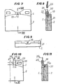
- FIGs 1 and 2 there is shown a disc brake pad which consists of a support member 1 in organic material on which is fixed, during a compression operation, a friction lining 2, as well as 'It is described in French patent No 7 722 752 of the applicant.
- a housing 3 in which is engaged an insulating plate 4 which is fixed to the support member 1, by means of 'a rivet 5 set in a hole in said support.
- a conductive wire 6 which is connected by a conductor 7 to an electrical signaling circuit comprising in particular an indicator light arranged on the dashboard of the vehicle.
- the conducting wire 6 being directed on the face of the pad located on the side of the friction lining 2, this results, when said friction lining is completely worn, contact with the brake disc and the closing of the supply circuit. of the signaling organ.
- FIGs 3 and 4 there is shown another embodiment of wear indicator which consists of a conductive pin 8 embedded in a sleeve or rivet 9, which is fixed in a hole 10 formed in the support member 1, said sleeve and the spindle 8 extending into a housing 11 formed in the friction lining 2.
- the pin 8 is connected to a conductive wire 12, which is coated in a plate 13 engaged in a housing 14 shaped in the rear face of the support member 1.
- FIGS. 5 and 6 another embodiment of a wear indicator is shown, consisting of an electrically conductive plug 15, force fitted into a housing 16 formed during molding in the support member 1.
- the embodiment of the housing 16 causes the molding to move the material constituting the support member beyond the normal plane 17 of connection between the support member and the friction lining, so that the conductive plug 15 s' extends beyond the normal plane 17 and that it is likely to come into contact with the brake disc during wear of the friction lining.
- the plug 15 has a pin 18 by which it can be connected by a conductive member to a signaling circuit.
- the plug 19 is arranged vertically in the upper middle part of the support member and extends beyond the normal plane 21 of connection between the support member and the friction lining.
- connection plug 23 which is capable of being engaged on a pin 24 of the plug 19, said connection plug being connected by a conductive member to a signaling circuit.
- Figures 10 and 11 show another embodiment of wear indicator which consists of a blade 25 of electrically conductive material and which is overmolded in a plate 26 of insulating material arranged and fixed in particular by gluing in a housing 27 formed in the support member 1 and the friction lining 2.
- the conductive strip 25 has a part 25a extending in a part of the housing 27 provided in the friction lining so as to establish contact with the brake disc at the end of the wear of the friction lining 2.
- the blade 25 At its end opposite to the part 25a the blade 25 has an uninsulated part 25b capable of being connected to a conductive wire.
Landscapes
- Engineering & Computer Science (AREA)
- General Engineering & Computer Science (AREA)
- Mechanical Engineering (AREA)
- Braking Arrangements (AREA)
Claims (6)
Applications Claiming Priority (2)
| Application Number | Priority Date | Filing Date | Title |
|---|---|---|---|
| FR7931999A FR2472697A1 (fr) | 1979-12-28 | 1979-12-28 | Dispositif de temoin d'usure pour plaquettes de freins a disques |
| FR7931999 | 1979-12-28 |
Publications (4)
| Publication Number | Publication Date |
|---|---|
| EP0032071A2 EP0032071A2 (de) | 1981-07-15 |
| EP0032071A3 EP0032071A3 (en) | 1981-12-02 |
| EP0032071B1 true EP0032071B1 (de) | 1984-05-30 |
| EP0032071B2 EP0032071B2 (de) | 1987-05-13 |
Family
ID=9233296
Family Applications (1)
| Application Number | Title | Priority Date | Filing Date |
|---|---|---|---|
| EP19800401714 Expired EP0032071B2 (de) | 1979-12-28 | 1980-12-01 | Abnutzungsanzeigeeinrichtung für Scheibenbremsen |
Country Status (3)
| Country | Link |
|---|---|
| EP (1) | EP0032071B2 (de) |
| DE (1) | DE3068070D1 (de) |
| FR (1) | FR2472697A1 (de) |
Families Citing this family (7)
| Publication number | Priority date | Publication date | Assignee | Title |
|---|---|---|---|---|
| FR2521241A1 (fr) * | 1982-02-10 | 1983-08-12 | Valeo | Plaquette de frein a disque auto-refroidie |
| GB2149034A (en) * | 1983-11-12 | 1985-06-05 | Hazel Grove Jig & Tool Co Limi | Brake pad wear indicator |
| FR2625374B1 (fr) * | 1987-12-24 | 1990-06-15 | Peugeot | Dispositif de connexion electrique |
| DE3820977C2 (de) * | 1988-06-22 | 1997-04-24 | Teves Gmbh Alfred | Verfahren zur Herstellung einer Warnanzeigevorrichtung für Belagverschleiß an Bremsbacken |
| DE4239179A1 (de) * | 1992-11-21 | 1994-05-26 | Teves Gmbh Alfred | Bremsbelag mit Verschleißwarnvorrichtung |
| DE10331734A1 (de) * | 2003-07-11 | 2005-02-03 | Bpw Bergische Achsen Kg | Bremspad-Verschleißanzeige |
| DE102011103696B3 (de) * | 2011-06-09 | 2012-12-06 | Knorr-Bremse Systeme für Nutzfahrzeuge GmbH | Bremsbelag einer Scheibenbremse |
Family Cites Families (3)
| Publication number | Priority date | Publication date | Assignee | Title |
|---|---|---|---|---|
| DE1680104A1 (de) * | 1968-02-19 | 1971-11-11 | Heidenreich Robert Dipl Ing | Funktions-UEberwachungs-Geraet fuer Kraftuebertragungs-Einrichtungen,insbesondere fuer Bremsanlagen und Kupplungen bei Kraftwagen |
| GB1394822A (en) * | 1971-05-21 | 1975-05-21 | Girling Ltd | Brake pad and a wear indicator therefor |
| FR2406128A1 (fr) * | 1977-07-25 | 1979-05-11 | Abex Pagid Equip | Procede de fabrication de garnitures pour freins a disques |
-
1979
- 1979-12-28 FR FR7931999A patent/FR2472697A1/fr active Granted
-
1980
- 1980-12-01 EP EP19800401714 patent/EP0032071B2/de not_active Expired
- 1980-12-01 DE DE8080401714T patent/DE3068070D1/de not_active Expired
Also Published As
| Publication number | Publication date |
|---|---|
| EP0032071A3 (en) | 1981-12-02 |
| FR2472697A1 (fr) | 1981-07-03 |
| EP0032071B2 (de) | 1987-05-13 |
| EP0032071A2 (de) | 1981-07-15 |
| DE3068070D1 (en) | 1984-07-05 |
| FR2472697B1 (de) | 1984-02-17 |
Similar Documents
| Publication | Publication Date | Title |
|---|---|---|
| EP0426715A1 (de) | Scheibenbremsbelag-abnutzungssensor. | |
| FR2481732A1 (fr) | Dispositif d'eclairage de serrure incorpore a une poignee de porte, notamment a une poignee de porte d'un vehicule automobile | |
| EP0032071A2 (de) | Abnutzungsanzeigeeinrichtung für Scheibenbremsen | |
| EP0006388B1 (de) | Abnutzungsanzeiger für Trommelbremse | |
| FR2740911A1 (fr) | Appareil electrique a bornes de raccordement protegees par un diaphragme a fixation par des ailes | |
| FR2552275A1 (fr) | Connecteur pour demarreur, notamment de vehicule automobile | |
| CA2238543A1 (en) | Brake actuator service limit sensor | |
| EP0050086B1 (de) | Bremslichtschalter für Motorfahrrad | |
| EP0204604A1 (de) | Druckplattenfeder für Scheibenbremse | |
| EP0026137B2 (de) | Abnutzungsanzeiger für Bremsbeläge | |
| EP0902602B1 (de) | Vorrichtung zum elektrischen Verbinden einer gedruckten widerstandsfähigen Leiterbahn mit dem Stromnetz | |
| FR2495252A1 (fr) | Frein a commande hydraulique muni d'un dispositif evitant l'elevation de temperature du liquide hydraulique | |
| EP0790165A1 (de) | Fahrzeug-Feststellbremse mit einem selbstreinigenden Massekontakt | |
| FR2465924A1 (fr) | Perfectionnement aux temoins d'usure pour plaquette de freins | |
| EP0035446B1 (de) | Reibelemente, insbesondere für Bremsschuhe, und Verfahren zu ihrer Herstellung | |
| EP0670613B1 (de) | Elektrisches Gerät, dessen Vorrichtung in einem wasserdichten Gehäuse montierbar ist, Versehen mit einer Abdeckung und einem Deckel | |
| EP0194938B1 (de) | Parklicht- und Fahrrichtungsblinkschalteinrichtung für Kraftfahrzeuge | |
| FR2937392A1 (fr) | Dispositif de freinage pour vehicule, comportant un cable electrique reliant un capteur d'usure a un connecteur electrique | |
| FR92357E (de) | ||
| EP0054480A1 (de) | Scheibenbremsbelagabnutzungsanzeigeanlage | |
| FR2617257A1 (fr) | Temoin d'usure d'organe de friction pour frein de vehicule automobile et organe de friction equipe d'un tel temoin | |
| FR2696220A1 (fr) | Dispositif détecteur de l'usure de plaquette de freins, notamment pour véhicule automobile. | |
| FR2625374A1 (fr) | Dispositif de connexion electrique | |
| FR2611080A1 (fr) | Mecanisme d'interrupteur a balai conducteur forme d'un simple fil, et interrupteur comportant un tel mecanisme | |
| FR2479754A1 (fr) | Feu, notamment feu arriere, pour vehicules automobiles |
Legal Events
| Date | Code | Title | Description |
|---|---|---|---|
| PUAI | Public reference made under article 153(3) epc to a published international application that has entered the european phase |
Free format text: ORIGINAL CODE: 0009012 |
|
| AK | Designated contracting states |
Designated state(s): BE DE GB IT LU NL |
|
| PUAL | Search report despatched |
Free format text: ORIGINAL CODE: 0009013 |
|
| AK | Designated contracting states |
Designated state(s): BE DE GB IT LU NL |
|
| 17P | Request for examination filed |
Effective date: 19811219 |
|
| ITF | It: translation for a ep patent filed | ||
| GRAA | (expected) grant |
Free format text: ORIGINAL CODE: 0009210 |
|
| AK | Designated contracting states |
Designated state(s): BE DE GB IT LU NL |
|
| REF | Corresponds to: |
Ref document number: 3068070 Country of ref document: DE Date of ref document: 19840705 |
|
| BECN | Be: change of holder's name |
Effective date: 19840530 |
|
| PLBI | Opposition filed |
Free format text: ORIGINAL CODE: 0009260 |
|
| 26 | Opposition filed |
Opponent name: ALFRED TEVES GMBH Effective date: 19850104 |
|
| NLR1 | Nl: opposition has been filed with the epo |
Opponent name: ALFRED TEVES GMBH |
|
| RAP2 | Party data changed (patent owner data changed or rights of a patent transferred) |
Owner name: ABEX EQUIPEMENT S.A. |
|
| NLT2 | Nl: modifications (of names), taken from the european patent patent bulletin |
Owner name: ABEX EQUIPEMENT S.A. TE GIF-SUR-YVETTE, FRANKRIJK. |
|
| PUAH | Patent maintained in amended form |
Free format text: ORIGINAL CODE: 0009272 |
|
| STAA | Information on the status of an ep patent application or granted ep patent |
Free format text: STATUS: PATENT MAINTAINED AS AMENDED |
|
| 27A | Patent maintained in amended form |
Effective date: 19870513 |
|
| AK | Designated contracting states |
Kind code of ref document: B2 Designated state(s): BE DE GB IT LU NL |
|
| ITF | It: translation for a ep patent filed | ||
| NLR2 | Nl: decision of opposition | ||
| NLR3 | Nl: receipt of modified translations in the netherlands language after an opposition procedure | ||
| ITTA | It: last paid annual fee | ||
| EPTA | Lu: last paid annual fee | ||
| PGFP | Annual fee paid to national office [announced via postgrant information from national office to epo] |
Ref country code: GB Payment date: 19971125 Year of fee payment: 18 |
|
| PGFP | Annual fee paid to national office [announced via postgrant information from national office to epo] |
Ref country code: NL Payment date: 19971130 Year of fee payment: 18 |
|
| PGFP | Annual fee paid to national office [announced via postgrant information from national office to epo] |
Ref country code: DE Payment date: 19971222 Year of fee payment: 18 |
|
| PGFP | Annual fee paid to national office [announced via postgrant information from national office to epo] |
Ref country code: BE Payment date: 19980115 Year of fee payment: 18 |
|
| PGFP | Annual fee paid to national office [announced via postgrant information from national office to epo] |
Ref country code: LU Payment date: 19980203 Year of fee payment: 18 |
|
| PG25 | Lapsed in a contracting state [announced via postgrant information from national office to epo] |
Ref country code: LU Free format text: LAPSE BECAUSE OF NON-PAYMENT OF DUE FEES Effective date: 19981201 Ref country code: GB Free format text: LAPSE BECAUSE OF NON-PAYMENT OF DUE FEES Effective date: 19981201 |
|
| PG25 | Lapsed in a contracting state [announced via postgrant information from national office to epo] |
Ref country code: BE Free format text: LAPSE BECAUSE OF NON-PAYMENT OF DUE FEES Effective date: 19981231 |
|
| BERE | Be: lapsed |
Owner name: S.A. ABEX EQUIPEMENT Effective date: 19981231 |
|
| PG25 | Lapsed in a contracting state [announced via postgrant information from national office to epo] |
Ref country code: NL Free format text: LAPSE BECAUSE OF NON-PAYMENT OF DUE FEES Effective date: 19990701 |
|
| GBPC | Gb: european patent ceased through non-payment of renewal fee |
Effective date: 19981201 |
|
| NLV4 | Nl: lapsed or anulled due to non-payment of the annual fee |
Effective date: 19990701 |
|
| PG25 | Lapsed in a contracting state [announced via postgrant information from national office to epo] |
Ref country code: DE Free format text: LAPSE BECAUSE OF NON-PAYMENT OF DUE FEES Effective date: 19991001 |