EP0032139A2 - Beheizte Glasscheibe und Herstellungsanlage - Google Patents
Beheizte Glasscheibe und Herstellungsanlage Download PDFInfo
- Publication number
- EP0032139A2 EP0032139A2 EP81400014A EP81400014A EP0032139A2 EP 0032139 A2 EP0032139 A2 EP 0032139A2 EP 81400014 A EP81400014 A EP 81400014A EP 81400014 A EP81400014 A EP 81400014A EP 0032139 A2 EP0032139 A2 EP 0032139A2
- Authority
- EP
- European Patent Office
- Prior art keywords
- guidelines
- carriage
- glazing
- wires
- bridge
- Prior art date
- Legal status (The legal status is an assumption and is not a legal conclusion. Google has not performed a legal analysis and makes no representation as to the accuracy of the status listed.)
- Granted
Links
- 238000004519 manufacturing process Methods 0.000 title claims abstract description 11
- 238000010438 heat treatment Methods 0.000 claims abstract description 34
- 229920001169 thermoplastic Polymers 0.000 claims abstract description 15
- 239000004416 thermosoftening plastic Substances 0.000 claims abstract description 15
- 230000001105 regulatory effect Effects 0.000 claims description 2
- 239000011229 interlayer Substances 0.000 description 3
- 230000010355 oscillation Effects 0.000 description 3
- 230000003247 decreasing effect Effects 0.000 description 2
- 239000010410 layer Substances 0.000 description 2
- 238000010408 sweeping Methods 0.000 description 2
- WFKWXMTUELFFGS-UHFFFAOYSA-N tungsten Chemical compound [W] WFKWXMTUELFFGS-UHFFFAOYSA-N 0.000 description 2
- RYGMFSIKBFXOCR-UHFFFAOYSA-N Copper Chemical compound [Cu] RYGMFSIKBFXOCR-UHFFFAOYSA-N 0.000 description 1
- 229910000863 Ferronickel Inorganic materials 0.000 description 1
- 229910001111 Fine metal Inorganic materials 0.000 description 1
- 241001233242 Lontra Species 0.000 description 1
- 230000015572 biosynthetic process Effects 0.000 description 1
- 239000004020 conductor Substances 0.000 description 1
- 229910052802 copper Inorganic materials 0.000 description 1
- 239000010949 copper Substances 0.000 description 1
- 238000006073 displacement reaction Methods 0.000 description 1
- 239000011521 glass Substances 0.000 description 1
- 239000011440 grout Substances 0.000 description 1
- 230000017525 heat dissipation Effects 0.000 description 1
- 238000009434 installation Methods 0.000 description 1
- 238000000034 method Methods 0.000 description 1
- 238000012986 modification Methods 0.000 description 1
- 230000004048 modification Effects 0.000 description 1
- 230000003287 optical effect Effects 0.000 description 1
- 229920000515 polycarbonate Polymers 0.000 description 1
- 239000004417 polycarbonate Substances 0.000 description 1
- 229920000193 polymethacrylate Polymers 0.000 description 1
- 229910052721 tungsten Inorganic materials 0.000 description 1
- 239000010937 tungsten Substances 0.000 description 1
Images

Classifications
-
- B—PERFORMING OPERATIONS; TRANSPORTING
- B32—LAYERED PRODUCTS
- B32B—LAYERED PRODUCTS, i.e. PRODUCTS BUILT-UP OF STRATA OF FLAT OR NON-FLAT, e.g. CELLULAR OR HONEYCOMB, FORM
- B32B17/00—Layered products essentially comprising sheet glass, or glass, slag, or like fibres
- B32B17/06—Layered products essentially comprising sheet glass, or glass, slag, or like fibres comprising glass as the main or only constituent of a layer, next to another layer of a specific material
- B32B17/10—Layered products essentially comprising sheet glass, or glass, slag, or like fibres comprising glass as the main or only constituent of a layer, next to another layer of a specific material of synthetic resin
- B32B17/10005—Layered products essentially comprising sheet glass, or glass, slag, or like fibres comprising glass as the main or only constituent of a layer, next to another layer of a specific material of synthetic resin laminated safety glass or glazing
- B32B17/10165—Functional features of the laminated safety glass or glazing
- B32B17/10376—Laminated safety glass or glazing containing metal wires
-
- B—PERFORMING OPERATIONS; TRANSPORTING
- B32—LAYERED PRODUCTS
- B32B—LAYERED PRODUCTS, i.e. PRODUCTS BUILT-UP OF STRATA OF FLAT OR NON-FLAT, e.g. CELLULAR OR HONEYCOMB, FORM
- B32B17/00—Layered products essentially comprising sheet glass, or glass, slag, or like fibres
- B32B17/06—Layered products essentially comprising sheet glass, or glass, slag, or like fibres comprising glass as the main or only constituent of a layer, next to another layer of a specific material
- B32B17/10—Layered products essentially comprising sheet glass, or glass, slag, or like fibres comprising glass as the main or only constituent of a layer, next to another layer of a specific material of synthetic resin
- B32B17/10005—Layered products essentially comprising sheet glass, or glass, slag, or like fibres comprising glass as the main or only constituent of a layer, next to another layer of a specific material of synthetic resin laminated safety glass or glazing
- B32B17/10009—Layered products essentially comprising sheet glass, or glass, slag, or like fibres comprising glass as the main or only constituent of a layer, next to another layer of a specific material of synthetic resin laminated safety glass or glazing characterized by the number, the constitution or treatment of glass sheets
- B32B17/10036—Layered products essentially comprising sheet glass, or glass, slag, or like fibres comprising glass as the main or only constituent of a layer, next to another layer of a specific material of synthetic resin laminated safety glass or glazing characterized by the number, the constitution or treatment of glass sheets comprising two outer glass sheets
-
- B—PERFORMING OPERATIONS; TRANSPORTING
- B32—LAYERED PRODUCTS
- B32B—LAYERED PRODUCTS, i.e. PRODUCTS BUILT-UP OF STRATA OF FLAT OR NON-FLAT, e.g. CELLULAR OR HONEYCOMB, FORM
- B32B17/00—Layered products essentially comprising sheet glass, or glass, slag, or like fibres
- B32B17/06—Layered products essentially comprising sheet glass, or glass, slag, or like fibres comprising glass as the main or only constituent of a layer, next to another layer of a specific material
- B32B17/10—Layered products essentially comprising sheet glass, or glass, slag, or like fibres comprising glass as the main or only constituent of a layer, next to another layer of a specific material of synthetic resin
- B32B17/10005—Layered products essentially comprising sheet glass, or glass, slag, or like fibres comprising glass as the main or only constituent of a layer, next to another layer of a specific material of synthetic resin laminated safety glass or glazing
- B32B17/1055—Layered products essentially comprising sheet glass, or glass, slag, or like fibres comprising glass as the main or only constituent of a layer, next to another layer of a specific material of synthetic resin laminated safety glass or glazing characterized by the resin layer, i.e. interlayer
- B32B17/10761—Layered products essentially comprising sheet glass, or glass, slag, or like fibres comprising glass as the main or only constituent of a layer, next to another layer of a specific material of synthetic resin laminated safety glass or glazing characterized by the resin layer, i.e. interlayer containing vinyl acetal
-
- H—ELECTRICITY
- H05—ELECTRIC TECHNIQUES NOT OTHERWISE PROVIDED FOR
- H05B—ELECTRIC HEATING; ELECTRIC LIGHT SOURCES NOT OTHERWISE PROVIDED FOR; CIRCUIT ARRANGEMENTS FOR ELECTRIC LIGHT SOURCES, IN GENERAL
- H05B3/00—Ohmic-resistance heating
- H05B3/84—Heating arrangements specially adapted for transparent or reflecting areas, e.g. for demisting or de-icing windows, mirrors or vehicle windshields
-
- H—ELECTRICITY
- H05—ELECTRIC TECHNIQUES NOT OTHERWISE PROVIDED FOR
- H05B—ELECTRIC HEATING; ELECTRIC LIGHT SOURCES NOT OTHERWISE PROVIDED FOR; CIRCUIT ARRANGEMENTS FOR ELECTRIC LIGHT SOURCES, IN GENERAL
- H05B2203/00—Aspects relating to Ohmic resistive heating covered by group H05B3/00
- H05B2203/016—Heaters using particular connecting means
-
- H—ELECTRICITY
- H05—ELECTRIC TECHNIQUES NOT OTHERWISE PROVIDED FOR
- H05B—ELECTRIC HEATING; ELECTRIC LIGHT SOURCES NOT OTHERWISE PROVIDED FOR; CIRCUIT ARRANGEMENTS FOR ELECTRIC LIGHT SOURCES, IN GENERAL
- H05B2203/00—Aspects relating to Ohmic resistive heating covered by group H05B3/00
- H05B2203/031—Heaters specially adapted for heating the windscreen wiper area
-
- Y—GENERAL TAGGING OF NEW TECHNOLOGICAL DEVELOPMENTS; GENERAL TAGGING OF CROSS-SECTIONAL TECHNOLOGIES SPANNING OVER SEVERAL SECTIONS OF THE IPC; TECHNICAL SUBJECTS COVERED BY FORMER USPC CROSS-REFERENCE ART COLLECTIONS [XRACs] AND DIGESTS
- Y10—TECHNICAL SUBJECTS COVERED BY FORMER USPC
- Y10T—TECHNICAL SUBJECTS COVERED BY FORMER US CLASSIFICATION
- Y10T29/00—Metal working
- Y10T29/49—Method of mechanical manufacture
- Y10T29/49002—Electrical device making
- Y10T29/49082—Resistor making
- Y10T29/49083—Heater type
Definitions
- the present invention relates to a monolithic or laminated heating glazing comprising a heating network of fine wires of electrical resistance embedded in a thermoplastic layer.
- the invention also relates to a device for manufacturing this new heated glazing.
- heated glazing of the type described above to equip vehicles for air, sea or land transport.
- These glazings are used in particular for windshields in aircraft, boats, cars and trains, for example. They comprise a network formed of fine metallic wires placed in parallel between two collecting strips (or collectors) connected to a source of electrical voltage external to the glazing.
- collectors collecting strips
- These conductors stretched in a straight line or folded into segments with rectilinear guidelines are most often wavy or crimped along these rectilinear guidelines so as to better distribute the heat dissipation, to reduce the importance of the phenomena of optical diffraction caused by the presence of the network, such as increasing the distance wire distance between collectors given.
- the electrical voltage, the diameter of the wire, its length and the spacing between wires are determined to obtain a specific power, expressed in watts per square decimetres, of approximately 2 W / dm 2 to 70 W / dm 2 depending on the use glazing.
- a specific power expressed in watts per square decimetres, of approximately 2 W / dm 2 to 70 W / dm 2 depending on the use glazing.
- the specific power generally varies between 3 and 10 W / dm2.
- these glazings heaters In maritime transport, these glazings heaters generally have a specific power of 10 to 20 W / dm 2 approximately whereas in aviation this specific power can vary from 15 to 70 W / dm 2 approximately.
- the entire windshield can be heated to prevent the formation of frost and fogging; the heating therefore guarantees in particular the correct operation of the wipers.
- the resistance wires are arranged, as already indicated, along generally parallel rectilinear guidelines; only the collars can be curved if necessary.
- their width leads to placing them on the edges of the glazing so as not to hinder vision.
- the wipers have rotational or circular translation movements.
- the invention overcomes the aforementioned drawbacks and proposes to create a heating network with optimal heating performance, formed of fine wires of electrical resistance embedded in a thermoplastic layer according to curved guidelines and preferably in an arc of a circle.
- the glazing according to the invention can be manufactured using fine metal wires commonly used in the manufacture of this type of glazing.
- the spacings between the guidelines of the wires will range from approximately 0.5 to 3 mm depending on the use of the glazing, the various parameters being chosen as in the current technique as a function of the specific power to be achieved.
- the heating network with electric wires having guidelines in an arc of a circle covers an area equal to or very close to the surface of the glazing swept by a wiper.
- the latter constitutes a circular band, for example a sector of a circular crown delimited by two rays or else a surface with at least two curved sides of very variable shape, this in relation to the type of wiper and its operation.
- the wires are preferably arranged along the guidelines of an arc of the same radius offset gradually.
- all the guidelines of the wires forming the network therefore belong to circular arcs of the same radius obtained by translation.
- the directors of the wires forming the apparent network hold to arcs of a circle of the same center but of different radii.
- the heating network When the heating network is formed of wires arranged in guidelines in circular arcs directly along them, it can cover a surface of very varied shape.
- the network can cover a surface in the form of a circular sector with an angle at any center and with wire directors with a small radius of arc of a circle.
- the network can have a surface of very varied shape when it is formed of crimped or wavy wires around the curved guidelines.
- the directors of the wires have a small radius of an arc of a circle and when they are very close to one another, the amplitude of the undulations must be sufficiently low in order to avoid heating disturbances. It is the same when the angle at the center of the sector covered by the network is too large.
- the invention also provides a device for the manufacture of a heating network formed of fine wires arranged in guidelines in an arc.
- the device according to the invention can comprise certain members of known devices most used for the production of heated glazing with a network formed of fine wires deposited along the rectilinear guidelines.
- This device comprises a horizontal plate supporting the thermoplastic sheet on which the electrical network must be embedded, plate associated with a bridge disposed above it , perpendicular to one of its axes on which slides in a back and forth movement a carriage carrying laying members.
- a heating head terminated by a thread guide for embedding the thread on the thermoplastic sheet, and by a crowbar resiliently biased towards the plate to apply against the surface of the sheet. ; secured to the heater head, this presser foot holds that - one at a constant distance from this surface.
- the laying members pivot at 180 ° C at the same time as a step-by-step advance mechanism of the plate shifts the latter from the carriage by the distance separating two consecutive wires, in the direction of the axis of the network which is none other than the axis of the above-mentioned plateau.
- the laying members are also animated by a rapid oscillation, of small amplitude, perpendicular to the back and forth of the carriage, by means of an eccentric driven by a rack disposed along the bridge.
- the device according to the invention further comprises means allowing the laying of the wire along curved guidelines, in particular in an arc of a circle and a step-by-step advance mechanism shifting the carriage and the plate relative to one otter .
- the device comprises not a rectilinear bridge but a curved bridge following an arc of a circle in a plane parallel to the surface of the plate.
- This device makes it possible to manufacture a glazing with a heating network formed of wires, the guidelines of which all have the form of a single arc of circle which can be an arc of a circle described by the wiper fitted to the glazing.
- this embodiment is not entirely satisfactory in several respects, by its cost, its lack of flexibility of use, the excessive deformation of the undulations of the network on the edges.
- the device comprises a rectilinear bridge as in the known art, but instead of being fixed, it is freely mounted at each of its ends on rails which are parallel to one another, oriented parallel to the aforementioned axis of the plateau ,; the carriage carrying the laying components and grout sant on the bridge is fixed by 1-lintermediary of a rod to a vertical axis located in the median plane of the plate supporting the thermoplastic sheet.
- the carriage During its back and forth movement along the bridge, the carriage, thus guided in translation by the bridge, then describes a trajectory in an arc of a circle of radius equal to the length of the connecting rod connecting it to the fixed point.
- This device allows the realization of a network of wires whose guidelines are arcs of a circle.
- the device comprises a mechanism for advancing the plate step by step and in addition a mechanism capable of adjusting the length of the connecting rod at each back and forth of the carriage.
- FIG. 1 represents a laminated glazing 1 fitted with a windscreen wiper 2 sweeping in rotation about an axis 0 a surface 3 shown in phantom. It is a laminated glazing comprising a film the interlayer on which is embedded a rectangular heating network 4 of fine wires of electrical resistance arranged along rectilinear guidelines 5 between two collecting strips 6a and 6b. Due to the scale, the undulations of the wires are not shown.
- the heating network covers a circonstrite zone on the surface 3. It therefore covers a large surface, part of which will be heated in vain in the event of rain and it will absorb a high electrical power.
- This glazing shows a laminated glazing 7 whose wiper rotates a surface 8.
- This glazing also includes a heating network 9 of fine wires arranged in rectilinear guidelines 10 between two collecting strips 11a and 11b.
- the heating network covers a restricted area, easier to heat but only intercepts part 12 of the surface 8.
- the zones heated in vain are reduced but the hatched parts 13a, 13b and 14 will remain frosted despite the operation heating; it follows that the wiper operates incorrectly.
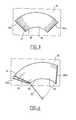
- FIG. 3 represents a glazing 15, provided with a windscreen wiper which sweeps in rotation a surface 16 and which, according to the invention comprises a sheet on which is embedded a heating network 17 of fine wires of electrical resistance arranged according to guidelines in a concentric circular arc and of variable radii between two collecting strips 19a and 19b.
- wires shown along the guidelines in the figure can advantageously be crimped or wavy around it for the reasons already mentioned above.
- the heating network completely and almost exactly covers the surface 16 swept by the wiper.
- the operation of the heating network is optimal because it heats the entire useful surface and only it, therefore at the cost of a minimum of electrical power.
- FIG. 4 represents a glazing 20 provided with a wiper, the blade 21 of which is slightly inclined relative to the handle 22.
- This wiper sweeps a surface 23 different from a circular crown sector.
- this glazing comprises a sheet on which is embedded a heating network 24 of fine wires of electrical resistance arranged along guidelines 25 in concentric arcs of circle and of variable radius between two strips of manifolds 26a and 26b.
- the heating network completely and exactly covers the surface 23 swept by the wiper.
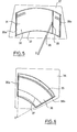
- FIG. 5 represents a glazing 27 provided with a windscreen wiper 28, the blade 29 of which moves in a circular translational movement covering a surface 30.
- the wires of the heating network 31 according to the invention are laid here according to guidelines 32 of constant radius between the collecting strips 33a and 33b, in successive strands offset by a constant quantity.
- FIG. 6 represents a laminated glazing 34 provided with a windscreen wiper which sweeps a surface 35, glazing which, according to the invention, includes an interlayer sheet on which is embedded a heating network 36 of fine corrugated wires of electrical resistance arranged according to guidelines 37 in circular arcs of the same radius, between two collector strips 38a and 38b.
- the heating network completely covers the area swept by the wiper.
- the maximum and minimum radii described by the wiper are approximately 30 and 60 centimeters respectively around a point 0. Its scanning angle and that formed by the two collector strips are approximately 70 degrees, but the radius of the arcs of the guiding circles are approximately 70 centimeters and the opening angle of their laying arcs is thus reduced to 60 degrees in their widest part.
- the wire guidelines are equidistant from 1 mm.
- the amplitude of the undulations is such that the length of wire for 1 meter of director is 1.20 m. It is also said that the ripple factor is 1.2.
- the wire is a tungsten wire of 15rm in diameter, about 400 ⁇ of resistance per linear meter.
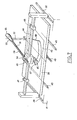
- Figure 7 schematically shows a device for manufacturing heated glazing and more precisely their heating networks.
- This device comprises a plate 39 mounted on slides 40 integral with a frame 41, plate which supports the thermoplastic sheet 42 generally made of pdlyvinylbutyral, and which, provided with drive means, is animated by means of a lead screw 43, with an adjustable stepwise advance movement.
- a rectilinear and horizontal bridge 44 supports a sliding carriage 45, itself carrying the members 46 for laying the wire on the thermoplastic sheet.
- the wire laying members are mounted elastically on a vertical axis and provided with an eccentric system driven by a rack disposed along the bridge (not shown) their im posing, perpenpendicular to the movement back and forth of the carriage, an oscillation movement of steps and amplitude low and adjustable, so that the wire is deposited substantially in the form of a sinusoid.
- Each stroke of the carriage is regulated by two lateral stops 47 and 48 mounted sliding on the bridge and causing the turning of the laying members.
- the bridge is freely mounted on two slides integral with the frame, arranged on either side of the plate in its direction of advance.
- the sliding carriage is also connected by a connecting rod 51 to a vertical axis 52 disposed in the median plane of the plate and integral with the frame 41.
- the connecting rod is formed by a threaded axis 53 mounted screwing on the pivot 54 and controlled in rotation in its bearing 55 secured to the axis 52 by a stepping motor 56 which thus makes it possible to modify the useful length of the connecting rod by an action similar to that of the lead screw on the plate.
- the carriage 45 carrying the laying members is placed above one end of a collecting strip, then, these members being put in place, it is made to slide in a back and forth movement along the bridge 44, at the same time that the connecting rod 51 causes the displacement of the latter on its slides 49 and 50 and that the rack animates the installation members with a transverse movement.
- the carriage follows a trajectory in an arc of a center circle corresponding to point 0, of radius equal to that of the connecting rod and delimited by the stops, the position of which will be modified as and when successive passages are made.
- the wire is thus deposited according to a curve of sinusoidal shape, of constant transverse pitch.
- the laying members rotate 180 ° at each end of travel; the movement is reversed and the next strand is placed along a director of the same radius, offset by the desired spacing according to an arc whose length can be adjusted at will.
- thermoplastic sheet carrying the heating network can be an interlayer sheet of laminated glazing.
- its assembly with the other elements of the laminate, for example with the glass sheets is carried out in a manner well known per se.
- thermoplastic sheet carrying the heating network may also be a rigid sheet of polycarbonate or polymethacrylate for example, the laying of the network of wires being carried out in the same way. In this case, it can itself constitute the heated glazing.
- the lead screw 43 remains stationary at the end of the successive strokes, so that the plate, therefore the center 0 of the arcs of the circle is kept fixed throughout laying operation.
- the motor 56 which advances by one step, thus reducing the useful radius of the connecting rod by a distance corresponding to the spacing of the successive strands. It therefore follows that as and when successive back and forth of the carriage, the wire is laid along arcs of circle of decreasing radius.
Landscapes
- Surface Heating Bodies (AREA)
- Joining Of Glass To Other Materials (AREA)
- Laminated Bodies (AREA)
Applications Claiming Priority (2)
| Application Number | Priority Date | Filing Date | Title |
|---|---|---|---|
| FR8000278A FR2473243A1 (fr) | 1980-01-08 | 1980-01-08 | Vitrage chauffant et dispositif de fabrication |
| FR8000278 | 1980-01-08 |
Publications (3)
| Publication Number | Publication Date |
|---|---|
| EP0032139A2 true EP0032139A2 (de) | 1981-07-15 |
| EP0032139A3 EP0032139A3 (en) | 1981-07-29 |
| EP0032139B1 EP0032139B1 (de) | 1985-04-24 |
Family
ID=9237308
Family Applications (1)
| Application Number | Title | Priority Date | Filing Date |
|---|---|---|---|
| EP81400014A Expired EP0032139B1 (de) | 1980-01-08 | 1981-01-08 | Beheizte Glasscheibe und Herstellungsanlage |
Country Status (8)
| Country | Link |
|---|---|
| US (2) | US4395622A (de) |
| EP (1) | EP0032139B1 (de) |
| JP (2) | JPS56109846A (de) |
| BR (1) | BR8100068A (de) |
| CA (1) | CA1173881A (de) |
| DE (1) | DE3170078D1 (de) |
| ES (1) | ES8200200A1 (de) |
| FR (1) | FR2473243A1 (de) |
Cited By (3)
| Publication number | Priority date | Publication date | Assignee | Title |
|---|---|---|---|---|
| EP0788294A2 (de) | 1996-01-30 | 1997-08-06 | Pilkington United Kingdom Limited | Elektrisch beheizbare Glasscheibe |
| EP0788295A2 (de) | 1996-01-30 | 1997-08-06 | Pilkington United Kingdom Limited | Elektrisch beheizbare Glasscheibe |
| EP0773705A3 (de) * | 1995-11-07 | 1997-11-19 | Saint-Gobain Vitrage | Verfahren und Vorrichtung zum Aufbringen und Befestigen eines dünnen Metaldrahtes auf der thermoplastischen Film einer Verbundglasscheibe |
Families Citing this family (18)
| Publication number | Priority date | Publication date | Assignee | Title |
|---|---|---|---|---|
| US4552611A (en) * | 1983-08-26 | 1985-11-12 | Astrolab Inc. | Conductor applying apparatus for rear window defrosters |
| US4970376A (en) * | 1987-12-22 | 1990-11-13 | Gte Products Corporation | Glass transparent heater |
| US5188687A (en) * | 1991-03-06 | 1993-02-23 | Labelmatic, Inc. | Label pickup and applicator assembly and method |
| US5653903A (en) * | 1995-06-27 | 1997-08-05 | Ppg Industries, Inc. | L-shaped heating element with radiused end for a windshield |
| US5708251A (en) * | 1995-10-30 | 1998-01-13 | Compucraft Ltd. | Method for embedding resistance heating wire in an electrofusion saddle coupler |
| US5886321A (en) * | 1996-12-19 | 1999-03-23 | Ppg Industries, Inc. | Arrangement for heating the wiper rest area of a vehicle windshield |
| DE10126869A1 (de) * | 2001-06-01 | 2002-12-19 | Saint Gobain Sekurit D Gmbh | Elektrisch beheizbare Scheibe |
| US20050098277A1 (en) * | 2002-02-06 | 2005-05-12 | Alex Bredemus | Reduced visibility insect screen |
| US6763875B2 (en) * | 2002-02-06 | 2004-07-20 | Andersen Corporation | Reduced visibility insect screen |
| US20080223842A1 (en) * | 2002-02-11 | 2008-09-18 | The Trustees Of Dartmouth College | Systems And Methods For Windshield Deicing |
| KR20040096565A (ko) * | 2002-02-15 | 2004-11-16 | 이스라엘 하다스 | 양식 시스템 |
| US7200921B2 (en) * | 2005-02-04 | 2007-04-10 | Automotive Components Holdings, Llc | Method of manufacturing a heated windshield |
| US20070281049A1 (en) * | 2006-06-05 | 2007-12-06 | John Pereira | Wire mat and apparatus for making the same |
| DE102007028755A1 (de) * | 2007-06-22 | 2008-12-24 | Bayerische Motoren Werke Aktiengesellschaft | Kraftfahrzeug |
| EP2063685A1 (de) * | 2007-11-20 | 2009-05-27 | Pilkington Italia S.p.A. | Kunststoffverglasung |
| EP2071901B1 (de) * | 2007-12-11 | 2012-08-15 | Volvo Car Corporation | Fenster mit Widerstandserwärmungselement |
| CN103200718B (zh) * | 2013-04-15 | 2014-12-03 | 福耀玻璃工业集团股份有限公司 | 一种在夹层玻璃的中间层上布设弧形加热丝的装置及方法 |
| CN106587663B (zh) * | 2016-12-13 | 2023-06-13 | 贵州杰傲建材有限责任公司 | 夹胶玻璃隔离加热装置 |
Family Cites Families (21)
| Publication number | Priority date | Publication date | Assignee | Title |
|---|---|---|---|---|
| FR846195A (fr) * | 1937-11-20 | 1939-09-11 | Perfectionnements aux pare-brise et autres objets en verre | |
| FR1464585A (fr) * | 1964-04-23 | 1967-01-06 | Saint Gobain | Vitrage chauffant pour véhicule, procédé et appareillage pour sa fabrication |
| GB1145367A (en) * | 1964-11-09 | 1969-03-12 | Saint Gobain | Improvements in or relating to heatable windows, more especially for vehicles |
| US3813519A (en) * | 1964-11-09 | 1974-05-28 | Saint Gobain | Electrically heated glass window |
| US3392759A (en) * | 1965-09-16 | 1968-07-16 | Barr & Stroud Ltd | Electrically heated windows or the like |
| US3874330A (en) * | 1968-09-27 | 1975-04-01 | Saint Gobain | Apparatus for applying strips of resistive material |
| BE755868A (fr) * | 1969-09-10 | 1971-02-15 | Libbey Owens Ford Co | Procede pour produire des intercouches pour pare-brise a antenne |
| US3590371A (en) * | 1969-12-31 | 1971-06-29 | Ppg Industries Inc | A method utilizing the color change with temperature of a material for detecting discontinuities in a conductor member embedded within a windshield |
| JPS4724681Y1 (de) | 1970-12-18 | 1972-08-03 | ||
| US3832527A (en) * | 1970-12-18 | 1974-08-27 | Asahi Glass Co Ltd | Defogging glass plate |
| US3778898A (en) | 1971-07-26 | 1973-12-18 | Gen Electric | Method of making a laminated electrically heated window |
| US3752348A (en) * | 1971-08-30 | 1973-08-14 | Ford Motor Co | Motor vehicle electrically heated windshield and backlight system |
| IT986606B (it) * | 1972-07-21 | 1975-01-30 | Glaverbel | Procedimento per fabbricare un pannello riscaldante trasparente e pannello ottenuto |
| FR2218710B1 (de) * | 1973-02-16 | 1976-04-30 | Saint Gobain | |
| JPS5028964A (de) * | 1973-07-16 | 1975-03-24 | ||
| US3910809A (en) | 1974-02-19 | 1975-10-07 | Libbey Owens Ford Co | Apparatus for producing interlayers for antenna-type windshields |
| JPS50150712A (de) * | 1974-05-27 | 1975-12-03 | ||
| NL181508C (nl) * | 1974-06-14 | 1987-09-01 | Stamicarbon | Werkwijze voor de bereiding van een d-aminozuuramide en een l-aminozuur en werkwijze voor de bereiding van d-fenylglycine. |
| US3964959A (en) | 1974-09-06 | 1976-06-22 | Easy Heat-Wirekraft, Msp Industries Corporation | Heating structure fabricating machine and method |
| CH611478A5 (de) * | 1977-01-27 | 1979-05-31 | Therglas Flaechenheizung | |
| JPS54146821A (en) * | 1978-05-09 | 1979-11-16 | Yoshioka Yutaka | Defogger metal wire and production thereof |
-
1980
- 1980-01-08 FR FR8000278A patent/FR2473243A1/fr active Granted
-
1981
- 1981-01-07 US US06/223,107 patent/US4395622A/en not_active Expired - Lifetime
- 1981-01-07 BR BR8100068A patent/BR8100068A/pt not_active IP Right Cessation
- 1981-01-07 CA CA000368049A patent/CA1173881A/fr not_active Expired
- 1981-01-08 DE DE8181400014T patent/DE3170078D1/de not_active Expired
- 1981-01-08 ES ES498373A patent/ES8200200A1/es not_active Expired
- 1981-01-08 JP JP81281A patent/JPS56109846A/ja active Pending
- 1981-01-08 EP EP81400014A patent/EP0032139B1/de not_active Expired
-
1982
- 1982-09-17 US US06/419,504 patent/US4436575A/en not_active Expired - Lifetime
-
1990
- 1990-07-09 JP JP1990072356U patent/JPH0435401Y2/ja not_active Expired
Cited By (3)
| Publication number | Priority date | Publication date | Assignee | Title |
|---|---|---|---|---|
| EP0773705A3 (de) * | 1995-11-07 | 1997-11-19 | Saint-Gobain Vitrage | Verfahren und Vorrichtung zum Aufbringen und Befestigen eines dünnen Metaldrahtes auf der thermoplastischen Film einer Verbundglasscheibe |
| EP0788294A2 (de) | 1996-01-30 | 1997-08-06 | Pilkington United Kingdom Limited | Elektrisch beheizbare Glasscheibe |
| EP0788295A2 (de) | 1996-01-30 | 1997-08-06 | Pilkington United Kingdom Limited | Elektrisch beheizbare Glasscheibe |
Also Published As
| Publication number | Publication date |
|---|---|
| FR2473243B1 (de) | 1984-01-20 |
| US4395622A (en) | 1983-07-26 |
| ES498373A0 (es) | 1981-11-01 |
| US4436575A (en) | 1984-03-13 |
| JPH0322030U (de) | 1991-03-06 |
| JPH0435401Y2 (de) | 1992-08-21 |
| DE3170078D1 (en) | 1985-05-30 |
| JPS56109846A (en) | 1981-08-31 |
| EP0032139A3 (en) | 1981-07-29 |
| BR8100068A (pt) | 1981-07-21 |
| FR2473243A1 (fr) | 1981-07-10 |
| ES8200200A1 (es) | 1981-11-01 |
| EP0032139B1 (de) | 1985-04-24 |
| CA1173881A (fr) | 1984-09-04 |
Similar Documents
| Publication | Publication Date | Title |
|---|---|---|
| EP0032139B1 (de) | Beheizte Glasscheibe und Herstellungsanlage | |
| EP0274777B1 (de) | Mit gesteuerter Deformation profilierter Flügel und Anwendung bei Schlagflügelflugzeugen | |
| EP0074453B1 (de) | Verfahren und Maschine zur Herstellung von Schraubennahtröhren aus Karton, und Röhren auf diese Art hergestellt | |
| FR3027334A1 (fr) | Installation pour couvrir et decouvrir une surface a l'aide de lames orientables automotrices | |
| EP0773705B1 (de) | Verfahren und Vorrichtung zum Aufbringen und Befestigen eines dünnen Metaldrahtes auf der thermoplastischen Film einer Verbundglasscheibe | |
| EP0256930A1 (de) | Nebelscheinwerfer für Kraftfahrzeuge mit einer Transversalwendel | |
| FR2658460A1 (fr) | Dispositif d'essuie-glace, notamment pour pare-brise de vehicule. | |
| CA2616708A1 (fr) | Dispositif eolien | |
| FR2875196A1 (fr) | Essuie-glasse de type pantographique | |
| FR2827225A1 (fr) | Dispositif formant pare-soleil a double filtre polarisant d'un vehicule automobile | |
| WO2006030117A1 (fr) | Dispositif de marquage | |
| FR2757815A1 (fr) | Dispositif de reglage en continu de l'angle d'incidence d'une raclette d'un essuie-vitre d'un vehicule automobile | |
| EP1663741B1 (de) | Verformbare kurbel für scheibenwischermechanismus mit einem länglichen, vierseitigen loch | |
| FR2761643A1 (fr) | Siege a amortissement variable | |
| FR2661146A1 (fr) | Essuie-glace. | |
| FR2483064A1 (fr) | Capteur d'energie solaire cylindro-parabolique | |
| FR2545025A1 (fr) | Machine destinee au bordage des feuilles de verre ou de glace chantournees | |
| FR2939172A1 (fr) | Rotor eolien | |
| FR3062830A1 (fr) | Dispositif d'entrainement en rotation d'un bras d'essuie-glace, notamment pour un pare-brise panoramique | |
| FR2686848A1 (fr) | Essuie-glace a raclette orientable. | |
| FR2757467A1 (fr) | Systeme de commande du fonctionnement d'un mecanisme d'essuie-vitre d'un vehicule automobile | |
| EP0711689B1 (de) | Getriebemotor mit einem hohlen, mit einem Verschlussdeckel versehenen Gehäuse, insbesondere für Kraftfahrzeug-Scheibenmischeranlage | |
| FR2674480A1 (fr) | Deflecteur d'air a ailerons, notamment pour vehicule automobile. | |
| FR2827241A1 (fr) | Dispositif d'essuie-glace a balayage lineaire d'un pare-brise de vehicule automobile | |
| EP3221271B1 (de) | Vorrichtung zur handhabung der kante eines floatglasbandes mit rad mit geneigter achse und installation mit einer derartigen vorrichtung |
Legal Events
| Date | Code | Title | Description |
|---|---|---|---|
| PUAI | Public reference made under article 153(3) epc to a published international application that has entered the european phase |
Free format text: ORIGINAL CODE: 0009012 |
|
| PUAL | Search report despatched |
Free format text: ORIGINAL CODE: 0009013 |
|
| AK | Designated contracting states |
Designated state(s): BE DE GB IT LU NL SE |
|
| AK | Designated contracting states |
Designated state(s): BE DE GB IT LU NL SE |
|
| 17P | Request for examination filed |
Effective date: 19820107 |
|
| ITF | It: translation for a ep patent filed | ||
| GRAA | (expected) grant |
Free format text: ORIGINAL CODE: 0009210 |
|
| AK | Designated contracting states |
Designated state(s): BE DE GB IT LU NL SE |
|
| REF | Corresponds to: |
Ref document number: 3170078 Country of ref document: DE Date of ref document: 19850530 |
|
| PLBE | No opposition filed within time limit |
Free format text: ORIGINAL CODE: 0009261 |
|
| STAA | Information on the status of an ep patent application or granted ep patent |
Free format text: STATUS: NO OPPOSITION FILED WITHIN TIME LIMIT |
|
| 26N | No opposition filed | ||
| ITTA | It: last paid annual fee | ||
| EPTA | Lu: last paid annual fee | ||
| PGFP | Annual fee paid to national office [announced via postgrant information from national office to epo] |
Ref country code: SE Payment date: 19941230 Year of fee payment: 15 Ref country code: GB Payment date: 19941230 Year of fee payment: 15 |
|
| PGFP | Annual fee paid to national office [announced via postgrant information from national office to epo] |
Ref country code: LU Payment date: 19950101 Year of fee payment: 15 |
|
| PGFP | Annual fee paid to national office [announced via postgrant information from national office to epo] |
Ref country code: BE Payment date: 19950124 Year of fee payment: 15 |
|
| EAL | Se: european patent in force in sweden |
Ref document number: 81400014.7 |
|
| PGFP | Annual fee paid to national office [announced via postgrant information from national office to epo] |
Ref country code: NL Payment date: 19950131 Year of fee payment: 15 |
|
| PGFP | Annual fee paid to national office [announced via postgrant information from national office to epo] |
Ref country code: DE Payment date: 19950218 Year of fee payment: 15 |
|
| PG25 | Lapsed in a contracting state [announced via postgrant information from national office to epo] |
Ref country code: LU Free format text: LAPSE BECAUSE OF NON-PAYMENT OF DUE FEES Effective date: 19960108 Ref country code: GB Effective date: 19960108 |
|
| PG25 | Lapsed in a contracting state [announced via postgrant information from national office to epo] |
Ref country code: SE Effective date: 19960109 |
|
| PG25 | Lapsed in a contracting state [announced via postgrant information from national office to epo] |
Ref country code: BE Effective date: 19960131 |
|
| BERE | Be: lapsed |
Owner name: SAINT-GOBAIN VITRAGE Effective date: 19960131 |
|
| PG25 | Lapsed in a contracting state [announced via postgrant information from national office to epo] |
Ref country code: NL Effective date: 19960801 |
|
| GBPC | Gb: european patent ceased through non-payment of renewal fee |
Effective date: 19960108 |
|
| NLV4 | Nl: lapsed or anulled due to non-payment of the annual fee |
Effective date: 19960801 |
|
| PG25 | Lapsed in a contracting state [announced via postgrant information from national office to epo] |
Ref country code: DE Effective date: 19961001 |
|
| EUG | Se: european patent has lapsed |
Ref document number: 81400014.7 |