EP0032169A1 - Système de signalisation fonctionnant avec radiation électromagnétique - Google Patents
Système de signalisation fonctionnant avec radiation électromagnétique Download PDFInfo
- Publication number
- EP0032169A1 EP0032169A1 EP80106917A EP80106917A EP0032169A1 EP 0032169 A1 EP0032169 A1 EP 0032169A1 EP 80106917 A EP80106917 A EP 80106917A EP 80106917 A EP80106917 A EP 80106917A EP 0032169 A1 EP0032169 A1 EP 0032169A1
- Authority
- EP
- European Patent Office
- Prior art keywords
- radiation
- signaling
- signaling system
- optical
- evaluation unit
- Prior art date
- Legal status (The legal status is an assumption and is not a legal conclusion. Google has not performed a legal analysis and makes no representation as to the accuracy of the status listed.)
- Withdrawn
Links
Images


Classifications
-
- G—PHYSICS
- G08—SIGNALLING
- G08B—SIGNALLING SYSTEMS, e.g. PERSONAL CALLING SYSTEMS; ORDER TELEGRAPHS; ALARM SYSTEMS
- G08B17/00—Fire alarms; Alarms responsive to explosion
- G08B17/10—Actuation by presence of smoke or gases, e.g. automatic alarm devices for analysing flowing fluid materials by the use of optical means
- G08B17/103—Actuation by presence of smoke or gases, e.g. automatic alarm devices for analysing flowing fluid materials by the use of optical means using a light emitting and receiving device
- G08B17/107—Actuation by presence of smoke or gases, e.g. automatic alarm devices for analysing flowing fluid materials by the use of optical means using a light emitting and receiving device for detecting light-scattering due to smoke
-
- G—PHYSICS
- G08—SIGNALLING
- G08B—SIGNALLING SYSTEMS, e.g. PERSONAL CALLING SYSTEMS; ORDER TELEGRAPHS; ALARM SYSTEMS
- G08B17/00—Fire alarms; Alarms responsive to explosion
- G08B17/10—Actuation by presence of smoke or gases, e.g. automatic alarm devices for analysing flowing fluid materials by the use of optical means
- G08B17/11—Actuation by presence of smoke or gases, e.g. automatic alarm devices for analysing flowing fluid materials by the use of optical means using an ionisation chamber for detecting smoke or gas
- G08B17/113—Constructional details
Definitions
- the invention relates to a signaling system with at least one signaling unit and an evaluation unit, an electromagnetic radiation source and a radiation receiver being provided, the radiation change of which is evaluated when a condition to be reported occurs with a signal circuit for signaling.
- Such alarm systems are used to report the most varied of undesirable conditions, for example to report a fire, to report dangerous gases or vapors, to undesirable temperature increases in rooms or on monitored devices, to monitor pressure or to protect against burglary or theft, etc., or for signal generation and processing , e.g. by means of EDP, to initiate protective or countermeasures in the event of an undesirable condition.
- the reporting units used are equipped with sensors that react to the relevant condition to be detected and are designed, for example, as fire, smoke, gas, radiation, temperature, pressure or intrusion detectors.
- the voltage supply from an evaluation unit to the individual signaling units arranged away therefrom and the signal return from these signaling units to the signaling center is generally carried out by means of electrical lines, possibly also by wireless transmission.
- electrical lines possibly also by wireless transmission.
- electrical interference often occurs during line transmission, for example mains impulses or in the lines in -induced electric voltages that lead ignalübush to a faulty response of the monitoring units and a faulty S.
- the supply voltage fluctuates due to the voltage drop in the lines, so that complex stabilization devices are required.
- the components of the signaling units are also exposed to environmental influences, for example temperature-dependent, so that complex compensation measures must be taken.
- the invention is based on the object of avoiding the disadvantages of known signaling systems described and, in particular, of creating a signaling system without electrical connections between the evaluation unit and the signaling units, which operates in a sensitive and stable manner and reliably over a long period of time and which has an extended area of use.
- the invention is characterized in that the radiation source, radiation receiver and signal circuit are combined to form the evaluation unit, the signaling units and the evaluation unit are connected to one another by means of radiation-conducting elements, so that electromagnetic radiation is supplied to the radiation source via at least one radiation-conducting element of the signaling unit or units, and that the reporting unit ten are designed to return radiation of changed intensity to the radiation receiver in the evaluation unit via at least one radiation-guiding element when a condition to be reported occurs.
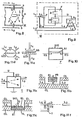
- a central evaluation unit E which has a radiation source Q and a radiation receiver R.
- the radiation source Q is fed by a signal circuit S, while the output signal of the radiation receiver R is fed back to the signal circuit S.
- the signal circuit S emits an alarm signal to an alarm unit A or causes, e.g. via EDP, the initiation of protective or countermeasures.
- Corresponding signal circuits are e.g. in large numbers from the technology of optical status detectors, e.g. Smoke detector, known.
- the radiation from the radiation source Q is emitted by a first radiation- terminating element L I , hereinafter referred to as light guide for brevity, as is customary in fiber optics, to a plurality of signaling units M 1 , M 2 ' M arranged away from the evaluation unit E. 3 ... distributed, which have sensors for the condition to be detected.
- the coupling and decoupling of the radiation for the individual signaling units takes place in the manner known in light guide technology with branching elements V 1 , V 2 ... Or W 1 , W 2 Connection to the individual signaling units via suitable known connections.
- the radiation is taken from the individual signaling units M 1 , M 2 , M 3 ... and returned to the receiver R in the evaluation unit E via a second light guide L 2 .
- the individual signaling units M 1 , M 2 , M 3 ... are therefore connected in parallel to the evaluation unit E in a group via the light guides L1 and L 2 .
- the entire group can be terminated behind the last signaling unit by an end element T, which is used to monitor the functioning of the light guides.
- the light guides used can either consist of a single fiber or of several, ie can be designed as a light guide bundle.
- Supply line L 1 and return line L 2 can also be combined into a single bundle.
- the type of light guide can be selected as required and in coordination with the signaling units of various types. For example, classic light guide from the multimode type can be used or, if expedient, from sogenan n - th single-mode type, such as described in: "Proceedings of the IEEE" 66 (1978), No. 7, p. 744 ff. Or: “Electronic Design” 23 (1979), p. 49 ff.
- any suitable lamp, a light or infrared-emitting diode or a LASER can be used as the radiation source Q, and the spectral distribution can be broadband, monochromatic, multimonochromatic or with a periodically variable wavelength.
- the spectrum To select this radiation source Q so that it is adapted to the transmission properties of the light guides, in particular when using single-mode light guides, and to the properties of the radiation receiver R. It may be expedient to operate the radiation source intermittently or in pulse form at a frequency of 1-10 12 Hz, for example 30 Hz, or to design the branching elements in a known manner so that the individual signaling units sequentially emit radiation in the manner of an optical one at different times Get multiplex.
- the radiation receiver R is expediently matched to the radiation source Q and can be designed, for example, as a photoconductor (Si, GaAs, PbSe, InSb), as a pyroelectric element (LiTaO 3 , TGS, PVF 2 ) or as a bolometer, or when the spectral composition of the radiation is used included a spectrometer.
- a photoconductor Si, GaAs, PbSe, InSb
- a pyroelectric element LiTaO 3 , TGS, PVF 2
- a bolometer or when the spectral composition of the radiation is used included a spectrometer.
- the individual sensors F, F 2 forming the signaling units are connected in series by the light guide system L 1 , L 2 , the individual sensors being connected by branches L 1 ", L2 to branching elements V 1 , W 1 , V 2 , W 2. If the individual sensors F 1 , F 2 and branches L 1 ", L 2 " have different spectral transmissions ⁇ 1 , ⁇ 2 , the location of the report can be identified in a simple manner.
- the system shown in Figure 3 works only with a single light guide L 1 , which is used both for radiation transmission and for signal return.
- This light guide L 1 is connected in series to branching elements V 0 , V 1 , which are designed, for example, as semi-transparent mirrors.
- the first element V o conducts both radiation further, as well as radiation returning to the receiver R via a branch; the second and the further elements V 1, V 2 ... directing radiation to a respective sensor is arranged in the branch F 1, F ..., as well as to the following ele- m ent and in the same way back.
- Each sensor F 1 , F 2 is terminated by an end member T 1 , T 2 ... and designed so that it sends the incoming radiation back in a changed form in the event of notification.
- the light guide L 1 is closed after the last branching element by an end member T 3 , which is used to monitor the function of the light guide.
- the signaling units M 1 , M 2 ... are designed such that they change their optical transmission properties when an environmental condition to be reported occurs. They consist of a suitable sensor and, if necessary, adapted additional elements. It is particularly expedient to design the signaling units in such a way that they do not return a signal in the normal state, so that many signaling units can be connected in parallel without their output signals interfering with one another.
- FIG. 4 shows a sensor F which is suitable for pressure, sound or vibration monitoring and is in the form of an acoustic-optical transducer and which can be operated using classic multimode light guides.
- a housing B is provided with an interior sealed by a membrane D, for example a Mylar film.
- the membrane D is reflective on the outside, for example aluminized, so that the radiation supplied via the light guide L 1 is reflected on the surface and can be absorbed by the light guide L 2 .
- the membrane D is deformed due to the action of sound vibrations, it changes the amount of radiation absorbed by the light guide L 2 , so that any action of sound vibrations or pressure pulses causes a change in the optical signal.
- FIG. 5 shows an acoustic-optical converter which is particularly suitable for operation with a single-mode light guide. It in turn has a housing B, which is closed off by an oscillatable membrane D, so that a certain reference pressure prevails inside.
- the evaluation unit must be adapted to the processing of positive or negative radiation pulses. It should be pointed out that instead of a single light guide, two light guides can also be provided, some of which are light guides. Exposed cores for a coupling section run parallel to one another, the pressure deforming the membrane and thus changing the optical coupling between the conductors.
- FIG. 6 shows an acoustic-piezoelectric transducer which contains a piezoelectric element P which is deformable under the action of sound and which emits an electrical charge or voltage in the event of any deformation.
- the piezoelectric element P has an element with electrically controllable transparency or reflection, for example a liquid crystal tall LC D , connected so that the permeability of this element is influenced by the voltage emitted by the piezoelectric element.
- the piezoelectric element can also be replaced by a pyroelectric element. Instead of sound, such a sensor reacts to changes in temperature. If an electrical bias on the liquid crystal LCD proves to be necessary, it can be generated on the solar cell 7 by means of the optical-electrical conversion shown in FIG.
- FIG. 7 shows a sensor element F of a signaling unit, in which the incoming light guide L and the outgoing light guide L 2 are connected in a loop.
- This loop consists of a radiation-conducting core C with a suitable known cover layer (cladding) 5.
- this cover layer is replaced by a state-sensitive layer 6, which changes its properties when exposed to gas, smoke, temperature or radiation, so that this Also change the transmission properties of the fiber loop. If an undesirable state of the ambient conditions occurs, for example dangerous gases occur, or the temperature rises above a dangerous value, the radiation transmitted in the light guide changes at the location of the state-sensitive layer 6, and a radiation change is determined in the evaluation unit that can be evaluated for alarm.
- the pressure or temperature sensitive light guide core can also by a thin film Waveguide intermediate piece made of a suitable elastomer, for example polydimethylsiloxane, between two light guides, which changes its transmission properties when exposed to pressure or temperature.
- FIG. 8 shows a smoke-sensitive alarm unit M which works on the scattered light principle and can serve, for example, as a fire alarm.
- a measuring chamber 1 is provided to which the air to be monitored has access.
- the measuring chamber 1 is closed on both sides by a cover 2 and 3, into which the light guide L 1 supplying the radiation and the light guide L 2 which removes the radiation are inserted centrally.
- the radiation end X of the first light guide L I is shielded from the receiving end Y of the second light guide L2 by a system of diaphragms 4, so that the light guide L 2 normally does not receive any radiation from the measuring chamber 1.
- the radiation-scattering particles such as smoke
- the radiated from the light guide L 1 radiation is at this Parti - scattered angles and the input Y of the optical waveguide L 2 is scattered radiation, which returned to the receiver R in the evaluation unit becomes.
- FIG. 9 shows a signaling unit M with a high-resistance sensor element F, which operates a voltage supply supply of a few volts, but only has a very low power consumption.
- the sensor element F can, for example, have an air-accessible toning chamber 8 in series connection with a less air-accessible or smoke-insensitive ionization chamber 9, which contain radioactive sources for ionizing the air.
- an ionization smoke detector the potential U at the junction of the two ionization chambers changes in accordance with the smoke density in the air-accessible ionization chamber 8.
- Solar cells for example a few silicon diodes, which come from a branch L 3 of the light guide, are used to supply power to the two series-connected ionization chambers 8 and 9 L received radiation. If the resistance of the sensor element F is large enough and the power consumption is correspondingly low, the voltage generated by these solar cells or silicon diodes 7 is sufficient to operate the sensor element F.
- the output potential U of the sensor element F controls a likewise very high-resistance electrical-optical converter T.
- This can consist, for example, of an element LCD with electrically controllable radiation transmission, for example a suitable liquid crystal, which is attached to a reflecting surface R 0 . Radiation is fed to this converter T via a branch L 4 of the light guide L 1 and removed again from the light guide L 2 . Normally, as long as the liquid crystal LCD is opaque to radiation, no signal is returned via this light guide L 2 .
- the output voltage U of the sensor element F and thus the control voltage of the converter T exceed a certain threshold, where will the flux sig crystal transparent, so that the radiation supplied via the light guide L 4 is reflected by the reflector R 0 and the evaluation unit receives radiation via the light guide L 2 .
- condition sensors can also be used, which react to other condition parameters to be detected, for example to certain gases or vapors, to changes in humidity, temperature or pressure, etc.
- a semiconductor element for example a MOSFET, a MOS capacitance or a Schottky diode with a gas, temperature, moisture smoke or pressure sensitive active layer AI.
- a semiconductor element for example a MOSFET, a MOS capacitance or a Schottky diode with a gas, temperature, moisture smoke or pressure sensitive active layer AI.
- POSFET a pressure and temperature sensitive MOSFET structure is known in which the active layer AI consists of polarized polyvinylidene fluoride.
- CFT Charge Flow
- the active layer consists of poly (p-aminophenylacetylene), whose characteristic changes as a function of moisture, and which is attached to a silicon dioxide layer.
- the hydrogen-sensitive MOSFET structure in which the active layer AI consists of palladium metal ("Vacuum” 27 (1976), p. 245).
- Sensors of the type described thus represent high-resistance controllable semiconductors in which the insulator layer AI is sensitive to gas, temperature, moisture, pressure and / or smoke has electrical properties according to the above examples.
- the bias voltage at the gate electrode EG is set approximately to the threshold value for the conductivity between the source electrode ES and the drain electrode ED. This conductivity changes when exposed to ambient conditions.
- the MOS capacitance properties can also be used.
- a signaling unit can be created in which both the transmission of the power required for operating the sensor elements and the signal transmission back to the evaluation unit are carried out in a purely optical way.
- the selection of the sensor elements is by no means limited to the components mentioned, but any high-resistance sensors for any state variables can be used, e.g. thin layers, semiconductors, in particular high-resistance transistors of the MOS type, or thin-film transistors (TFT), or piezoelectric elements that change their electrical properties under the influence of the ambient conditions or react to fire phenomena.
- FIG. 1a shows an electrical-optical converter with electrically controllable radiation deflection, for example of the LiNb0 3 type.
- a converter T has a chip EO, which has the property that when an electrical voltage U is applied, the light irradiated via an optical fiber L 4 is deflected in different directions depending on the voltage.
- the light guide L 2 which absorbs the radiation is now arranged at a point which has an output voltage of the sensor element F. and thus corresponds to an input voltage U of the converter at which an alarm message is to be issued.
- FIG. 11 b shows an electro-optical converter, in which the beam path in the air space between the two light guides Z 4 , L 2 through a piezo-electric element PB, for example through a multilayer polyvinyl difluoride (PVF 2 ) - Structure is changed, which is arranged in a gap between the light guides L 4 and L 2 covered with a cladding CL and is provided on both outer sides with electrodes EL.
- PB piezo-electric element
- PV 2 multilayer polyvinyl difluoride
- FIG. 11 c shows, as a further example, an electro-optical converter in which the beam path in the air space between the two light guides L 4 , L 2 is changed by an electrostatic semiconductor switch SI.
- a silicon oxide layer SIO is moved into the beam path by an applied voltage between the electrodes EL.
- This element also proved to be a very sensitive temperature sensor, since the two-layer system (electrode, SIO) acts like a very fine bimetal.
- a fire detector provided with such a transducer is therefore sensitive to both smoke and temperature.
- this electrical-optical converter can also be used to implement a branching element which acts as an optical multiplex.
- FIG. 11 d shows a branching element known as a "four-way liquid crystal switch" which, in the case of a signaling unit, analogous to that shown in FIG. 9, can simultaneously serve to branch off radiation for voltage generation and as an electrical-optical converter.
- the radiation supplied via the light guide L 1 enters a transparent body TR, then passes through a liquid crystal layer, and is removed from the light guide L 3 and supplied by this to the solar cells.
- the liquid crystal LCD receives a certain voltage U, the radiation is partially reflected on the surface of the layer and the reflected radiation is taken from the light guide L 2 and fed to the evaluation unit.
- the radiation picked up by the light guide L 3 drops somewhat, and consequently also the supply voltage of the sensor element, as a result of which the output voltage and the control voltage U of the liquid crystal are shifted further, so that the signaling unit becomes latched, ie the output signal on the light guide L 2 remains even after the alarm causes have ceased until the radiation supply to light guide L 1 is interrupted.
- FIG. 11 e shows a converter of the so-called "twisted nematic" type, which is also used for the radiation branching.
- a liquid crystal layer LCD is operated in transmission.
- the layer LCD is normally opaque, so that the radiation from the light guide L 1 is blocked. However, if the control voltage U reaches a predetermined value (approx. 1-1.5 V), the layer LCD becomes transparent and the radiation is absorbed by the other light guide L 2.
- a substrate SS is provided on the layer LCD, which has an opening at the location of the light guide, but carries solar cells 7 directly adjacent, which serve to supply the sensor element with voltage. Since the radiation emerges from the light guide L 1 in the form of a radiation cone, the solar cells 7 also receive sufficient radiation intensity to ensure the voltage supply.
- the "transphaser” also proves to be expedient, in which the permeability as a function of the incident light intensity shows a hysteresis.
- Fig. 11f Another purely optical branching element is indicated in Fig. 11f.
- the coupling of light from the conductor L 4 into the conductor L 2 is thermally modulated, this modulation being controlled by light from the conductor L 7 , which strikes the substance TE with large coefficients of thermal expansion.
- a purely optical oscillator can be built on this principle, which is very sensitive to temperature and pressure.
- a particularly expedient development of the signaling unit M shown in FIG. 8 is obtained if, in addition to the inlet Y of the light guide L 2 , an acoustic-optical converter is additionally provided in the measuring chamber 1. If the radiation is generated in a pulsed manner, the fact can be exploited that, due to the absorption of the radiation pulses from particles in the radiation area, momentary heating produces air pressure pulses which can be picked up and summed up by the acoustic-optical converter.
- Such a reporting unit is particularly suitable for use as a fire detector, since it reacts both to scattered radiation and to radiation absorption and is therefore able to emit strongly scattering or white smoke; as well as strongly absorbing or black smoke.
- FIG. 12 shows such a fire detection unit M, together with a suitable evaluation unit E.
- the measuring chamber 1 of the fire detector and the evaluation unit E are connected to one another by a number of radiation-conducting elements L 1 , L 2 .. L 6 or light guides.
- These light guides can in turn be selected as required and in coordination with other components of the fire detector of various types, for example as classic light guides of the multimode type or also of the single-mode or single-mode type, the individual light guides L 1 , L 2 also being used here "L 6 can either consist of a single radiation-guiding element or can comprise several elements in the form of light guide bundles.
- the individual light guides L 1 , L 2 .. L 6 shown separately can be combined into one in the transmission path between the measuring chamber 1 and the evaluation device S. single fiber optic bundle.
- the measuring chamber 1 consists of a cylindrical or slightly conical wall H, an upper cover 2 and a lower cover 3.
- the wall H is constructed from mutually offset elements, so that the outside air can penetrate into the interior, but light is kept away from the measuring chamber . Instead, the air to be examined can also be supplied via inlet and outlet openings.
- one of the light guides L 1 is inserted, via the end X of which electromagnetic radiation, ie visible light, infrared or ultraviolet radiation is radiated into the chamber.
- Another light guide L 2 is inserted into the other cover 3, with its end Y radiation is removed from the measuring chamber 1 and returned to the evaluation unit E.
- the exit X of the light guide L 1 and the input Y of the light guide L 2 are shielded from one another by a system of shutters 4, so that the input Y of the light guide L 2 only receives scattered radiation which originates from smoke particles in the measuring chamber 1.
- an acoustic-optical converter AO is arranged, which is connected to the evaluation unit E with further light guides L 5 and L 6 .
- This acoustic-optical transducer AO has the property of converting sound vibrations into an optical signal, ie an optical signal fed to the transducer AO via the light guide L 5 is returned in a modified form by the light vibrations received via the light guide L 6 .
- the acoustic-optical converter AO can, for example, correspond to the sensors shown in FIGS. 4, 5 or 6.
- the radiation from a radiation source Q in the evaluation unit E is fed to the measuring chamber 1 via the light guide L 1 .
- the radiation source Q is operated in pulses by an oscillator 16 and therefore emits radiation pulses to the light guide L 1 with a specific pulse frequency, for example in the range between 1 and 20 kHz.
- the radiation pulses supplied are now absorbed by the smoke and aerosol particles in the measuring chamber 1. These particles heat up briefly and an air pressure wave arises with each radiation pulse.
- the pressure impulses of the individual particles add up and can be interpreted by the AO as unmistakable and out extremely sensitive sign of the presence of radiation-absorbing particles.
- the converter AO receives radiation from the radiation source Q via the light guide L 1 on the one hand in the same rhythm as the radiation radiated into the measuring chamber 1.
- the outgoing light guide L 6 of the converter AO is connected in the evaluation unit E to a radiation sensor R, the output signal of which is fed to a phase comparator 18, which is also driven by the oscillator 16 in coincidence with the radiation source Q. This ensures that the optical signal emitted by the converter AO is evaluated and passed on only during the pulse duration of the radiation pulses.
- the output signal of the phase comparator 18 is fed to a threshold value detector 19. As soon as the intensity of the output pulses of the radiation sensor R exceeds a certain threshold, this threshold value detector 19 supplies an alarm signal to the signal generator 10 which it controls.
- the scattered radiation is removed from the measuring chamber via the input Y of the light guide L 2 and fed to a further radiation sensor R.
- a further phase comparator 12 likewise controlled by the oscillator 16, which likewise amplifies the incoming signal in coincidence with the radiation pulses and passes it on to a second threshold value detector 13.
- the threshold value detector 13 controls a signal transmitter. It can be are the same signal generator 10 as that controlled by the converter 17, the threshold value detectors of both channels 19 and 13 each being connected to the inputs of a logic gate 14, to the output of which the common alarm signal generator 10 is connected.
- separate signal transmitters or auxiliary devices 15, 16 can also be controlled in each of the two channels.
- FIG. 13 shows such an arrangement, in which the radiation arriving via the light guide L 1 is guided on the one hand into the measuring chamber 1 by a branching element V 1 and on the other hand via the branch L 3 to the transphaser TP, which is built up, for example, on the basis of InSb or GaAs is fed.
- the scattered radiation picked up from the measuring chamber 1 is fed to the control input IN of the transphaser TP, so that an amplified scattered radiation signal occurs at its output OUT and is returned via the light guide L 2 .
- Figure 14 shows one Temperature detection arrangement with a space between two light guides L1 and L 2 into which a bimetallic element BM or an element made of a shape memory alloy swings in at a predetermined temperature and thereby interrupts the radiation transmission.
- FIG. 15 a shows a sensor element which has a so-called gradient lens G, for example of the SSWL type of the Nippon Sheet Glass KK, the length of which is selected such that the radiation arriving via the light guide L 1 after reflection on a reflection layer RF onto the light guide L 2 or is mapped to itself.
- a state-sensitive layer CS can now be provided between gradient lenses G and reflection layer RF, the optical or geometric properties of which change, for example, as a function of temperature, pressure, gas concentration or moisture. The radiation intensity reflected back into the light guide L 2 then also changes.
- the layer can be designed, for example, as a pressure-sensitive elastomer or as a moisture-sensitive polymer, for example the swelling substance marketed by Dupont under the name "Nafion", or "Montmorillonite”.
- the layer CS can also consist of air, the reflection layer RF being designed as an oscillatable membrane spanning a reference volume. This arrangement can serve as a sensitive pressure and sound sensor.
- the reflective layer may also be applied directly to the G and G radientenlinse formed as a liquid crystal LCD.
- a liquid crystal LCD Is a cholesteric liquid crystal LCD with color change at a critical temperature dependent on the material, for example between 20 ° and 100 0 (J. Microwave Power 9 (1974), p. 242 ...), an optical temperature sensor can be created.
- the sensor is suitable as an electrical-optical converter for a signaling unit according to FIG. 9.
- the interface between the electrical and optical system can also be selected differently, e.g. Several radiation sources and receivers can be arranged spatially separated from the signal circuit and connected to it via electrical lines. The energy and signal transmission to the signaling units or sensors then takes place from the radiation source and receiver via optical fibers. In this case the entire electrical system, i.e. Signal circuit and all connected radiation transmitters and receivers can be seen as an evaluation unit.
- the signaling systems described above are characterized in that the energy transmission from the central evaluation unit to the signaling units and the signal return are carried out exclusively by optical means. Interferences of an electrical nature are therefore excluded from the outset and such systems can therefore be used with advantage in an environment in which systems with electrical transmission are susceptible to faults and unreliable. In particular, use under unfavorable or dangerous environmental conditions, for example in a potentially explosive environment, is possible without any particular effort.
Landscapes
- Chemical & Material Sciences (AREA)
- Analytical Chemistry (AREA)
- Business, Economics & Management (AREA)
- Emergency Management (AREA)
- Physics & Mathematics (AREA)
- General Physics & Mathematics (AREA)
- Fire-Detection Mechanisms (AREA)
- Fire Alarms (AREA)
- Burglar Alarm Systems (AREA)
- Emergency Alarm Devices (AREA)
- Alarm Systems (AREA)
- Investigating Or Analysing Materials By Optical Means (AREA)
- Geophysics And Detection Of Objects (AREA)
Applications Claiming Priority (2)
| Application Number | Priority Date | Filing Date | Title |
|---|---|---|---|
| CH1113779 | 1979-12-17 | ||
| CH11137/79 | 1979-12-17 |
Publications (1)
| Publication Number | Publication Date |
|---|---|
| EP0032169A1 true EP0032169A1 (fr) | 1981-07-22 |
Family
ID=4370443
Family Applications (2)
| Application Number | Title | Priority Date | Filing Date |
|---|---|---|---|
| EP80901773A Expired EP0041952B1 (fr) | 1979-12-17 | 1980-09-22 | Dispositif de detection de danger avec detecteur |
| EP80106917A Withdrawn EP0032169A1 (fr) | 1979-12-17 | 1980-11-10 | Système de signalisation fonctionnant avec radiation électromagnétique |
Family Applications Before (1)
| Application Number | Title | Priority Date | Filing Date |
|---|---|---|---|
| EP80901773A Expired EP0041952B1 (fr) | 1979-12-17 | 1980-09-22 | Dispositif de detection de danger avec detecteur |
Country Status (13)
| Country | Link |
|---|---|
| US (1) | US4379290A (fr) |
| EP (2) | EP0041952B1 (fr) |
| JP (3) | JPS56501779A (fr) |
| BE (1) | BE881812A (fr) |
| CA (1) | CA1150359A (fr) |
| DE (2) | DE3070861D1 (fr) |
| FR (1) | FR2471636B1 (fr) |
| GB (1) | GB2066451B (fr) |
| IT (1) | IT1136224B (fr) |
| NO (1) | NO151801C (fr) |
| SE (1) | SE8008723L (fr) |
| WO (1) | WO1981000636A1 (fr) |
| ZA (1) | ZA807269B (fr) |
Cited By (1)
| Publication number | Priority date | Publication date | Assignee | Title |
|---|---|---|---|---|
| GB2139346A (en) * | 1983-03-04 | 1984-11-07 | Univ London | Optical sensor |
Families Citing this family (25)
| Publication number | Priority date | Publication date | Assignee | Title |
|---|---|---|---|---|
| JPS5683895U (fr) * | 1979-12-01 | 1981-07-06 | ||
| US4521771A (en) * | 1979-12-04 | 1985-06-04 | Omni Devices, Inc. | Combined static and dynamic image data display system |
| FR2528980A1 (fr) * | 1982-06-17 | 1983-12-23 | Pgep | Detecteur de niveau d'ionisation d'un milieu gazeux controle par arc electrique |
| US4642471A (en) * | 1982-10-11 | 1987-02-10 | Cerberus Ag | Scattered radiation smoke detector |
| GB2147757B (en) * | 1983-10-07 | 1987-02-11 | Gen Electric Plc | Apparatus for sensing a physical property |
| GB8621688D0 (en) * | 1986-09-09 | 1986-10-15 | Graviner Ltd | Radiation detection arrangements |
| US5028139A (en) * | 1987-07-16 | 1991-07-02 | Miles Inc. | Readhead for reflectance measurement of distant samples |
| GB8906554D0 (en) * | 1989-03-22 | 1989-05-04 | Harley Phillip E | Optical system for detector device |
| US4998096A (en) * | 1989-06-26 | 1991-03-05 | Anthony Benvenuti | Multipurpose alarm device |
| DE4028188A1 (de) * | 1990-09-05 | 1992-03-12 | Esser Sicherheitstechnik | Brandmelder mit einem streulicht- und einem ionisationssystem |
| GB2286667B (en) * | 1994-02-15 | 1997-12-24 | Transmould Limited | Smoke detector |
| WO2000039771A1 (fr) * | 1998-12-23 | 2000-07-06 | The Johns Hopkins University | Detecteur a thermo-ionisation |
| AUPQ553800A0 (en) * | 2000-02-10 | 2000-03-02 | Cole, Martin Terence | Improvements relating to smoke detectors particularily duct monitored smoke detectors |
| CA2328539A1 (fr) | 2000-12-13 | 2002-06-13 | Leonard G. D. Allen | Appareil de surveillance a energie solaire |
| US6900726B2 (en) * | 2003-01-03 | 2005-05-31 | Antronnix, Inc. | System and method for fiber optic communication with safety-related alarm systems |
| KR20070093153A (ko) * | 2003-10-23 | 2007-09-17 | 테렌스 콜 마틴 | 하우징을 덕트 위에 마운팅하기 위한 방법 |
| US8624745B2 (en) * | 2011-03-16 | 2014-01-07 | Honeywell International Inc. | High sensitivity and high false alarm immunity optical smoke detector |
| CN103515475B (zh) * | 2012-06-29 | 2015-10-28 | 江苏瑞新科技股份有限公司 | 一种硅光电池串归正机构及其归正方法 |
| DE102013213721B4 (de) * | 2013-03-07 | 2015-10-22 | Siemens Schweiz Ag | Brandmeldeanlage für den Einsatz in einem Nuklearbereich oder EX-Bereich |
| DE102014019172B4 (de) | 2014-12-17 | 2023-12-07 | Elmos Semiconductor Se | Vorrichtung und Verfahren zur Unterscheidung von festen Objekten, Kochdunst und Rauch mit einem kompensierenden optischen Messsystem |
| DE102014019773B4 (de) | 2014-12-17 | 2023-12-07 | Elmos Semiconductor Se | Vorrichtung und Verfahren zur Unterscheidung von festen Objekten, Kochdunst und Rauch mittels des Displays eines Mobiltelefons |
| FR3030750B1 (fr) * | 2014-12-22 | 2017-01-13 | Finsecur | Detecteur optique d'une valeur d'une grandeur physique de l'atmosphere representative d'un danger |
| RU2687141C1 (ru) | 2015-08-25 | 2019-05-07 | Фенвал Контролз Оф Джэпэн, Лтд. | Фотоэлектрический датчик дыма |
| CN109035679A (zh) * | 2018-08-15 | 2018-12-18 | 成都理工大学 | 基于物联网技术的自组网动态安全指示牌系统 |
| CN110500138B (zh) * | 2019-09-25 | 2024-05-24 | 中国矿业大学(北京) | 一种煤矿井下皮带火灾预警系统 |
Citations (4)
| Publication number | Priority date | Publication date | Assignee | Title |
|---|---|---|---|---|
| US3805066A (en) * | 1972-08-14 | 1974-04-16 | T Chijuma | Smoke detecting device utilizing optical fibers |
| FR2254024A1 (fr) * | 1973-11-26 | 1975-07-04 | Pyrotector Inc | |
| GB1540907A (en) * | 1976-12-07 | 1979-02-21 | Standard Telephones Cables Ltd | System for obtaining data from a plurality of condition responsive optical devices |
| US4143941A (en) * | 1977-12-01 | 1979-03-13 | Sperry Rand Corporation | Low loss optical data terminal device for multimode fiber guide optical communication systems |
Family Cites Families (11)
| Publication number | Priority date | Publication date | Assignee | Title |
|---|---|---|---|---|
| US3619612A (en) * | 1969-11-19 | 1971-11-09 | Caterpillar Tractor Co | Monitoring device for rotating systems |
| US3805006A (en) * | 1972-10-13 | 1974-04-16 | Gen Motors Corp | Resilient electrical contact assembly |
| US4075512A (en) * | 1975-02-04 | 1978-02-21 | The United States Of America As Represented By The Secretary Of The Army | Light pipe technique for grid pulsing |
| US4071753A (en) * | 1975-03-31 | 1978-01-31 | Gte Laboratories Incorporated | Transducer for converting acoustic energy directly into optical energy |
| CH592932A5 (fr) * | 1976-04-01 | 1977-11-15 | Cerberus Ag | |
| CH592933A5 (fr) * | 1976-04-05 | 1977-11-15 | Cerberus Ag | |
| US4158144A (en) * | 1976-09-17 | 1979-06-12 | Siemens Aktiengesellschaft | Circuit arrangement for the transmission of electrical supply power |
| US4226533A (en) * | 1978-09-11 | 1980-10-07 | General Electric Company | Optical particle detector |
| SE413808B (sv) * | 1978-09-22 | 1980-06-23 | Asea Ab | Metdon for overforing av metsignaler via en optisk lenk |
| CH634429A5 (en) * | 1978-12-21 | 1983-01-31 | Cerberus Ag | Smoke detector |
| JPS5683895U (fr) * | 1979-12-01 | 1981-07-06 |
-
1980
- 1980-02-20 BE BE0/199463A patent/BE881812A/nl not_active IP Right Cessation
- 1980-09-22 JP JP50211180A patent/JPS56501779A/ja active Pending
- 1980-09-22 EP EP80901773A patent/EP0041952B1/fr not_active Expired
- 1980-09-22 WO PCT/EP1980/000102 patent/WO1981000636A1/fr not_active Ceased
- 1980-09-22 DE DE8080901773T patent/DE3070861D1/de not_active Expired
- 1980-10-04 DE DE19803037636 patent/DE3037636A1/de not_active Withdrawn
- 1980-10-27 US US06/200,985 patent/US4379290A/en not_active Expired - Lifetime
- 1980-11-04 FR FR8023505A patent/FR2471636B1/fr not_active Expired
- 1980-11-10 EP EP80106917A patent/EP0032169A1/fr not_active Withdrawn
- 1980-11-21 CA CA000365255A patent/CA1150359A/fr not_active Expired
- 1980-11-21 GB GB037412A patent/GB2066451B/en not_active Expired
- 1980-11-21 ZA ZA00807269A patent/ZA807269B/xx unknown
- 1980-12-11 SE SE8008723A patent/SE8008723L/ not_active Application Discontinuation
- 1980-12-16 IT IT12757/80A patent/IT1136224B/it active
- 1980-12-17 JP JP17732080A patent/JPS5694495A/ja active Pending
-
1981
- 1981-08-14 NO NO812765A patent/NO151801C/no unknown
-
1988
- 1988-05-12 JP JP1988061695U patent/JPH0241737Y2/ja not_active Expired
Patent Citations (4)
| Publication number | Priority date | Publication date | Assignee | Title |
|---|---|---|---|---|
| US3805066A (en) * | 1972-08-14 | 1974-04-16 | T Chijuma | Smoke detecting device utilizing optical fibers |
| FR2254024A1 (fr) * | 1973-11-26 | 1975-07-04 | Pyrotector Inc | |
| GB1540907A (en) * | 1976-12-07 | 1979-02-21 | Standard Telephones Cables Ltd | System for obtaining data from a plurality of condition responsive optical devices |
| US4143941A (en) * | 1977-12-01 | 1979-03-13 | Sperry Rand Corporation | Low loss optical data terminal device for multimode fiber guide optical communication systems |
Cited By (1)
| Publication number | Priority date | Publication date | Assignee | Title |
|---|---|---|---|---|
| GB2139346A (en) * | 1983-03-04 | 1984-11-07 | Univ London | Optical sensor |
Also Published As
| Publication number | Publication date |
|---|---|
| WO1981000636A1 (fr) | 1981-03-05 |
| JPS63175297U (fr) | 1988-11-14 |
| GB2066451B (en) | 1984-11-21 |
| NO812765L (no) | 1981-08-14 |
| EP0041952A1 (fr) | 1981-12-23 |
| BE881812A (nl) | 1980-06-16 |
| SE8008723L (sv) | 1981-06-18 |
| JPS56501779A (fr) | 1981-12-03 |
| JPS5694495A (en) | 1981-07-30 |
| GB2066451A (en) | 1981-07-08 |
| NO151801B (no) | 1985-02-25 |
| US4379290A (en) | 1983-04-05 |
| IT1136224B (it) | 1986-08-27 |
| EP0041952B1 (fr) | 1985-07-10 |
| CA1150359A (fr) | 1983-07-19 |
| FR2471636B1 (fr) | 1983-12-23 |
| FR2471636A1 (fr) | 1981-06-19 |
| ZA807269B (en) | 1982-01-27 |
| IT8012757A0 (it) | 1980-12-16 |
| DE3037636A1 (de) | 1981-06-25 |
| DE3070861D1 (en) | 1985-08-14 |
| JPH0241737Y2 (fr) | 1990-11-07 |
| NO151801C (no) | 1985-06-05 |
Similar Documents
| Publication | Publication Date | Title |
|---|---|---|
| EP0041952B1 (fr) | Dispositif de detection de danger avec detecteur | |
| DE3513350C1 (de) | Einrichtung zur Erkennung und Richtungsdetektion von optischer Strahlung,insbes. Laserstrahlung | |
| DE10113518B4 (de) | Verfahren zur Messung des Verschmutzungsgrades eines Schutzglases eines Laserbearbeitungskopfs sowie Laserbearbeitungsanlage zur Durchführung des Verfahrens | |
| DE69300368T3 (de) | Eindringalarmsystem. | |
| DE69032810T2 (de) | Fernmessung physikalischer Variablen mit faseroptischen Systemen | |
| Kwiat et al. | Absolute efficiency and time-response measurement of single-photon detectors | |
| DE4341080C1 (de) | Lichtelektrische Vorrichtung mit einem Testobjekt | |
| DE19713928C1 (de) | Meßvorrichtung zur Infrarotabsorption | |
| DE10130763A1 (de) | Vorrichtung zur optischen Distanzmessung über einen grossen Messbereich | |
| DE69327233T2 (de) | Infraroteindringsensor | |
| EP1217347A2 (fr) | Détecteur de radiation avec un dispositif actif de protection optique | |
| EP2115407A2 (fr) | Système de mesure de spectre | |
| WO1984001650A1 (fr) | Detecteur de fumee a rayonnement diffuse | |
| DE2300213B2 (de) | Gerät zur Messung der Strahlungsdosis von ultravioletter Strahlung | |
| EP0200186B1 (fr) | Barrière photoélectrique | |
| CH646262A5 (de) | Pyroelektrischer detektor. | |
| DE3504945A1 (de) | Anordnung zum messen der elektrischen spannungsparameter eines hochspannungsleiters | |
| DE3009161A1 (de) | Verfahren und vorrichtung zum erfassen und sichtbarmachen von infrarotstrahlung | |
| EP1395800A1 (fr) | Procede de determination de temperatures sur des elements a semi-conducteurs | |
| EP0421119B1 (fr) | Indicateur passif de mouvement infrarouge | |
| DE3224775A1 (de) | Ueberwachungssystem fuer betriebsanlagen | |
| EP0014874B1 (fr) | Détecteur d'incendie à rayonnement pulsé | |
| EP0120231A2 (fr) | Dispositif pour la détection de gaz utilisant un détecteur constitué par un oxyde métallique | |
| DE3415233C2 (fr) | ||
| DE102017209748B4 (de) | Verfahren zur Bereitstellung eines Detektionssignals für zu detektierende Objekte |
Legal Events
| Date | Code | Title | Description |
|---|---|---|---|
| PUAI | Public reference made under article 153(3) epc to a published international application that has entered the european phase |
Free format text: ORIGINAL CODE: 0009012 |
|
| AK | Designated contracting states |
Designated state(s): AT CH DE FR GB NL SE |
|
| 17P | Request for examination filed |
Effective date: 19811113 |
|
| STAA | Information on the status of an ep patent application or granted ep patent |
Free format text: STATUS: THE APPLICATION IS DEEMED TO BE WITHDRAWN |
|
| 18D | Application deemed to be withdrawn |
Effective date: 19831115 |
|
| RIN1 | Information on inventor provided before grant (corrected) |
Inventor name: PFISTER, GUSTAV Inventor name: MUGGLI, JUERG |