EP0032265B1 - Raccord pour accoupler des sections de tube et section de tube pour opérations de forage - Google Patents
Raccord pour accoupler des sections de tube et section de tube pour opérations de forage Download PDFInfo
- Publication number
- EP0032265B1 EP0032265B1 EP80201222A EP80201222A EP0032265B1 EP 0032265 B1 EP0032265 B1 EP 0032265B1 EP 80201222 A EP80201222 A EP 80201222A EP 80201222 A EP80201222 A EP 80201222A EP 0032265 B1 EP0032265 B1 EP 0032265B1
- Authority
- EP
- European Patent Office
- Prior art keywords
- locking
- pin element
- coupling
- shoulders
- coupling according
- Prior art date
- Legal status (The legal status is an assumption and is not a legal conclusion. Google has not performed a legal analysis and makes no representation as to the accuracy of the status listed.)
- Expired
Links
Images


Classifications
-
- F—MECHANICAL ENGINEERING; LIGHTING; HEATING; WEAPONS; BLASTING
- F16—ENGINEERING ELEMENTS AND UNITS; GENERAL MEASURES FOR PRODUCING AND MAINTAINING EFFECTIVE FUNCTIONING OF MACHINES OR INSTALLATIONS; THERMAL INSULATION IN GENERAL
- F16L—PIPES; JOINTS OR FITTINGS FOR PIPES; SUPPORTS FOR PIPES, CABLES OR PROTECTIVE TUBING; MEANS FOR THERMAL INSULATION IN GENERAL
- F16L15/00—Screw-threaded joints; Forms of screw-threads for such joints
- F16L15/001—Screw-threaded joints; Forms of screw-threads for such joints with conical threads
- F16L15/004—Screw-threaded joints; Forms of screw-threads for such joints with conical threads with axial sealings having at least one plastically deformable sealing surface
-
- E—FIXED CONSTRUCTIONS
- E21—EARTH OR ROCK DRILLING; MINING
- E21B—EARTH OR ROCK DRILLING; OBTAINING OIL, GAS, WATER, SOLUBLE OR MELTABLE MATERIALS OR A SLURRY OF MINERALS FROM WELLS
- E21B17/00—Drilling rods or pipes; Flexible drill strings; Kellies; Drill collars; Sucker rods; Cables; Casings; Tubings
- E21B17/02—Couplings; joints
- E21B17/04—Couplings; joints between rod or the like and bit or between rod and rod or the like
- E21B17/042—Threaded
- E21B17/043—Threaded with locking means
Definitions
- the invention relates to a coupling for interconnecting pipe sections for well drilling operations, comprising a pin element and a box element with longitudinal axes, the elements being provided with co-operating conical screw threads. Furthermore, the invention relates to a pipe section provided with a pin element and a box element with conical screw threads for co-operation with a box element and a pin element, respectively, of adjacent pipe sections.
- the pipe strings as applied in well drilling operations usually consist of a plurality of pipe sections connected together in an end-to-end relationship by the above-mentioned type of screw thread couplings.
- Such pipe strings are often subjected to large axial and/or lateral impacts.
- Large axial impacts for example, will happen to a conductor string when this string is driven into a subterranean formation by means of a pile driver.
- Wave motions for example, cause large lateral impacts on marine conductor strings. Such large impacts may cause unscrewing and therefore leakage of the couplings and often damage thereof.
- a pipe string consisting of pipe sections provided with conical screw thread couplings of the above-mentioned type is disclosed in US patent specification 2,239,942.
- the terminal ends of the pin elements disclosed in this document are each provided with a resilient lip to increase the resistance to accidental unscrewing of the couplings.
- the resilient lip is formed by cutting an annular groove in the inner surface of the pin element near the terminal end thereof. Since the resistance against unscrewing of the coupling, however, is still unsatisfactory when the pipe string is subjected to large impacts the coupling does not adequately secure the coupled pipe sections against unscrewing when large impacts are exerted thereon.
- An object of the present invention is to provide a coupling of the above-mentioned type, which is secured against loosening due to large impacts exerted thereon.
- Another object of the invention is to provide pipe sections which may be coupled together without the risk of working loose due to such large impacts.
- the coupling according to the invention is characterized in that the pin element and the box element are provided with annular locking shoulders and guiding means adjoining these shoulders, the shoulders locking the coupling in the coupled position thereof, and the guiding means co-operating with one another when the elements are screwed to coupling position to resiliently displace the locking shoulder of one element relatively to the locking shoulder of the other element in substantially radial direction with respect to the longitudinal axes of the elements, thereby allowing the locking shoulders to pass each other to the locking position thereof.
- the pipe section according to the invention is at the ends thereof provided with a pin element and a box element of the coupling according to the invention.
- the locking shoulders may be arranged in various ways in order to effectively lock the coupling against loosening thereof when subjected to impacts.
- the locking shoulders are so shaped that the coupling can be broken by applying a predetermined torque thereon. However, when impacts are acting on the coupling, the shoulders remain in the locking position thereof, thereby preventing the coupling from working loose.
- the locking shoulders are arranged such that the coupling, once in the coupled position, is closed for ever and cannot be broken or unscrewed by applying torque thereon.
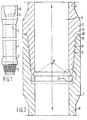
- pipe section 1 having a throughbore 2 is provided with a pin element 3 and a box element 4.
- the elements 3 and 4 are provided with conical screw threads 5 and 6, respectively, for co-operation with adjoining identical pipe sections (not shown).
- Figure 2 shows pin element 3 of Figure 1 on a larger scale and in coupled position with a box element 7 of an adjoining pipe section 8.
- Box element 7 is provided with a conical screw thread 9 and with an end shoulder 10 carrying an annular sealing ring 18, the shoulder and ring co-operating with an end shoulder 11 of the pin element 3 in the shown coupled position.
- pin element 3 is provided with an annular locking shoulder 12 arranged between the pin screw thread 5 and the free end 13 of pin element 3. Locking shoulder 12 co-operates in the shown coupled position with an annular locking shoulder 14 arranged on the box element 7.
- the locking shoulders 12 and 14 are conically shaped and are each formed by part of the surface of a cone having an apex with an angle a (see Figure 2) positioned on the coinciding longitudinal axes A-A of the pin and box elements, and pointing away from the free end 13 of the pin element 3 in the shown coupled position.
- a the width of the overlapping part of the locking shoulders 12 and 14 in the coupled position is indicated by "w”.
- the locking shoulders 12 and 14 adjoin guiding means 15 and 16 respectively.
- These guiding means 15 and 16 are conically shaped and are each formed by part of the surface of a cone having an apex (not shown) on the coinciding longitudinal axes A-A of the coupled pin and box elements.
- the inner wall of pin element 3 is furthermore provided with an annular groove 17 that allows flexion of the building means 15 as will be explained in more detail hereinafter.
- the pin element 3 is stabbed into the box element 7 until the lower end of screw thread 5 of the pin element 3 engages screw thread 9 of the box element 7, whereupon the pin element 3 is rotated to screw the elements 3 and 7 together.
- the guiding surface 1 5 of pin element 3 contacts guiding surface 16, further rotation will cause guiding surface 15 and consequently locking shoulder 12 to flex inwardly for passing through the bore of the guiding surface 1 6 of the box element 7. This inward flexion is enabled by the presence of annular groove 17.
- locking shoulder 12 and guiding surface 1 5 retain their original position, in which position the shoulder 12 mates with the locking shoulder 14.
- the end shoulders 10 and 11 are so arranged that as soon as the locking shoulder 12 comes in contact with the locking shoulder 14, the end shoulders 10 and 11 will engage each other tightly, in which position sealing ring 18 will avoid leakage of the coupling.
- the apex angle of the conically shaped locking shoulders 12 and 14 is so chosen that the coupling is locked against loosening by impacts exerted thereon, but can still be broken (if required) by exerting a predetermined torque on one of the elements (such as the pin element) whilst the other element is held against rotation.
- the conical screw thread 5 will then exert an upwardly directed force on the locking shoulder 12 of the pin element 3. Due to the conical shape of the locking shoulders 12 and 14, this upwardly directed force will cause locking shoulder 12 to slide over locking shoulder 14 whereby the shoulder 12 and the adjoining guiding surface 15 are flexed inwardly with respect to the bore of the pin element.
- shoulder 12 and guiding surface 15 will pass through the bore of the conically shaped guiding surface 16 of the box element 7 and subsequently through the conical screw thread 9 of the box element 7, thereby leaving the box element 7.
- Figures 4-6 show an alternative of the coupling shown in Figures 2 and 3.
- This alternative embodiment of the invention is provided with a number of slits 20, instead of with the annular groove 17 as shown in Figures 2 and 3.
- the slits 20 are so arranged that they divide the lower end of pin element 3 into a number of extensions 21 each carrying part of the locking shoulder 12 and part of guiding surface 15 of the pin element 3.
- the slits 20 run substantially parallel to the longitudinal axis A-A of the pin element 3, and pass through the locking shoulder 12 thereof, thereby allowing the guiding surface 15 and locking shoulder 1.2 to flex inwardly for passing over the guiding surface 16 during the coupling or uncoupling operation, which takes place in the same manner as described with reference to the coupling shown in Figures 2 and 3.
- the apex angle ⁇ may be chosen from a wide range of apex angles to obtain locking of the coupling against impacts but simultaneously allowing breaking of the coupling by exerting a predetermined torque thereon.
- a suitable range of apex anges a is between 50 and 150 degrees.
- width w depends upon a number of factors, such as the resiliency of the material of the pin element, the dimensions of the elements, and the required resistance against axial impacts.
- a suitable range of values from which the width w may be chosen is between 0.2 and 1.5 mm.
- the invention is not restricted to the application of a single pair of locking shoulders, although in the majority of cases a single pair will be sufficient for the purpose of locking the coupling against loosening when impacts are exerted thereon.
- the invention is not restricted to couplings having locking shoulders arranged between the co-operating conical screw threads and the free end of the pin element in the coupled position thereof.
- An arrangement wherein the coupling has locking shoulders in the coupled position thereof arranged between the co-operating conical screw threads 5 and 9 and the end shoulders 10 and 11 may also be applied advantageously.
- the pin element may be provided with an annular groove 17 (see Figure 3) in combination with slits 20 (see Figure 4) for obtaining the desired resiliency of the pin element. It will be appreciated that in the case where the pin element and/or the box element are sufficiently resilient for the purpose, the annular groove and/or the slits may be omitted.
- end shoulders 10 and 11 and sealing ring 18, shown in Figures 2 and 4 may be replaced by other suitable sealing members known per se and are therefore not described in detail.
Landscapes
- Engineering & Computer Science (AREA)
- General Engineering & Computer Science (AREA)
- Mechanical Engineering (AREA)
- Life Sciences & Earth Sciences (AREA)
- Geology (AREA)
- Mining & Mineral Resources (AREA)
- Physics & Mathematics (AREA)
- Environmental & Geological Engineering (AREA)
- Fluid Mechanics (AREA)
- General Life Sciences & Earth Sciences (AREA)
- Geochemistry & Mineralogy (AREA)
- Earth Drilling (AREA)
Claims (10)
Priority Applications (1)
| Application Number | Priority Date | Filing Date | Title |
|---|---|---|---|
| AT80201222T ATE8521T1 (de) | 1980-01-11 | 1980-12-19 | Kupplung zum verbinden von rohrteilstuecken und rohrteilstueck fuer tiefbohrungen. |
Applications Claiming Priority (2)
| Application Number | Priority Date | Filing Date | Title |
|---|---|---|---|
| GB8000989 | 1980-01-11 | ||
| GB8000989 | 1980-01-11 |
Publications (2)
| Publication Number | Publication Date |
|---|---|
| EP0032265A1 EP0032265A1 (fr) | 1981-07-22 |
| EP0032265B1 true EP0032265B1 (fr) | 1984-07-18 |
Family
ID=10510587
Family Applications (1)
| Application Number | Title | Priority Date | Filing Date |
|---|---|---|---|
| EP80201222A Expired EP0032265B1 (fr) | 1980-01-11 | 1980-12-19 | Raccord pour accoupler des sections de tube et section de tube pour opérations de forage |
Country Status (4)
| Country | Link |
|---|---|
| EP (1) | EP0032265B1 (fr) |
| AT (1) | ATE8521T1 (fr) |
| CA (1) | CA1148193A (fr) |
| DE (1) | DE3068630D1 (fr) |
Cited By (5)
| Publication number | Priority date | Publication date | Assignee | Title |
|---|---|---|---|---|
| US8544304B2 (en) | 2007-08-24 | 2013-10-01 | Tenaris Connections Limited | Method for improving fatigue resistance of a threaded joint |
| US8840152B2 (en) | 2010-03-26 | 2014-09-23 | Tenaris Connections Limited | Thin-walled pipe joint |
| US9004544B2 (en) | 2009-04-22 | 2015-04-14 | Tenaris Connections Limited | Threaded joint for tubes, pipes and the like |
| US9234612B2 (en) | 2007-06-22 | 2016-01-12 | Tenaris Connections Limited | Threaded joint with energizable seal |
| US9383045B2 (en) | 2007-07-16 | 2016-07-05 | Tenaris Connections Limited | Threaded joint with resilient seal ring |
Families Citing this family (20)
| Publication number | Priority date | Publication date | Assignee | Title |
|---|---|---|---|---|
| GB2248906B (en) * | 1990-10-16 | 1994-04-27 | Red Baron | A locking connection |
| WO1996035038A1 (fr) * | 1993-12-17 | 1996-11-07 | Sandvik Ab | Manchon filete, rallonges male et femelle et procede de maintien d'un manchon filete |
| FI974117A7 (fi) * | 1995-05-04 | 1997-11-03 | Sandvik Ab | Kierreliitos, uros- ja naarasjatkoselimet sekä menetelmä kierreliitoks en huoltamiseksi |
| SE515518C2 (sv) * | 1998-09-28 | 2001-08-20 | Uniroc Ab | Gängförband för borrsträng för slående bergborrning |
| FR2807095B1 (fr) * | 2000-03-31 | 2002-08-30 | Vallourec Mannesmann Oil & Gas | Element filete tubulaire delarde pour joint filete tubulaire resistant a la fatigue et joint filete tubulaire resultant |
| FR2874988B1 (fr) | 2004-09-09 | 2008-05-02 | Vallourec Mannesmann Oil & Gas | Element male pour un joint filete tubulaire etanche apres expansion diametrale |
| AT8404U1 (de) * | 2005-05-27 | 2006-07-15 | Techmo Entw & Vertriebs Gmbh | Rohrverbindung |
| EP2009340B1 (fr) | 2007-06-27 | 2010-12-08 | Tenaris Connections Aktiengesellschaft | Raccord fileté avec joint d'étanchéité pressurisable |
| EP2028403B1 (fr) | 2007-08-24 | 2011-04-13 | Tenaris Connections Aktiengesellschaft | Joint fileté doté de charges radiales élevées et de surfaces traitées différentiellement |
| EP2096253B1 (fr) | 2008-02-29 | 2010-06-16 | Tenaris Connections AG | Raccord fileté avec bagues d'étanchéité souples améliorées |
| EP2325435B2 (fr) | 2009-11-24 | 2020-09-30 | Tenaris Connections B.V. | Joint fileté étanche à des pressions internes et externes [extrêmement hautes] |
| US9163296B2 (en) | 2011-01-25 | 2015-10-20 | Tenaris Coiled Tubes, Llc | Coiled tube with varying mechanical properties for superior performance and methods to produce the same by a continuous heat treatment |
| BR112015016765A2 (pt) | 2013-01-11 | 2017-07-11 | Tenaris Connections Ltd | conexão de tubos de perfuração, tubo de perfuração correspondente e método para montar tubos de perfuração |
| US9803256B2 (en) | 2013-03-14 | 2017-10-31 | Tenaris Coiled Tubes, Llc | High performance material for coiled tubing applications and the method of producing the same |
| EP2789700A1 (fr) | 2013-04-08 | 2014-10-15 | DALMINE S.p.A. | Tuyaux en acier sans soudure trempé et revenu à paroi lourde et procédé de fabrication des tuyaux d'acier |
| EP2789701A1 (fr) | 2013-04-08 | 2014-10-15 | DALMINE S.p.A. | Tuyaux en acier sans soudure trempé et revenu à paroi moyenne haute résistance et procédé de fabrication des tuyaux d'acier |
| KR102197204B1 (ko) | 2013-06-25 | 2021-01-04 | 테나리스 커넥션즈 비.브이. | 고크롬 내열철강 |
| US20160305192A1 (en) | 2015-04-14 | 2016-10-20 | Tenaris Connections Limited | Ultra-fine grained steels having corrosion-fatigue resistance |
| US11124852B2 (en) | 2016-08-12 | 2021-09-21 | Tenaris Coiled Tubes, Llc | Method and system for manufacturing coiled tubing |
| US10434554B2 (en) | 2017-01-17 | 2019-10-08 | Forum Us, Inc. | Method of manufacturing a coiled tubing string |
Citations (4)
| Publication number | Priority date | Publication date | Assignee | Title |
|---|---|---|---|---|
| BE520079A (fr) * | 1952-05-31 | |||
| US1781091A (en) * | 1924-07-19 | 1930-11-11 | Nat Supply Co | Pipe joint |
| US2239942A (en) * | 1939-05-17 | 1941-04-29 | Hydril Company Of California | Well pipe joint |
| FR2379011A1 (fr) * | 1977-01-26 | 1978-08-25 | Hunting Oilfield Services Ltd | Raccord de tube |
Family Cites Families (1)
| Publication number | Priority date | Publication date | Assignee | Title |
|---|---|---|---|---|
| US3037797A (en) * | 1958-10-23 | 1962-06-05 | Cicero C Brown | Coupling devices |
-
1980
- 1980-11-27 CA CA000365647A patent/CA1148193A/fr not_active Expired
- 1980-12-19 EP EP80201222A patent/EP0032265B1/fr not_active Expired
- 1980-12-19 AT AT80201222T patent/ATE8521T1/de not_active IP Right Cessation
- 1980-12-19 DE DE8080201222T patent/DE3068630D1/de not_active Expired
Patent Citations (4)
| Publication number | Priority date | Publication date | Assignee | Title |
|---|---|---|---|---|
| US1781091A (en) * | 1924-07-19 | 1930-11-11 | Nat Supply Co | Pipe joint |
| US2239942A (en) * | 1939-05-17 | 1941-04-29 | Hydril Company Of California | Well pipe joint |
| BE520079A (fr) * | 1952-05-31 | |||
| FR2379011A1 (fr) * | 1977-01-26 | 1978-08-25 | Hunting Oilfield Services Ltd | Raccord de tube |
Cited By (5)
| Publication number | Priority date | Publication date | Assignee | Title |
|---|---|---|---|---|
| US9234612B2 (en) | 2007-06-22 | 2016-01-12 | Tenaris Connections Limited | Threaded joint with energizable seal |
| US9383045B2 (en) | 2007-07-16 | 2016-07-05 | Tenaris Connections Limited | Threaded joint with resilient seal ring |
| US8544304B2 (en) | 2007-08-24 | 2013-10-01 | Tenaris Connections Limited | Method for improving fatigue resistance of a threaded joint |
| US9004544B2 (en) | 2009-04-22 | 2015-04-14 | Tenaris Connections Limited | Threaded joint for tubes, pipes and the like |
| US8840152B2 (en) | 2010-03-26 | 2014-09-23 | Tenaris Connections Limited | Thin-walled pipe joint |
Also Published As
| Publication number | Publication date |
|---|---|
| EP0032265A1 (fr) | 1981-07-22 |
| DE3068630D1 (en) | 1984-08-23 |
| CA1148193A (fr) | 1983-06-14 |
| ATE8521T1 (de) | 1984-08-15 |
Similar Documents
| Publication | Publication Date | Title |
|---|---|---|
| EP0032265A1 (fr) | Raccord pour accoupler des sections de tube et section de tube pour opérations de forage | |
| DE3519662C2 (fr) | ||
| US4040756A (en) | Drill rod thread form | |
| CA1084553A (fr) | Joint d'aboutement | |
| US6957704B2 (en) | Limit clamp for use with casing attachments | |
| US4105262A (en) | Releasable drill string stabilizer | |
| US4258804A (en) | Releasable drill string stabilizer | |
| US4344718A (en) | Cold weather coupling device | |
| DE2827597C2 (de) | Vorrichtung zum Zertrennen von Rohren in einem Bohrloch | |
| EP0087557B1 (fr) | Raccord de tuyaux pour tuyaux métalliques | |
| US3062568A (en) | Safety screw thread arrangement | |
| DE68923338T2 (de) | Hermetische Metallrohrverbindung. | |
| AU2017327626B2 (en) | Threaded joint | |
| US4600063A (en) | Double-taper slip-on drill string stabilizer | |
| WO2014093025A2 (fr) | Verrou anti-rotation à effet de rochet pour raccords filetés | |
| EP0686244B1 (fr) | Raccord de tuyauterie a filets cuneiformes imbriques sans queue d'aronde | |
| AU753562B2 (en) | Thread coupling for a drill string for percussive rock drilling | |
| GB2153027A (en) | Pipe connector | |
| EP0165996B1 (fr) | Connexion tubulaire | |
| EP0368795A1 (fr) | Connecteur de tuyau | |
| GB1583038A (en) | Screw thread connection for pin and box pipe joints | |
| EP0706624B1 (fr) | Dispositif permettant de poser de maniere etanche des tuyaux, des conduites et analogues | |
| DE636055T1 (de) | Ein werkzeugzusammenbau. | |
| US4989902A (en) | Ratcheting and threaded well connector | |
| US4902047A (en) | Thread connector anti-rotation device |
Legal Events
| Date | Code | Title | Description |
|---|---|---|---|
| PUAI | Public reference made under article 153(3) epc to a published international application that has entered the european phase |
Free format text: ORIGINAL CODE: 0009012 |
|
| AK | Designated contracting states |
Designated state(s): AT DE FR GB IT |
|
| 17P | Request for examination filed |
Effective date: 19811204 |
|
| ITF | It: translation for a ep patent filed | ||
| GRAA | (expected) grant |
Free format text: ORIGINAL CODE: 0009210 |
|
| AK | Designated contracting states |
Designated state(s): AT DE FR GB IT |
|
| REF | Corresponds to: |
Ref document number: 8521 Country of ref document: AT Date of ref document: 19840815 Kind code of ref document: T |
|
| REF | Corresponds to: |
Ref document number: 3068630 Country of ref document: DE Date of ref document: 19840823 |
|
| ET | Fr: translation filed | ||
| PG25 | Lapsed in a contracting state [announced via postgrant information from national office to epo] |
Ref country code: AT Effective date: 19841219 |
|
| PLBE | No opposition filed within time limit |
Free format text: ORIGINAL CODE: 0009261 |
|
| STAA | Information on the status of an ep patent application or granted ep patent |
Free format text: STATUS: NO OPPOSITION FILED WITHIN TIME LIMIT |
|
| 26N | No opposition filed | ||
| GBPC | Gb: european patent ceased through non-payment of renewal fee | ||
| PG25 | Lapsed in a contracting state [announced via postgrant information from national office to epo] |
Ref country code: FR Free format text: LAPSE BECAUSE OF NON-PAYMENT OF DUE FEES Effective date: 19850830 |
|
| PG25 | Lapsed in a contracting state [announced via postgrant information from national office to epo] |
Ref country code: DE Effective date: 19850903 |
|
| REG | Reference to a national code |
Ref country code: FR Ref legal event code: ST |
|
| PG25 | Lapsed in a contracting state [announced via postgrant information from national office to epo] |
Ref country code: GB Effective date: 19881118 |