EP0032371A1 - Aufhängevorrichtung für paneelartig verlegte Wärmetauscherrohrsysteme - Google Patents
Aufhängevorrichtung für paneelartig verlegte Wärmetauscherrohrsysteme Download PDFInfo
- Publication number
- EP0032371A1 EP0032371A1 EP81100017A EP81100017A EP0032371A1 EP 0032371 A1 EP0032371 A1 EP 0032371A1 EP 81100017 A EP81100017 A EP 81100017A EP 81100017 A EP81100017 A EP 81100017A EP 0032371 A1 EP0032371 A1 EP 0032371A1
- Authority
- EP
- European Patent Office
- Prior art keywords
- tube
- latch
- shoulder
- vertical
- tubes
- Prior art date
- Legal status (The legal status is an assumption and is not a legal conclusion. Google has not performed a legal analysis and makes no representation as to the accuracy of the status listed.)
- Granted
Links
- 239000000463 material Substances 0.000 claims description 4
- 230000000630 rising effect Effects 0.000 claims description 3
- 230000000694 effects Effects 0.000 claims description 2
- 230000000284 resting effect Effects 0.000 claims description 2
- 241000282472 Canis lupus familiaris Species 0.000 abstract 2
- 210000001331 nose Anatomy 0.000 abstract 1
- 229920000297 Rayon Polymers 0.000 description 3
- 241001080024 Telles Species 0.000 description 3
- 239000002964 rayon Substances 0.000 description 3
- 238000003466 welding Methods 0.000 description 3
- 244000245420 ail Species 0.000 description 1
- 210000003323 beak Anatomy 0.000 description 1
- 239000000567 combustion gas Substances 0.000 description 1
- 239000012530 fluid Substances 0.000 description 1
- 238000004519 manufacturing process Methods 0.000 description 1
- 238000012986 modification Methods 0.000 description 1
- 230000004048 modification Effects 0.000 description 1
- 210000000056 organ Anatomy 0.000 description 1
- 238000002360 preparation method Methods 0.000 description 1
- 238000003825 pressing Methods 0.000 description 1
- 238000004080 punching Methods 0.000 description 1
- 125000006850 spacer group Chemical group 0.000 description 1
- 230000035882 stress Effects 0.000 description 1
- 230000008646 thermal stress Effects 0.000 description 1
Images


Classifications
-
- F—MECHANICAL ENGINEERING; LIGHTING; HEATING; WEAPONS; BLASTING
- F28—HEAT EXCHANGE IN GENERAL
- F28F—DETAILS OF HEAT-EXCHANGE AND HEAT-TRANSFER APPARATUS, OF GENERAL APPLICATION
- F28F9/00—Casings; Header boxes; Auxiliary supports for elements; Auxiliary members within casings
- F28F9/007—Auxiliary supports for elements
- F28F9/013—Auxiliary supports for elements for tubes or tube-assemblies
Definitions
- the present invention relates to a device for attaching a panel of horizontal or gently sloping heat exchange tubes to vertical tubes or beams provided with longitudinal fins.
- Such panels have already been fixed using collars formed around the tubes carried and welded to the vertical tubes or beams; or using monobloc saddles placed between the tubes or the support beams and the tubes carried and welded on them; or using spacers formed from two parts sliding one inside the other, one of these parts being welded to vertical tubes or beams: the other part being welded to the carried tubes.
- Such attachment devices require careful preparation of the panel on the template and possibly a large number of welding operations.
- the connecting pieces formed between the vertical tubes or beams and the horizontal tubes often have relatively small contact sections with the horizontal tubes, so that they are then poorly cooled by the fluid circulating in them and that it can appear excessive thermal stresses on the part-tube connection which can cause the tube to rupture.
- there are vibrations in operation in the tube panel there are stress concentrations at the rigid connections between the carried tubes and the support, which can lead to tube ruptures.
- the object of the present invention is to remedy these drawbacks, and to provide a device for hanging such tube panels which does not require very careful positioning of the tubes on a template, which lends itself to simple and rapid fixing, practically without no welding operation, and which allows the use of relatively simple intermediate parts and not requiring high manufacturing precision.
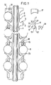
- Figure 1 shows in side view a few horizontal tubes of a panel fixed on the shoulders of the fins of a vertical tube, and a part forming a latch and a jumper separate from the device.
- FIG. 2 is an exploded perspective view of two tube supports, with parts forming a latch and jumpers, corresponding to the upper part of the device in FIG. 1.
- Figure 3 represents a side view of a few tubes, including two pairs of spacing greater than that of the others, corresponding to different parts of the panel, and the parts forming the corresponding latch.
- the vertical tube 1 comprises opposite welded vertical fins 2. These fins are cut by punching notches such as 3 t separating shoulders 4 with rim 5 projecting upwards.
- the latch 6 has a substantially flat upper face 7 on the side facing the vertical support tube, and rising on the other side according to a cylinder with a radius of curvature equal to that of a horizontal tube such as 8, so to oppose a detachment of the horizontal tube towards the outside.
- the width of the upper face 7 is determined in conjunction with the depth of the notches 2 ′ so that the tubes put in place come into contact with the bottom of the notches.
- the latch part is provided with a spout 9 separated from the middle part by a hollow 10 of width corresponding to that of the rim 5 of a shoulder 4, so as to be fit exactly on this one.
- It also includes a vertical sole 11 intended for apply against the rim of the shoulder 4, pierced in its lower part with a rectangular hole 12, and comprising on each side of this hole wings 13 intended to be applied on the two faces of the shoulders 4.
- These holes 12 are intended to allow the introduction of jumpers 14, which once placed in position come to rest by their legs on the upper periphery of the immediately lower horizontal tube.
- a lateral rim 15 of these jumpers is sufficiently pronounced to come into abutment on the lower part 16 of the corresponding shoulder, and thus to block the corresponding tube in the event of upward bias which would tend to unhook it during setting in. square.
- the jumpers 14 are not required to hold the tubes of the panel in place. They can be made of a combustible material at the temperature of the combustion gases coming into contact with the tube panel, and for example of plastic material.
- FIG. 3 represents a device for hooking tubes similar to that of FIGS. 1 and 2, but in an area where two adjacent tubes have a spacing greater than that of the other tubes, corresponding for example to the limit between two different parts of the panel of tubes.
- the parts forming a latch 6 are replaced at this height by parts 6A, comprising longer vertical flanges 11A, pressing against the shoulder flange 3A.
- Jumpers 14, identical to the others, are engaged in the holes 12, identical to those of the other parts forming a latch, of the parts 6A.
- the invention applies to the attachment of all panels of horizontal or slightly inclined, straight or helically low pitch heat exchange tubes.
Landscapes
- Engineering & Computer Science (AREA)
- Physics & Mathematics (AREA)
- Thermal Sciences (AREA)
- Mechanical Engineering (AREA)
- General Engineering & Computer Science (AREA)
- Heat-Exchange Devices With Radiators And Conduit Assemblies (AREA)
- Other Air-Conditioning Systems (AREA)
- Filling Or Discharging Of Gas Storage Vessels (AREA)
- Domestic Hot-Water Supply Systems And Details Of Heating Systems (AREA)
- Supports For Pipes And Cables (AREA)
- Steam Or Hot-Water Central Heating Systems (AREA)
Priority Applications (1)
| Application Number | Priority Date | Filing Date | Title |
|---|---|---|---|
| AT81100017T ATE3220T1 (de) | 1980-01-11 | 1981-01-05 | Aufhaengevorrichtung fuer paneelartig verlegte waermetauscherrohrsysteme. |
Applications Claiming Priority (2)
| Application Number | Priority Date | Filing Date | Title |
|---|---|---|---|
| FR8000582 | 1980-01-11 | ||
| FR8000582A FR2473697A1 (fr) | 1980-01-11 | 1980-01-11 | Dispositif d'accrochage d'un panneau de tubes d'echange de chaleur |
Publications (2)
| Publication Number | Publication Date |
|---|---|
| EP0032371A1 true EP0032371A1 (de) | 1981-07-22 |
| EP0032371B1 EP0032371B1 (de) | 1983-05-04 |
Family
ID=9237451
Family Applications (1)
| Application Number | Title | Priority Date | Filing Date |
|---|---|---|---|
| EP81100017A Expired EP0032371B1 (de) | 1980-01-11 | 1981-01-05 | Aufhängevorrichtung für paneelartig verlegte Wärmetauscherrohrsysteme |
Country Status (6)
| Country | Link |
|---|---|
| US (1) | US4356795A (de) |
| EP (1) | EP0032371B1 (de) |
| JP (1) | JPS56149594A (de) |
| AT (1) | ATE3220T1 (de) |
| DE (1) | DE3160205D1 (de) |
| FR (1) | FR2473697A1 (de) |
Families Citing this family (6)
| Publication number | Priority date | Publication date | Assignee | Title |
|---|---|---|---|---|
| FR2515331A1 (fr) * | 1981-10-23 | 1983-04-29 | Creusot Loire | Dispositif de fixation d'un faisceau de tubes notamment pour generateur de vapeur |
| FR2555722B1 (fr) * | 1983-11-25 | 1988-07-29 | Stein Industrie | Dispositif de suspension d'un faisceau de tubes horizontaux dans un plan vertical, et procede de fabrication de ce dispositif |
| FR2559248B1 (fr) * | 1984-02-03 | 1986-07-04 | Creusot Loire | Echangeur de chaleur a tubes |
| DE60027868T2 (de) * | 1999-01-29 | 2006-11-16 | L. & M. Radiator, Inc., Hibbing | Halterung für wärmetauscherrohre |
| EP2522943A1 (de) * | 2011-05-11 | 2012-11-14 | Borgwarner Emission Systems Spain, S.L. | Vorrichtung zur Verringerung der Vibrationen eines Rohrkerns eines Wärmetausches in seinem Gehäuse |
| US11035615B2 (en) * | 2018-08-23 | 2021-06-15 | Caterpillar Inc. | Support clip for finned tube type heat exchangers |
Citations (5)
| Publication number | Priority date | Publication date | Assignee | Title |
|---|---|---|---|---|
| US2204144A (en) * | 1935-10-31 | 1940-06-11 | Babcock & Wilcox Co | Fluid heat exchange apparatus |
| DE762698C (de) * | 1936-09-02 | 1954-06-14 | Mont Kessel Herpen & Co | Halterung fuer Rohre, die unmittelbar bestrahlt an den Feuerraumwaenden liegen |
| US2893698A (en) * | 1957-03-18 | 1959-07-07 | Babcock & Wilcox Co | Superheater tube support |
| US3354948A (en) * | 1965-10-21 | 1967-11-28 | Combustion Eng | Fluid cooled tube support and method of making same |
| US3378064A (en) * | 1966-05-12 | 1968-04-16 | Selas Corp Of America | Tube support |
Family Cites Families (2)
| Publication number | Priority date | Publication date | Assignee | Title |
|---|---|---|---|---|
| DE1145648B (de) * | 1959-11-17 | 1963-03-21 | Schmitz Rudolf | Vorrichtung zum Aufhaengen von Verdampfern u. dgl. bei Kuehlanlagen |
| GB1244611A (en) * | 1967-12-01 | 1971-09-02 | Atomic Power Constr Ltd | Improvements in or relating to heat exchangers |
-
1980
- 1980-01-11 FR FR8000582A patent/FR2473697A1/fr active Pending
-
1981
- 1981-01-05 DE DE8181100017T patent/DE3160205D1/de not_active Expired
- 1981-01-05 EP EP81100017A patent/EP0032371B1/de not_active Expired
- 1981-01-05 AT AT81100017T patent/ATE3220T1/de not_active IP Right Cessation
- 1981-01-08 JP JP160481A patent/JPS56149594A/ja active Granted
- 1981-01-08 US US06/223,534 patent/US4356795A/en not_active Expired - Lifetime
Patent Citations (5)
| Publication number | Priority date | Publication date | Assignee | Title |
|---|---|---|---|---|
| US2204144A (en) * | 1935-10-31 | 1940-06-11 | Babcock & Wilcox Co | Fluid heat exchange apparatus |
| DE762698C (de) * | 1936-09-02 | 1954-06-14 | Mont Kessel Herpen & Co | Halterung fuer Rohre, die unmittelbar bestrahlt an den Feuerraumwaenden liegen |
| US2893698A (en) * | 1957-03-18 | 1959-07-07 | Babcock & Wilcox Co | Superheater tube support |
| US3354948A (en) * | 1965-10-21 | 1967-11-28 | Combustion Eng | Fluid cooled tube support and method of making same |
| US3378064A (en) * | 1966-05-12 | 1968-04-16 | Selas Corp Of America | Tube support |
Also Published As
| Publication number | Publication date |
|---|---|
| JPS646400B2 (de) | 1989-02-03 |
| FR2473697A1 (fr) | 1981-07-17 |
| JPS56149594A (en) | 1981-11-19 |
| ATE3220T1 (de) | 1983-05-15 |
| DE3160205D1 (en) | 1983-06-09 |
| US4356795A (en) | 1982-11-02 |
| EP0032371B1 (de) | 1983-05-04 |
Similar Documents
| Publication | Publication Date | Title |
|---|---|---|
| EP0032371B1 (de) | Aufhängevorrichtung für paneelartig verlegte Wärmetauscherrohrsysteme | |
| EP0364920B1 (de) | Vorrichtung zur Aufhängung von horizontalen Warmeaustauscherrohren an ein vertikales Trägerrohr und Verfahren zur Herstellung | |
| FR2465044A1 (fr) | Dispositif de fixation de garde-corps et ensemble garde-corps en comportant application | |
| FR2529269A1 (fr) | Systeme d'assemblage elastique de deux pieces | |
| EP0767298B1 (de) | Befestigungsvorrichtung für einen Hochtemperatur-Wärmetauscher | |
| EP0088363B1 (de) | Vorrichtung zur Aufhängung von Rohrbündeln | |
| CH617526A5 (de) | ||
| EP0040112B1 (de) | Stahlwerkkonverter | |
| EP0014155A1 (de) | Gerüstbrett und Vorrichtung zur Montage dieses Brettes auf einem Gerüst | |
| EP2581119B1 (de) | Vorrichtung zur Befestigung eines Netzes mit einer Overlocknaht auf einem Träger | |
| FR2640035A1 (fr) | Dispositif de suspension d'un tube horizontal d'echange de chaleur sur un tube porteur vertical | |
| FR3062666A1 (fr) | Dispositif pour la fixation d'un potelet | |
| EP1013827A1 (de) | Schienenbefestigung | |
| EP0037789B1 (de) | Verbindungsstück zur 90 Grad-Zusammenstellung, insbesondere von rohrartigen Elementen mit kreisförmigem Querschnitt | |
| FR2640349A1 (fr) | Collier de fixation de tuyauteries | |
| FR2718335A1 (fr) | Elément de support notamment d'étagères. | |
| CH295347A (fr) | Etagère. | |
| FR2460412A3 (fr) | Dispositif d'accrochage, en particulier pour rendre solidaires plusieurs tables | |
| FR2525298A1 (fr) | Dispositif d'immobilisation axiale pour tige filetee, ecrou et produits faisant application de ce dispositif | |
| FR2561887A1 (fr) | Procede de montage d'elements mobiliers et taquet multifonctionnel adapte a ce montage | |
| EP0010015A1 (de) | Tür aus elastischen Streifen | |
| FR2642459A1 (fr) | Echafaudage demontable | |
| FR2711745A1 (fr) | Etrier réglable. | |
| JP2023058111A (ja) | 焼き網保持治具 | |
| FR2459441A1 (fr) | Grille support pour faisceau de tubes d'echange de chaleur |
Legal Events
| Date | Code | Title | Description |
|---|---|---|---|
| PUAI | Public reference made under article 153(3) epc to a published international application that has entered the european phase |
Free format text: ORIGINAL CODE: 0009012 |
|
| AK | Designated contracting states |
Designated state(s): AT BE CH DE FR GB IT NL SE |
|
| 17P | Request for examination filed |
Effective date: 19820107 |
|
| ITF | It: translation for a ep patent filed | ||
| GRAA | (expected) grant |
Free format text: ORIGINAL CODE: 0009210 |
|
| AK | Designated contracting states |
Designated state(s): AT BE CH DE FR GB IT LI NL SE |
|
| REF | Corresponds to: |
Ref document number: 3220 Country of ref document: AT Date of ref document: 19830515 Kind code of ref document: T |
|
| REF | Corresponds to: |
Ref document number: 3160205 Country of ref document: DE Date of ref document: 19830609 |
|
| PLBE | No opposition filed within time limit |
Free format text: ORIGINAL CODE: 0009261 |
|
| STAA | Information on the status of an ep patent application or granted ep patent |
Free format text: STATUS: NO OPPOSITION FILED WITHIN TIME LIMIT |
|
| 26N | No opposition filed | ||
| ITTA | It: last paid annual fee | ||
| EAL | Se: european patent in force in sweden |
Ref document number: 81100017.3 |
|
| PGFP | Annual fee paid to national office [announced via postgrant information from national office to epo] |
Ref country code: GB Payment date: 19981211 Year of fee payment: 19 |
|
| PGFP | Annual fee paid to national office [announced via postgrant information from national office to epo] |
Ref country code: FR Payment date: 19981215 Year of fee payment: 19 |
|
| PGFP | Annual fee paid to national office [announced via postgrant information from national office to epo] |
Ref country code: DE Payment date: 19981217 Year of fee payment: 19 |
|
| PGFP | Annual fee paid to national office [announced via postgrant information from national office to epo] |
Ref country code: SE Payment date: 19981223 Year of fee payment: 19 |
|
| PGFP | Annual fee paid to national office [announced via postgrant information from national office to epo] |
Ref country code: AT Payment date: 19981228 Year of fee payment: 19 |
|
| PGFP | Annual fee paid to national office [announced via postgrant information from national office to epo] |
Ref country code: CH Payment date: 19981229 Year of fee payment: 19 |
|
| PGFP | Annual fee paid to national office [announced via postgrant information from national office to epo] |
Ref country code: NL Payment date: 19981231 Year of fee payment: 19 |
|
| PGFP | Annual fee paid to national office [announced via postgrant information from national office to epo] |
Ref country code: BE Payment date: 19990111 Year of fee payment: 19 |
|
| PG25 | Lapsed in a contracting state [announced via postgrant information from national office to epo] |
Ref country code: AT Free format text: LAPSE BECAUSE OF NON-PAYMENT OF DUE FEES Effective date: 20000105 Ref country code: GB Free format text: LAPSE BECAUSE OF NON-PAYMENT OF DUE FEES Effective date: 20000105 |
|
| PG25 | Lapsed in a contracting state [announced via postgrant information from national office to epo] |
Ref country code: SE Free format text: LAPSE BECAUSE OF NON-PAYMENT OF DUE FEES Effective date: 20000106 |
|
| PG25 | Lapsed in a contracting state [announced via postgrant information from national office to epo] |
Ref country code: LI Free format text: LAPSE BECAUSE OF NON-PAYMENT OF DUE FEES Effective date: 20000131 Ref country code: BE Free format text: LAPSE BECAUSE OF NON-PAYMENT OF DUE FEES Effective date: 20000131 Ref country code: CH Free format text: LAPSE BECAUSE OF NON-PAYMENT OF DUE FEES Effective date: 20000131 |
|
| BERE | Be: lapsed |
Owner name: STEIN INDUSTRIE Effective date: 20000131 |
|
| PG25 | Lapsed in a contracting state [announced via postgrant information from national office to epo] |
Ref country code: NL Free format text: LAPSE BECAUSE OF NON-PAYMENT OF DUE FEES Effective date: 20000801 |
|
| GBPC | Gb: european patent ceased through non-payment of renewal fee |
Effective date: 20000105 |
|
| EUG | Se: european patent has lapsed |
Ref document number: 81100017.3 |
|
| REG | Reference to a national code |
Ref country code: CH Ref legal event code: PL |
|
| PG25 | Lapsed in a contracting state [announced via postgrant information from national office to epo] |
Ref country code: FR Free format text: LAPSE BECAUSE OF NON-PAYMENT OF DUE FEES Effective date: 20000929 |
|
| NLV4 | Nl: lapsed or anulled due to non-payment of the annual fee |
Effective date: 20000801 |
|
| PG25 | Lapsed in a contracting state [announced via postgrant information from national office to epo] |
Ref country code: DE Free format text: LAPSE BECAUSE OF NON-PAYMENT OF DUE FEES Effective date: 20001101 |
|
| REG | Reference to a national code |
Ref country code: FR Ref legal event code: ST |