EP0032450A2 - Segmente aufweisende Entladungsröhren - Google Patents
Segmente aufweisende Entladungsröhren Download PDFInfo
- Publication number
- EP0032450A2 EP0032450A2 EP81300120A EP81300120A EP0032450A2 EP 0032450 A2 EP0032450 A2 EP 0032450A2 EP 81300120 A EP81300120 A EP 81300120A EP 81300120 A EP81300120 A EP 81300120A EP 0032450 A2 EP0032450 A2 EP 0032450A2
- Authority
- EP
- European Patent Office
- Prior art keywords
- tube
- segments
- insulating material
- heat conductive
- electrically insulating
- Prior art date
- Legal status (The legal status is an assumption and is not a legal conclusion. Google has not performed a legal analysis and makes no representation as to the accuracy of the status listed.)
- Ceased
Links
Images

Classifications
-
- H—ELECTRICITY
- H01—ELECTRIC ELEMENTS
- H01S—DEVICES USING THE PROCESS OF LIGHT AMPLIFICATION BY STIMULATED EMISSION OF RADIATION [LASER] TO AMPLIFY OR GENERATE LIGHT; DEVICES USING STIMULATED EMISSION OF ELECTROMAGNETIC RADIATION IN WAVE RANGES OTHER THAN OPTICAL
- H01S3/00—Lasers, i.e. devices using stimulated emission of electromagnetic radiation in the infrared, visible or ultraviolet wave range
- H01S3/02—Constructional details
- H01S3/04—Arrangements for thermal management
- H01S3/041—Arrangements for thermal management for gas lasers
-
- H—ELECTRICITY
- H01—ELECTRIC ELEMENTS
- H01S—DEVICES USING THE PROCESS OF LIGHT AMPLIFICATION BY STIMULATED EMISSION OF RADIATION [LASER] TO AMPLIFY OR GENERATE LIGHT; DEVICES USING STIMULATED EMISSION OF ELECTROMAGNETIC RADIATION IN WAVE RANGES OTHER THAN OPTICAL
- H01S3/00—Lasers, i.e. devices using stimulated emission of electromagnetic radiation in the infrared, visible or ultraviolet wave range
- H01S3/02—Constructional details
- H01S3/03—Constructional details of gas laser discharge tubes
- H01S3/032—Constructional details of gas laser discharge tubes for confinement of the discharge, e.g. by special features of the discharge constricting tube
Definitions
- This invention relates to segmented gas discharge tube devices and in particular to segmented gas discharge tube devices for lasers.
- Such a discharge tube device has an envelope which contains a gas at pressure which is different from that of the environmental atmosphere and so the envelope is sealed so as to be isolated from the environmental atmosphere.
- the segments usually of circular section are made from a refractory material such as tungsten, tantalum, molybdenum, or graphite, and are mounted coaxially within a quartz tube which constitutes the major component of the envelope providing the isolation.
- the segments must be of a diameter which enables them to cool radiatively since in order to accomodate the differential thermal expansion the fit of a segment within the quartz tube is slack which precludes cooling by conduction through regions of contact between quartz and segment since these areas are too small.
- the metals tungsten, tantalum, and molybdenum are chosen because they can be heated to the temperatures necessary for radiative cooling (1200°K) but they are dense and not very resistant to sputtering.
- Use of graphite for segments has the disadvantage of producing dust which can lead to contamination of the laser window surfaces.
- segmented discharge tube devices as at present known tend to be heavy.and fragile or dusty and fragile and therefore require special precautions in packing, transport and use.
- the present invention seeks to provide an improved segmented discharge tube device in which the above difficulties are mitigated.
- a segmented discharge tube device comprises a plurality of electrically isolated metal segments presenting a passage through which plasma may pass, said segments being located in a tube with heat conductive electrically insulating material between the outer surfaces of said segments and adjacent inner surfaces areas of said tube.
- Said tube may itself be formed of a plurality of individual lengths, each containing a segment, in which case preferably said individual lengths are of Kovar or copper and said segments are of aluminium.
- said tube is formed of a continuous length of tube containing a plurality of segments, in which case preferably both said tube and said segments are of aluminium.
- Said heat conductive electrically insulating material may be provided either on each segment, or on the interior of the tube or individual lengths thereof, but preferably said material is provided both on each segment and on the interior of the tube or individual lengths thereof.
- said heat conductive electrically insulating material P.T.F.E. for example, but preferably, where the surface on which the material is provided is aluminium, said heat conductive electrically insulating material comprises anodisation and preferably again anodisation over which is provided a coating of high temperature polyimide varnish.
- a suitable varnish for this purpose is that available under the designation Pyre-M.L. Type RK-692.
- said material should have a thickness sufficient to provide electrical insulation but sufficiently thin as to allow the segments, as they are heated in operation by gas discharge along their axis, to cool by transmitting heat to the tube which, preferably, is arranged to be water cooled.
- said segments are fitted within said tube by shrink or expansion (of the tube) fitting during construction.
- said discharge tube device is provided with an anode having the form of a cylindrical sleeve fitted within said tube in an insulated fashion with heat conductive electrically insulating material between the outer surface of said sleeve and the adjacent inner surface area of said tube.
- said discharge tube device is provided with a cathode within a cathode shield which shield is fitted within said tube in an insulated fashion with heat conductive electrically insulating material between the outer surface of said cathode shield and the adjacent inner surface of said tube.
- said discharge tube device is a discharge tube of a laser.
- said segments and where appropriate said anode and cathode sleeves are insulated and spaced from one another by short cylindrical spacers of alumina.
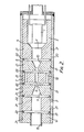
- the discharge tube device comprises a cathode 1 at one end and an anode 2 in the form of a cylindrical sleeve at the other end of the tube.
- the cathode 1 is enclosed within a cylindrical sleeve 3 the interior of which forms a cavity housing the cathode 1 with an outlet 4 having a taper 5.
- the cathode 1 and the anode 2 are a plurality of mutually insulated cylindrical segments of aluminium referenced 6, 7 and 8.
- An axial bore hole 9 passes through the centre of each of the segments 6, 7 and 8.
- the seqment 6 nearest the cathode 1 has a taper 10 leading into the axial bore hole 9 and segment 8 nearest the anode has a similar taper 11 leading out from the bore hole 9.
- the object of providing the tapers is to effect a smooth transition from regions of low current density to regions of high current density within the bore hole 9 and vice versa.
- the cathode cylindrical sleeve 3 the segments 6, 7 and 8 the anode sleeve 2 and an output cylindrical flange 12 (also of aluminium) are mutually spaced by alumina rings- 13.
- the separate parts of the device so far described are held together by Kovar sleeves 14 into which the aluminium components 3, 6, 7, 8, 2 and 12 are shrunk or expansion fitted.
- the sleeves 14 in effect form individual lengths of a tube.
- the outer surfaces of the aluminium components adjacent the inner surfaces of the sleeves 14 are prior to assembly anodised and the anodisation thus formed is covered by a coating of high temperature polyimide varnish.
- the aluminium components with their coatings of heat conductive electrically insulating material are cooled in liquid nitrogen and the thickness of each Kovar sleeve and the clearance between it and the aluminium component is chosen such that the expansive force exerted on the sleeve or aluminium component does not expand the sleeve in any way which would give the sleeve material an expansion co-efficient equivalent to that of the aluminium.
- an aluminium tube 15 Fitted within the output cylindrical flange 12 is an aluminium tube 15 which is shown broken away. To the left as viewed the tube 15 in practice continues to a T-junction (noxt shown) of which the "leg" is used for pumping during the normal conditioning process. Whilst not shown in the drawing the tube 15 ends in two flanges with sealing bellows between them with the second flange holding an output mirror. Surrounding the segmented tube and co-axial therewith is a water jacket 16 having a water inlet 17 and a water outlet 18 by means of which cooling water may be passed.
- Each intermediate segment 7 Whilst only one intermediate segment 7 is shown in practice there will usually be up to 50 or more, each similar. Each intermediate segment has gas return channels 19 located near the outer radius of the segment. The purpose of the intermediate segments is to confine the plasma which provides the amplification required for laser operation. Typically from a given diameter at the middle one of the intermediate segments, the bore diameters increase from segment to segment outwardly in both directions so that the diameter of the bore hole 9 is greater at either end than it is in the centre.
- the taper effect may be stepped (i.e. with the bore diameter in each segment a constant through that segment) or smoothly tapered throughout. The taper is designed to give propagation in the TEM oo mode.
- each intermediate segment The purpose of the two gas return channels such as 19 provided for each intermediate segment is to minimise the gas pumping effects occurring at each segment.
- the radial axes defined by the channels are arranged so that each axis is at 90° to the axis on its neighbouring segment in order to discourage the gas discharge from running down the channels instead of through the bore hole 9.
- the gaps between the segments are stepped so that the alumina rings 13 do not have a direct line of sight relationship with the plasma. In addition stepping the gaps between the segments provides shielding of the alumina rings 13 from charged particules.
- the cathode 1 is mounted within a cylindrical aluminium cathode sleeve 3.
- the anode 2 again consists of a cylindrical aluminium sleeve and between the cathode 1 and the anode 2 is a series of segments 6, 7 and 8. Again it will be noted that the outermost segments 6 and 8 have tapered entrances to the bore hole 9 and again whilst only one intermediate section 7 is shown in practice there will usually be many more arranged serially, each having gas return channels 19 as previously described.
- the cathode sleeve 3, the anode sleeve 2 and the intermediate segments 6, 7 and 8 are all shrunk fitted within a common continuous aluminium tube 20.
- manufacture mounting of the aluminium components 2, 3, 6, 7 and 8 within the tube 20 would normally be carried out by cooling the components in liquid nitrogen.
- the anode sleeve 2 and the segments such as 6, 7 and 8 are anodised as known per se, and the anodisation covered with a high temperature polyimide varnish.
- Acting to space and insulate cathode sleeve 3 the anode sleeve 2 and the segments 6, 7 and 8 one from another are short cylindrical spacers 22 of alumina.
- the bore hole 9 may be tapered through the segments 6, 7 and 8 and the gaps between the cathode sleeve 3, the anode sleeve 2 and the segments 6, 7 and 8, staggered as previously described with reference to Figure 1.
Landscapes
- Physics & Mathematics (AREA)
- Electromagnetism (AREA)
- Engineering & Computer Science (AREA)
- Plasma & Fusion (AREA)
- Optics & Photonics (AREA)
- Lasers (AREA)
Applications Claiming Priority (2)
| Application Number | Priority Date | Filing Date | Title |
|---|---|---|---|
| GB8001240A GB2068162B (en) | 1980-01-15 | 1980-01-15 | Segmented discharge tube devices |
| GB8001240 | 1980-01-15 |
Publications (2)
| Publication Number | Publication Date |
|---|---|
| EP0032450A2 true EP0032450A2 (de) | 1981-07-22 |
| EP0032450A3 EP0032450A3 (de) | 1982-05-12 |
Family
ID=10510630
Family Applications (1)
| Application Number | Title | Priority Date | Filing Date |
|---|---|---|---|
| EP81300120A Ceased EP0032450A3 (de) | 1980-01-15 | 1981-01-13 | Segmente aufweisende Entladungsröhren |
Country Status (4)
| Country | Link |
|---|---|
| US (1) | US4403167A (de) |
| EP (1) | EP0032450A3 (de) |
| JP (1) | JPS56104484A (de) |
| GB (1) | GB2068162B (de) |
Cited By (1)
| Publication number | Priority date | Publication date | Assignee | Title |
|---|---|---|---|---|
| WO2003094199A1 (fr) | 2002-04-30 | 2003-11-13 | Hamamatsu Photonics K.K. | Tube a decharge de gaz |
Families Citing this family (4)
| Publication number | Priority date | Publication date | Assignee | Title |
|---|---|---|---|---|
| US5055979A (en) * | 1990-01-08 | 1991-10-08 | Bhk, Inc. | Gas discharge light source |
| GB2312323B (en) * | 1996-04-20 | 2000-06-14 | Eev Ltd | Collector for an electron beam tube |
| JP2002093598A (ja) * | 2000-07-11 | 2002-03-29 | Daihen Corp | プラズマ発生装置 |
| DE102015101511B3 (de) * | 2015-02-03 | 2016-04-07 | Heraeus Noblelight Gmbh | Vorrichtung zur Bestrahlung eines zylinderförmigen Substrats |
Family Cites Families (3)
| Publication number | Priority date | Publication date | Assignee | Title |
|---|---|---|---|---|
| US3599107A (en) * | 1968-11-25 | 1971-08-10 | Sperry Rand Corp | Thermally compensated laser discharge structure |
| CH522287A (de) * | 1970-04-13 | 1972-06-15 | Inst Angewandte Physik | Niederdruck-Gasentladungsrohr für Laser |
| US3848150A (en) * | 1973-03-14 | 1974-11-12 | Itt | Discharge lamp with baffle plates |
-
1980
- 1980-01-15 GB GB8001240A patent/GB2068162B/en not_active Expired
-
1981
- 1981-01-13 US US06/224,644 patent/US4403167A/en not_active Expired - Fee Related
- 1981-01-13 EP EP81300120A patent/EP0032450A3/de not_active Ceased
- 1981-01-14 JP JP455181A patent/JPS56104484A/ja active Pending
Cited By (2)
| Publication number | Priority date | Publication date | Assignee | Title |
|---|---|---|---|---|
| WO2003094199A1 (fr) | 2002-04-30 | 2003-11-13 | Hamamatsu Photonics K.K. | Tube a decharge de gaz |
| EP1551054A4 (de) * | 2002-04-30 | 2010-01-13 | Hamamatsu Photonics Kk | Gasentladungsröhre |
Also Published As
| Publication number | Publication date |
|---|---|
| US4403167A (en) | 1983-09-06 |
| EP0032450A3 (de) | 1982-05-12 |
| GB2068162A (en) | 1981-08-05 |
| JPS56104484A (en) | 1981-08-20 |
| GB2068162B (en) | 1984-01-04 |
Similar Documents
| Publication | Publication Date | Title |
|---|---|---|
| US3763442A (en) | Ion laser plasma tube cooling device and method | |
| US3753144A (en) | Gas laser structure | |
| US3705999A (en) | Gas discharge tube for a laser | |
| US4764932A (en) | Ion laser having direct liquid cooling of segmented discharge tube | |
| US3437950A (en) | Ion laser having a metal tube shrink-fitted onto the ceramic discharge tube | |
| US3394320A (en) | Gas lasers with improved capillary tube | |
| US5353293A (en) | Hybrid cooled ion laser | |
| US4752937A (en) | Gas laser and production process therefor | |
| US4403167A (en) | Segmented discharge tube devices | |
| US3427564A (en) | High-power ionized gas laser structure | |
| US2390578A (en) | Thermoelectric generator | |
| US3274429A (en) | High frequency electron discharge device with heat dissipation means | |
| US5117434A (en) | Metal vapor laser apparatus | |
| US4091230A (en) | Evaporation-cooled transmission line system | |
| US4750186A (en) | Sealed gas laser | |
| US4912719A (en) | Ion laser tube | |
| US4481633A (en) | Wet-jacket argon-ion laser | |
| US3449628A (en) | Plasma arc electrodes with anode heat shield | |
| EP0204541A2 (de) | Apparat mit Entladungsröhre | |
| EP0802557B1 (de) | Kollektor für eine Elektronenstrahlröhre | |
| US5497392A (en) | Segmented lasing tube for high temperature laser assembly | |
| US5025193A (en) | Beam collector with low electrical leakage | |
| US4930136A (en) | Segmented air cooled laser tube | |
| US4760584A (en) | Hearth support arrangement | |
| GB2126413A (en) | Discharge tubes |
Legal Events
| Date | Code | Title | Description |
|---|---|---|---|
| PUAI | Public reference made under article 153(3) epc to a published international application that has entered the european phase |
Free format text: ORIGINAL CODE: 0009012 |
|
| AK | Designated contracting states |
Designated state(s): CH DE FR IT NL SE |
|
| 17P | Request for examination filed |
Effective date: 19810812 |
|
| PUAL | Search report despatched |
Free format text: ORIGINAL CODE: 0009013 |
|
| AK | Designated contracting states |
Designated state(s): CH DE FR IT NL SE |
|
| STAA | Information on the status of an ep patent application or granted ep patent |
Free format text: STATUS: THE APPLICATION HAS BEEN REFUSED |
|
| 18R | Application refused |
Effective date: 19840601 |
|
| RIN1 | Information on inventor provided before grant (corrected) |
Inventor name: STRUDWICK, IAN ARTHUR Inventor name: MAITLAND, ARTHUR Inventor name: MENOWN, HUGH |