EP0032485B1 - Mécanisme zigzag - Google Patents
Mécanisme zigzag Download PDFInfo
- Publication number
- EP0032485B1 EP0032485B1 EP81850007A EP81850007A EP0032485B1 EP 0032485 B1 EP0032485 B1 EP 0032485B1 EP 81850007 A EP81850007 A EP 81850007A EP 81850007 A EP81850007 A EP 81850007A EP 0032485 B1 EP0032485 B1 EP 0032485B1
- Authority
- EP
- European Patent Office
- Prior art keywords
- zigzag
- motor
- holder
- rack
- pin
- Prior art date
- Legal status (The legal status is an assumption and is not a legal conclusion. Google has not performed a legal analysis and makes no representation as to the accuracy of the status listed.)
- Expired
Links
Images


Classifications
-
- D—TEXTILES; PAPER
- D05—SEWING; EMBROIDERING; TUFTING
- D05B—SEWING
- D05B19/00—Program-controlled sewing machines
- D05B19/02—Sewing machines having electronic memory or microprocessor control unit
- D05B19/12—Sewing machines having electronic memory or microprocessor control unit characterised by control of operation of machine
- D05B19/14—Control of needle movement, e.g. varying amplitude or period of needle movement
Definitions
- the present invention relates to a zigzag mechanism of a sewing machine.
- a frame of the mechanism is provided in the arm of the sewing machine and supports the pivoted needle bar holder by which the zigzag motions of the needle can be carried out.
- a presser foot and needle bar unit with a body in the form of an elongated frame with points of attachment at both ends is priorly known from the Swedish Patent Specification 370 732.
- the zigzag motion of the swingable needle bar holder of the unit is carried out in the usual way of mechanical sewing machines by means of a rotating curve disc and a follower transferring reciprocating movements to the needle bar holder.
- a feed regulating mechanism is described in the U.S. Specification US-A-4,145,938.
- Each module is readily assembled apart from the machine and may thereafter be affixed for co-operative interrelationship in the machine bed.
- a stepping motor is used as a code converter and controlled by a stitch code supplied by amplification circuits and automatic control devices of the said memory unit, as described in for instance the French Specification FR-A-2,391,303.
- Such a stepping motor and driving arrangements can according to the invention be joined to the needle bar unit into a complete, driving zigzag mechanism out of which the zigzag motions are directly obtained on output of drive signals from the amplification circuits.
- a composed unit of this kind can be assembled outside the machine and then placed directly in position at the assembly of the machine. It also represents an advantage from a service point, since a fault located in such a unit can easily be remedied by substituting the whole unit.
- a zigzag mechanism having these properties is closely defined in the characterizing part of claim 1.
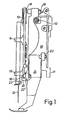
- a zigzag mechanism according to the invention is described in the following with references to the attached drawing which shows in Fig. 1 the zigzag mechanism in a side projection, Fig. 2 the same mechanism in a vertical projection mounted in a sewing machine, Fig. 3 the same mechanism in a perspective view.
- the body of the mechanism is constituted of a frame 10 which has a fixing lug 11 and holes for a through passing bar 12 by which the mechanism is secured to the machine.
- the needle bar guide is constituted of a holder 13 and bearings 14, 15 and keeps a movable needle bar 16, provided with a pivot 17 in a vertical position.
- the holder has a ball bearing 18 in the top of the frame 10 in which a through screw 19 is screwed and provided with a ball on which the holder is supported. It is then swingable sideways and controlled in its lower end by a guide rib 20 co-operating with a cam 21 on the frame.
- the frame is also, on one side, provided with fixing lugs 22, 23, where a stepping motor 24 is mounted.
- the shaft of the stepping motor is provided with a pinion 25 meshing with a rack 26 extended across the frame.
- the rack has approximately at the middle of it an aperture 27 forming a pair of sloping side edges 28, 29 making an obtuse angle, and a fixing point of a screw spring 30 at the remote end of the rack shown in the perspective view of Fig. 3.
- the screw spring is fixed to a lug 31 on the frame and acts upwards on the said remote end of the rack. That one is by a pin 32 on the holder 13 connected to the holder, which thereby will follow the motion of the rack.
- the pin is normally kept in the vertex of the obtuse angle as a consequence of the spring force acting on the remote end and the sloping of the edges 28, 29, but it may also slide onto someone of the edges. This may, e.g., occur when the needle 33 is subjected to an external, lateral force, but when this force ceases the pin will return to the vertex of the angle as the side edges slope that way.
- the pin is also a fulcrum of the rack which thus can rotate a little angle around the pin. This is possible by raising the forward end (the toothed end) of the rack above the pinion 25 so that this one is disengaged from the rack.
- the pinion is usually in mesh with the rack owing to the spring foce at its remote end, since the relative position between the rack and the pinion was adjusted at the assembly.
- a well-defined initial position of the stepping motor is very important in its function as a setting device for the lateral position of the needle, which is determined by the drive pulses supplied by the motor drive circuits.
- the rack and pinion it is possible to use a mechanical stop in the form of a dog 34 on the rack, whereby a stationary well-defined position is created.
- the setting of the motor to this position takes place so that the automatic control device in the machine emits a number of pulses to the input of the motor which cause the motor to step forwards to the stop. After such a series of pulses the motor is calibrated, that is to say it is set in the initial position.
- the motor When the drive circuits subsequently emit a series of pulses in the other direction, the motor responds in that it performs a corresponding number of steps from the initial position.
- a calibration can take place at suitable points of time in the working of the machine e.g. at the start of any fancy seam.
- the design of a rack has two purposes, first to bring about an elastic engagement between the motor and the needle bar holder which engagement is self-adjusting to the vertex of the obtuse angle in the aperture 27, and then to provide a calibration position at the stationary dog 34 from which the working range of the motor is counted.
- the transfer distance of the motion is short and the friction loss small which in combination with a small keeping torque of the needle bar holder in adjusted positions contributes to the possibility of using a relatively small stepping motor for the zigzag control.
- the aperture 27 may be positioned in the needle bar holder and the pin 32 on the rack.
Landscapes
- Engineering & Computer Science (AREA)
- Computer Hardware Design (AREA)
- Microelectronics & Electronic Packaging (AREA)
- Textile Engineering (AREA)
- Sewing Machines And Sewing (AREA)
Claims (2)
Applications Claiming Priority (2)
| Application Number | Priority Date | Filing Date | Title |
|---|---|---|---|
| SE8000309A SE423912B (sv) | 1980-01-15 | 1980-01-15 | Sicksackmekanism |
| SE8000309 | 1980-01-15 |
Publications (2)
| Publication Number | Publication Date |
|---|---|
| EP0032485A1 EP0032485A1 (fr) | 1981-07-22 |
| EP0032485B1 true EP0032485B1 (fr) | 1984-07-11 |
Family
ID=20339979
Family Applications (1)
| Application Number | Title | Priority Date | Filing Date |
|---|---|---|---|
| EP81850007A Expired EP0032485B1 (fr) | 1980-01-15 | 1981-01-14 | Mécanisme zigzag |
Country Status (3)
| Country | Link |
|---|---|
| EP (1) | EP0032485B1 (fr) |
| DE (1) | DE3164626D1 (fr) |
| SE (1) | SE423912B (fr) |
Families Citing this family (3)
| Publication number | Priority date | Publication date | Assignee | Title |
|---|---|---|---|---|
| US4398481A (en) * | 1981-07-23 | 1983-08-16 | Husqvarna Aktiebolag | Zigzag mechanism for a sewing machine |
| ES8505430A1 (es) * | 1984-07-26 | 1985-05-16 | Coser Alfa Maquinas | Perfeccionamientos introducidos en un mecanismo de zig-zag y transporte, para maquinas de coser |
| ES8701259A1 (es) * | 1986-02-03 | 1986-11-16 | Coser Alfa Maquinas | Maquina de coser perfeccionada |
Citations (2)
| Publication number | Priority date | Publication date | Assignee | Title |
|---|---|---|---|---|
| US3926133A (en) * | 1974-11-01 | 1975-12-16 | Singer Co | Sewing machine safety device |
| FR2391303A1 (fr) * | 1977-05-17 | 1978-12-15 | Husqvarna Ab | Machine a coudre avec moteur a etages regle en position initiale |
Family Cites Families (1)
| Publication number | Priority date | Publication date | Assignee | Title |
|---|---|---|---|---|
| US4145983A (en) * | 1978-06-26 | 1979-03-27 | The Singer Company | Feed regulating mechanism for a sewing machine |
-
1980
- 1980-01-15 SE SE8000309A patent/SE423912B/sv not_active IP Right Cessation
-
1981
- 1981-01-14 DE DE8181850007T patent/DE3164626D1/de not_active Expired
- 1981-01-14 EP EP81850007A patent/EP0032485B1/fr not_active Expired
Patent Citations (2)
| Publication number | Priority date | Publication date | Assignee | Title |
|---|---|---|---|---|
| US3926133A (en) * | 1974-11-01 | 1975-12-16 | Singer Co | Sewing machine safety device |
| FR2391303A1 (fr) * | 1977-05-17 | 1978-12-15 | Husqvarna Ab | Machine a coudre avec moteur a etages regle en position initiale |
Also Published As
| Publication number | Publication date |
|---|---|
| SE8000309L (sv) | 1981-07-16 |
| EP0032485A1 (fr) | 1981-07-22 |
| SE423912B (sv) | 1982-06-14 |
| DE3164626D1 (en) | 1984-08-16 |
Similar Documents
| Publication | Publication Date | Title |
|---|---|---|
| US4214540A (en) | Variable presser bar pressure control arrangement | |
| GB774294A (en) | Zig-zag control device for sewing machines | |
| US3978690A (en) | Selective positioning system particularly for controlling guide bars of knitting machines | |
| US4236839A (en) | Device for adjusting the height of a ribbon guide | |
| EP0032485B1 (fr) | Mécanisme zigzag | |
| EP0093145B1 (fr) | Mecanisme d'alimentation pour une machine a coudre | |
| US4191120A (en) | Stitch forming element control using _stepping motors which can be calibrated | |
| US4398481A (en) | Zigzag mechanism for a sewing machine | |
| JP4492162B2 (ja) | ミシンの糸調子装置 | |
| US6145457A (en) | Sewing machine having needle bar oscillating mechanism, needle bar interrupting mechanism and thread tension releasing mechanism | |
| US4236469A (en) | Sewing machine with feed dog dropping control system | |
| US4691654A (en) | Lateral movement feed dog for a sewing machine | |
| US4052946A (en) | Electronic control package for sewing machine | |
| US5769014A (en) | Ruffling device for mounting on a sewing machine | |
| US4436045A (en) | Differential feed mechanism for sewing machines | |
| US4183310A (en) | Feed and loop taker module for a sewing machine | |
| GB2142051A (en) | Sewing machine head end module construction | |
| US4188895A (en) | Needle bight control mechanism | |
| US4145983A (en) | Feed regulating mechanism for a sewing machine | |
| US5063867A (en) | Zigzag sewing machine | |
| US4644887A (en) | Sewing machine with revolving stitch regulator and display device | |
| US4448141A (en) | Sewing machine cam controlled feed engaging and disengaging mechanism | |
| US4147118A (en) | Combined electronic and mechanical pattern control for a sewing machine | |
| US4106419A (en) | Sewing machine | |
| US4677927A (en) | Electronic fancy sewing machine having means for adjusting the driving means of a cloth feeder during a feeding phase |
Legal Events
| Date | Code | Title | Description |
|---|---|---|---|
| PUAI | Public reference made under article 153(3) epc to a published international application that has entered the european phase |
Free format text: ORIGINAL CODE: 0009012 |
|
| AK | Designated contracting states |
Designated state(s): CH DE FR GB IT |
|
| 17P | Request for examination filed |
Effective date: 19820111 |
|
| ITF | It: translation for a ep patent filed | ||
| GRAA | (expected) grant |
Free format text: ORIGINAL CODE: 0009210 |
|
| AK | Designated contracting states |
Designated state(s): CH DE FR GB IT LI |
|
| REF | Corresponds to: |
Ref document number: 3164626 Country of ref document: DE Date of ref document: 19840816 |
|
| ET | Fr: translation filed | ||
| PLBE | No opposition filed within time limit |
Free format text: ORIGINAL CODE: 0009261 |
|
| STAA | Information on the status of an ep patent application or granted ep patent |
Free format text: STATUS: NO OPPOSITION FILED WITHIN TIME LIMIT |
|
| 26N | No opposition filed | ||
| PGFP | Annual fee paid to national office [announced via postgrant information from national office to epo] |
Ref country code: FR Payment date: 19900115 Year of fee payment: 10 |
|
| PGFP | Annual fee paid to national office [announced via postgrant information from national office to epo] |
Ref country code: CH Payment date: 19900116 Year of fee payment: 10 |
|
| ITTA | It: last paid annual fee | ||
| PGFP | Annual fee paid to national office [announced via postgrant information from national office to epo] |
Ref country code: GB Payment date: 19900131 Year of fee payment: 10 Ref country code: DE Payment date: 19900131 Year of fee payment: 10 |
|
| PG25 | Lapsed in a contracting state [announced via postgrant information from national office to epo] |
Ref country code: GB Effective date: 19910114 |
|
| PG25 | Lapsed in a contracting state [announced via postgrant information from national office to epo] |
Ref country code: LI Effective date: 19910131 Ref country code: CH Effective date: 19910131 |
|
| GBPC | Gb: european patent ceased through non-payment of renewal fee | ||
| PG25 | Lapsed in a contracting state [announced via postgrant information from national office to epo] |
Ref country code: FR Effective date: 19910930 |
|
| REG | Reference to a national code |
Ref country code: CH Ref legal event code: PL |
|
| PG25 | Lapsed in a contracting state [announced via postgrant information from national office to epo] |
Ref country code: DE Effective date: 19911001 |
|
| REG | Reference to a national code |
Ref country code: FR Ref legal event code: ST |