EP0032508B1 - Appareil de production de fibres minerales - Google Patents
Appareil de production de fibres minerales Download PDFInfo
- Publication number
- EP0032508B1 EP0032508B1 EP80901596A EP80901596A EP0032508B1 EP 0032508 B1 EP0032508 B1 EP 0032508B1 EP 80901596 A EP80901596 A EP 80901596A EP 80901596 A EP80901596 A EP 80901596A EP 0032508 B1 EP0032508 B1 EP 0032508B1
- Authority
- EP
- European Patent Office
- Prior art keywords
- bushing
- flange
- bottom wall
- added
- electrically conductive
- Prior art date
- Legal status (The legal status is an assumption and is not a legal conclusion. Google has not performed a legal analysis and makes no representation as to the accuracy of the status listed.)
- Expired
Links
- 238000004519 manufacturing process Methods 0.000 title claims abstract description 5
- 239000002557 mineral fiber Substances 0.000 title claims description 5
- 239000000835 fiber Substances 0.000 claims abstract description 10
- 239000004020 conductor Substances 0.000 claims abstract description 5
- 239000000463 material Substances 0.000 claims description 27
- 238000001816 cooling Methods 0.000 claims description 4
- 229910052500 inorganic mineral Inorganic materials 0.000 claims description 4
- 239000011707 mineral Substances 0.000 claims description 4
- 230000002238 attenuated effect Effects 0.000 claims description 3
- 239000003365 glass fiber Substances 0.000 abstract description 6
- 239000006060 molten glass Substances 0.000 abstract description 2
- 239000011521 glass Substances 0.000 description 5
- 238000010276 construction Methods 0.000 description 4
- BASFCYQUMIYNBI-UHFFFAOYSA-N platinum Chemical compound [Pt] BASFCYQUMIYNBI-UHFFFAOYSA-N 0.000 description 2
- 229910001260 Pt alloy Inorganic materials 0.000 description 1
- 229910000629 Rh alloy Inorganic materials 0.000 description 1
- 230000002411 adverse Effects 0.000 description 1
- 238000010438 heat treatment Methods 0.000 description 1
- 229910052751 metal Inorganic materials 0.000 description 1
- 239000002184 metal Substances 0.000 description 1
- 238000012986 modification Methods 0.000 description 1
- 230000004048 modification Effects 0.000 description 1
- 239000011819 refractory material Substances 0.000 description 1
- XLYOFNOQVPJJNP-UHFFFAOYSA-N water Substances O XLYOFNOQVPJJNP-UHFFFAOYSA-N 0.000 description 1
Images


Classifications
-
- C—CHEMISTRY; METALLURGY
- C03—GLASS; MINERAL OR SLAG WOOL
- C03B—MANUFACTURE, SHAPING, OR SUPPLEMENTARY PROCESSES
- C03B37/00—Manufacture or treatment of flakes, fibres, or filaments from softened glass, minerals, or slags
- C03B37/08—Bushings, e.g. construction, bushing reinforcement means; Spinnerettes; Nozzles; Nozzle plates
- C03B37/083—Nozzles; Bushing nozzle plates
-
- C—CHEMISTRY; METALLURGY
- C03—GLASS; MINERAL OR SLAG WOOL
- C03B—MANUFACTURE, SHAPING, OR SUPPLEMENTARY PROCESSES
- C03B37/00—Manufacture or treatment of flakes, fibres, or filaments from softened glass, minerals, or slags
- C03B37/08—Bushings, e.g. construction, bushing reinforcement means; Spinnerettes; Nozzles; Nozzle plates
- C03B37/09—Bushings, e.g. construction, bushing reinforcement means; Spinnerettes; Nozzles; Nozzle plates electrically heated
- C03B37/091—Indirect-resistance heating
-
- Y—GENERAL TAGGING OF NEW TECHNOLOGICAL DEVELOPMENTS; GENERAL TAGGING OF CROSS-SECTIONAL TECHNOLOGIES SPANNING OVER SEVERAL SECTIONS OF THE IPC; TECHNICAL SUBJECTS COVERED BY FORMER USPC CROSS-REFERENCE ART COLLECTIONS [XRACs] AND DIGESTS
- Y10—TECHNICAL SUBJECTS COVERED BY FORMER USPC
- Y10S—TECHNICAL SUBJECTS COVERED BY FORMER USPC CROSS-REFERENCE ART COLLECTIONS [XRACs] AND DIGESTS
- Y10S65/00—Glass manufacturing
- Y10S65/04—Electric heat
Definitions
- the invention relates to apparatus for producing fibres from heat softened mineral material, such as glass. More specifically, this invention relates to means of establishing desired current flow patterns or distribution within a fiber forming bushing to improve the heat uniformity within the bushing body.
- the current patterns within a bushing are established by the resistance of the various parts of the bushing, that is, the orifice plate, sidewalls, etc....
- An object of the invention is an improved apparatus for the production of mineral fibers.
- such apparatus comprises an electrically heated bushing comprising a bottom wall having orifices for the supply of streams of molten mineral material, to be attenuated into fibers, upwardly extending end walls having electrical terminals extending therefrom and upwardly extending sidewalls having outwardly extending flanges, and is characterized in that an electrically conductive material is added to the flanges to modify the electrical resistance of a portion of the flanges to establish a desired electrical flow distribution in the bottom wall.
- apparatus of the invention has particular utility in the processing of glass for forming fibers or filaments, it is to be understood that the apparatus may be employed for producing fibers from other materials.
- FIG. 1 illustrates a fiber forming operation.
- Mineral material such as glass
- the streams of glass form cones 24 at the discharge end of the orificed projections.
- Glass fibers 26 are attenuated from the cones of molten glass.
- the fibers are coated by size applicator 40 and gathered into a strand by gathering shoe 44.
- the strand is then collected by winder assembly 50.
- the strand is reciprocated by traverse 58 for collection on the winder collet 52 into a package 56.
- blower means 30 is provided. It is also within the scope of the present invention to use conventional fin shield glass fiber forming environment control apparatus rather than the blower apparatus shown.
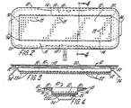
- the bushing assembly of FIG. 1 is shown in greater detail in FIGS. 2 through 4.
- the bushing chamber comprises a bottom wall 12 with perforations 21, upwardly extending end walls 32 and upwardly extending sidewalls 14.
- the end walls have electrical terminals 34 extending therefrom.
- the sidewalls each have an outwardly extending flange 16 at the upper edge thereof.
- the bushing bottom wall, end walls, sidewalls, and flanges are constructed of an electrically conductive metal such as a platinum/rhodium alloy.
- the bushing is provided with means for establishing a desired electrical current flow pattern through the flange to establish the electrical current flow pattern of the bottom wall and sidewalls.
- the addition of material to the flange modifies the current flow distribution such that relatively more current flows through the corner regions and relatively less current flows through the central region of the bottom wall. By such modification the heat pattern of the bottom wall is controlled to that desired.
- FIG. 2 shows electrically conductive material 18 that has been added to only a portion of each flange 16 to lower the electrical resistance of said portion.
- the material is added only to the outer area of each flange along the central region of the length of said flange.
- the shape of the ends of the material is designed to avoid hot spots. A tapered shape as shown can be used.
- the material 18 is positioned on the bottom surface of the flange although it could be on the upper surface or made an integral part thereof.
- cooling means 20 Adjacent the bottom surface of the material and the flange is cooling means 20.
- the cooling means can be a water cooled tube which conveys excess heat away from the outer edges of the flange to prevent glass from leaking from the bushing during operation.
- the cooling means removes any excess heat from the flange and material so that such heat does not adversely affect the bottom wall heat pattern by conduction of heat from the flange and material through the refractory material surrounding the bushing to the sidewalls and bottom wall.
- FIG. 5 illustrates an electrical current flow pattern in a prior art bushing.
- the current flows from terminal 34 of end wall 32 through bottom wall 12, sidewalls 14 and flanges 16 to the terminal at the other end of the bushing.
- the current flow in the corner region of the prior art bushing bottom wall and in the end regions of the sidewalls at the end wall region is small. Since the current flow is small, the heat generated in these areas will also be less than that in other areas of the bushing. This can result in cooler areas in the bushing, and thus, poor bushing performance. Cooler areas in a bushing can also result in production interruptions.
- FIG. 6 illustrates an electrical current flow pattern in a bushing resulting from use of the present invention.
- the current flows from terminal 34 of end wall 32 through bottom wall 12, sidewalls 14 and flanges 16 to the terminal at the other end wall of the bushing.
- the current flow illustrated in FIG. 6 is quite different from that shown in FIG. 5. This difference in current flow is due to the conductive material 18 added to a portion of each side wall flange. Material 18 reduces the electrical resistance at the center portion of the outside of the flange, and thus, additional current flows from the terminal through the corner regions of the bottom wall and the end regions of the sidewalls. This increased current flow results in improved bushing heat patterns.
- the bushing is generally of the same configuration as shown in FIGS. 1-4.
- the flange along the length of the bushing is about 43 centimeters in length and about 3 centimeters in width.
- the sidewalls and flanges are both about 0.05 centimeters in thickness.
- the material added to the center, outside region of the bottom of the flange is shaped as shown in FIG. 2.
- the ends of the material are tapered to avoid hot spots during operation.
- the material is about 30 centimeters in length at its longest portion and about 18 centimeters in length at its shortest portion.
- the material is about 1 centimeter in width and has a thickness of about 0.06 centimeter. With such a construction the bushing has an electrical current flow distribution as shown in FIG. 6.
- the added material does not extend the length of the flange. If the material extended the length of the flange, or if the flange were merely widened, or if the flange were merely thickened uniformly, the current flow pattern would not be as shown in FIG. 6.
- the present invention would be useful in the mineral fiber forming art and, in particular, in the glass fiber forming art.
Landscapes
- Engineering & Computer Science (AREA)
- Chemical & Material Sciences (AREA)
- Life Sciences & Earth Sciences (AREA)
- General Life Sciences & Earth Sciences (AREA)
- Geochemistry & Mineralogy (AREA)
- Manufacturing & Machinery (AREA)
- Materials Engineering (AREA)
- Organic Chemistry (AREA)
- Manufacture, Treatment Of Glass Fibers (AREA)
Abstract
Claims (4)
Applications Claiming Priority (2)
| Application Number | Priority Date | Filing Date | Title |
|---|---|---|---|
| US61572 | 1979-07-30 | ||
| US06/061,572 US4272271A (en) | 1979-07-30 | 1979-07-30 | Apparatus for production of mineral fibers |
Publications (3)
| Publication Number | Publication Date |
|---|---|
| EP0032508A1 EP0032508A1 (fr) | 1981-07-29 |
| EP0032508A4 EP0032508A4 (fr) | 1981-11-25 |
| EP0032508B1 true EP0032508B1 (fr) | 1984-05-16 |
Family
ID=22036651
Family Applications (1)
| Application Number | Title | Priority Date | Filing Date |
|---|---|---|---|
| EP80901596A Expired EP0032508B1 (fr) | 1979-07-30 | 1981-02-24 | Appareil de production de fibres minerales |
Country Status (7)
| Country | Link |
|---|---|
| US (1) | US4272271A (fr) |
| EP (1) | EP0032508B1 (fr) |
| JP (1) | JPS56500931A (fr) |
| BE (1) | BE884524A (fr) |
| CA (1) | CA1160453A (fr) |
| DE (1) | DE3067819D1 (fr) |
| WO (1) | WO1981000403A1 (fr) |
Families Citing this family (18)
| Publication number | Priority date | Publication date | Assignee | Title |
|---|---|---|---|---|
| US4516995A (en) * | 1984-07-20 | 1985-05-14 | Owens-Corning Fiberglas Corporation | Apparatus for forming glass fibers |
| US4594087A (en) * | 1985-04-01 | 1986-06-10 | Ppg Industries, Inc. | Three-terminal controller for fiber glass bushing |
| US4740224A (en) | 1986-01-17 | 1988-04-26 | Manville Corporation | Terminal connection for fiber glass bushing |
| US4634460A (en) * | 1986-01-17 | 1987-01-06 | Manville Service Corporation | Drain bushing |
| US4717411A (en) * | 1986-05-06 | 1988-01-05 | Manville Corporation | Drain bushing |
| KR100384050B1 (ko) * | 1994-10-12 | 2003-08-21 | 어드밴스트 글래스파이버 얀스, 엘엘씨 | 유리섬유부쉬세그먼트에서가열및냉각을제어하는방법및장치 |
| DE19948634B4 (de) * | 1999-10-01 | 2005-02-03 | Reeßing, Friedrich, Dr.rer.nat. | Konditioniereinrichtung für geschmolzenes Glas mit optimierter elektrischer Beheizung und verbesserter thermischer Homogenität des Glases |
| US6427492B1 (en) | 2000-03-31 | 2002-08-06 | Owens Corning Fiberglas Technology, Inc. | Bushing including a terminal ear |
| US7003986B2 (en) * | 2002-03-06 | 2006-02-28 | Johns Manville International, Inc. | Fiberizing bushings and methods of using |
| US20030034137A1 (en) * | 2002-07-19 | 2003-02-20 | Neogi Amar N. | Superabsorbent cellulosic fiber |
| EP1943572A2 (fr) | 2005-10-31 | 2008-07-16 | PPG Industries Ohio, Inc. | Procedes et systemes de regulation de la temperature d'une douille |
| US7726155B2 (en) * | 2006-07-07 | 2010-06-01 | Johns Manville | Cooling apparatus for fiberizing bushings |
| RU2369569C1 (ru) * | 2008-04-18 | 2009-10-10 | Общество с ограниченной ответственностью "Каменный Век" | Способ получения непрерывного волокна из горных пород, установка для его осуществления и получаемый продукт |
| RU2407711C1 (ru) * | 2009-06-09 | 2010-12-27 | Государственное образовательное учреждение высшего профессионального образования "Юго-Западный государственный университет"(ЮЗГУ) | Многофильерный питатель для изготовления непрерывного волокна из расплава горных пород |
| US20110146351A1 (en) * | 2009-12-23 | 2011-06-23 | Harms Todd M | Method and apparatus for directly forming continuous glass filaments |
| JP5672951B2 (ja) * | 2010-10-26 | 2015-02-18 | 日本電気硝子株式会社 | ブッシング |
| WO2014001173A1 (fr) * | 2012-06-26 | 2014-01-03 | Umicore Ag & Co. Kg | Plaque de base |
| RU2702439C1 (ru) * | 2019-01-30 | 2019-10-08 | Федеральное государственное бюджетное образовательное учреждение высшего образования "Юго-Западный государственный университет" (ЮЗГУ) | Многофильерный питатель для изготовления непрерывного волокна из расплава горных пород |
Family Cites Families (5)
| Publication number | Priority date | Publication date | Assignee | Title |
|---|---|---|---|---|
| US3512948A (en) * | 1967-03-23 | 1970-05-19 | Owens Corning Fiberglass Corp | Apparatus for processing heat-softened mineral material |
| US3511916A (en) * | 1967-03-29 | 1970-05-12 | Johns Manville | Electric resistance bushing for forming glass fibers |
| US3920429A (en) * | 1974-05-28 | 1975-11-18 | Owens Corning Fiberglass Corp | Stream feeder for making glass fibers |
| US4043778A (en) * | 1975-06-16 | 1977-08-23 | Johns-Manville Corporation | Electric resistance bushing for melting inorganic materials |
| SU635054A1 (ru) * | 1976-02-16 | 1978-11-30 | Беличское Научно-Производственное Объединение "Теплозвукоизоляция" | Стеклоплавильный сосуд |
-
1979
- 1979-07-30 US US06/061,572 patent/US4272271A/en not_active Expired - Lifetime
-
1980
- 1980-06-12 WO PCT/US1980/000740 patent/WO1981000403A1/fr not_active Ceased
- 1980-06-12 DE DE8080901596T patent/DE3067819D1/de not_active Expired
- 1980-06-12 JP JP50192880A patent/JPS56500931A/ja active Pending
- 1980-06-16 CA CA000354113A patent/CA1160453A/fr not_active Expired
- 1980-07-29 BE BE0/201565A patent/BE884524A/fr not_active IP Right Cessation
-
1981
- 1981-02-24 EP EP80901596A patent/EP0032508B1/fr not_active Expired
Also Published As
| Publication number | Publication date |
|---|---|
| EP0032508A1 (fr) | 1981-07-29 |
| WO1981000403A1 (fr) | 1981-02-19 |
| DE3067819D1 (en) | 1984-06-20 |
| BE884524A (fr) | 1981-01-29 |
| EP0032508A4 (fr) | 1981-11-25 |
| JPS56500931A (fr) | 1981-07-09 |
| US4272271A (en) | 1981-06-09 |
| CA1160453A (fr) | 1984-01-17 |
Similar Documents
| Publication | Publication Date | Title |
|---|---|---|
| EP0032508B1 (fr) | Appareil de production de fibres minerales | |
| US4033742A (en) | Method for producing glass fibers | |
| US4026689A (en) | Apparatus for making glass fibers | |
| US2489508A (en) | Apparatus for producing fibers | |
| US3695858A (en) | Method and apparatus for production of glass fibers | |
| US3512948A (en) | Apparatus for processing heat-softened mineral material | |
| US3511916A (en) | Electric resistance bushing for forming glass fibers | |
| US2360373A (en) | Apparatus for feeding glass in the manufacture of fibers | |
| US2814657A (en) | Method and apparatus for heating glass | |
| US4207086A (en) | Stream feeder apparatus | |
| US4328015A (en) | Process for the manufacture of fibers | |
| US3328144A (en) | Apparatus for melting and processing heat-softenable mineral materials | |
| US4363645A (en) | Annular bushing for forming glass fibers | |
| US4398933A (en) | Method and apparatus for the manufacture of fibers | |
| US4285712A (en) | Apparatus and method for the production of glass fibers | |
| CA1279192C (fr) | Raccord pour filiere chauffee de fabrication de la fibre de verre | |
| US4272272A (en) | Method and apparatus for production of mineral fibers | |
| US3920429A (en) | Stream feeder for making glass fibers | |
| US3492104A (en) | Apparatus for making glass fibers | |
| CA1094321A (fr) | Regulation thermique pour le faconnage de fibre minerale | |
| US4055406A (en) | Apparatus for making glass fibers material | |
| US4161396A (en) | Method and apparatus for processing heat-softened fiber-forming material | |
| US3416906A (en) | Method and apparatus for processing heat-softened mineral material | |
| US3867118A (en) | Apparatus for production of glass fibers | |
| CA1118999A (fr) | Methode et installation de fabrication de la fibre de verre |
Legal Events
| Date | Code | Title | Description |
|---|---|---|---|
| PUAI | Public reference made under article 153(3) epc to a published international application that has entered the european phase |
Free format text: ORIGINAL CODE: 0009012 |
|
| 17P | Request for examination filed |
Effective date: 19801110 |
|
| AK | Designated contracting states |
Designated state(s): DE FR GB |
|
| GRAA | (expected) grant |
Free format text: ORIGINAL CODE: 0009210 |
|
| AK | Designated contracting states |
Designated state(s): DE FR GB |
|
| PGFP | Annual fee paid to national office [announced via postgrant information from national office to epo] |
Ref country code: FR Payment date: 19840613 Year of fee payment: 5 |
|
| REF | Corresponds to: |
Ref document number: 3067819 Country of ref document: DE Date of ref document: 19840620 |
|
| PGFP | Annual fee paid to national office [announced via postgrant information from national office to epo] |
Ref country code: DE Payment date: 19840628 Year of fee payment: 5 |
|
| ET | Fr: translation filed | ||
| PLBE | No opposition filed within time limit |
Free format text: ORIGINAL CODE: 0009261 |
|
| STAA | Information on the status of an ep patent application or granted ep patent |
Free format text: STATUS: NO OPPOSITION FILED WITHIN TIME LIMIT |
|
| 26N | No opposition filed | ||
| PG25 | Lapsed in a contracting state [announced via postgrant information from national office to epo] |
Ref country code: FR Free format text: LAPSE BECAUSE OF NON-PAYMENT OF DUE FEES Effective date: 19870227 |
|
| PG25 | Lapsed in a contracting state [announced via postgrant information from national office to epo] |
Ref country code: DE Effective date: 19870303 |
|
| REG | Reference to a national code |
Ref country code: FR Ref legal event code: ST |
|
| GBPC | Gb: european patent ceased through non-payment of renewal fee | ||
| PG25 | Lapsed in a contracting state [announced via postgrant information from national office to epo] |
Ref country code: GB Free format text: LAPSE BECAUSE OF NON-PAYMENT OF DUE FEES Effective date: 19881118 |