EP0032607B1 - Fahrpreisberechnungs- und Fahrdienstleitungsverfahren - Google Patents
Fahrpreisberechnungs- und Fahrdienstleitungsverfahren Download PDFInfo
- Publication number
- EP0032607B1 EP0032607B1 EP19800300185 EP80300185A EP0032607B1 EP 0032607 B1 EP0032607 B1 EP 0032607B1 EP 19800300185 EP19800300185 EP 19800300185 EP 80300185 A EP80300185 A EP 80300185A EP 0032607 B1 EP0032607 B1 EP 0032607B1
- Authority
- EP
- European Patent Office
- Prior art keywords
- time
- fare
- vehicle
- station
- vehicles
- Prior art date
- Legal status (The legal status is an assumption and is not a legal conclusion. Google has not performed a legal analysis and makes no representation as to the accuracy of the status listed.)
- Expired
Links
- 238000000034 method Methods 0.000 title claims description 25
- 238000004891 communication Methods 0.000 claims description 17
- 230000005540 biological transmission Effects 0.000 claims description 9
- 238000012544 monitoring process Methods 0.000 claims description 8
- 238000012937 correction Methods 0.000 claims description 7
- 238000004364 calculation method Methods 0.000 description 20
- 238000012545 processing Methods 0.000 description 7
- 230000006870 function Effects 0.000 description 6
- 238000010586 diagram Methods 0.000 description 4
- 230000008569 process Effects 0.000 description 4
- 238000004422 calculation algorithm Methods 0.000 description 3
- 238000007726 management method Methods 0.000 description 3
- 239000000872 buffer Substances 0.000 description 2
- 230000001276 controlling effect Effects 0.000 description 2
- 230000000881 depressing effect Effects 0.000 description 2
- 230000010365 information processing Effects 0.000 description 2
- 230000008520 organization Effects 0.000 description 2
- 230000004044 response Effects 0.000 description 2
- 238000012384 transportation and delivery Methods 0.000 description 2
- 230000009471 action Effects 0.000 description 1
- 238000013459 approach Methods 0.000 description 1
- 238000004590 computer program Methods 0.000 description 1
- 230000001419 dependent effect Effects 0.000 description 1
- 230000000994 depressogenic effect Effects 0.000 description 1
- 238000001514 detection method Methods 0.000 description 1
- 238000011161 development Methods 0.000 description 1
- 230000000694 effects Effects 0.000 description 1
- 230000004886 head movement Effects 0.000 description 1
- 238000012886 linear function Methods 0.000 description 1
- 230000007257 malfunction Effects 0.000 description 1
- 239000011159 matrix material Substances 0.000 description 1
- 238000012986 modification Methods 0.000 description 1
- 230000004048 modification Effects 0.000 description 1
- 230000000737 periodic effect Effects 0.000 description 1
- 238000013439 planning Methods 0.000 description 1
- 230000001105 regulatory effect Effects 0.000 description 1
- 230000008521 reorganization Effects 0.000 description 1
- 230000003068 static effect Effects 0.000 description 1
- 238000013517 stratification Methods 0.000 description 1
- 238000012360 testing method Methods 0.000 description 1
Images


Classifications
-
- G—PHYSICS
- G07—CHECKING-DEVICES
- G07B—TICKET-ISSUING APPARATUS; FARE-REGISTERING APPARATUS; FRANKING APPARATUS
- G07B13/00—Taximeters
Definitions
- the present invention relates to fare computation and dispatching methods or similar computational applications, being more particularly concerned with adapting taxi meters and the like to accommodate simultaneous and overlapping customers with varied pick-up and delivery locations, and with automatically provided sophistication and equitably proper control and/or corrections for such factors as time of day, traffic conditions, minimal routing and the like. While hereinafter described with reference to the illustrative and preferred application to taxi operations, it should be understood that the concepts and techniques here-involved may also be applied to other applications, as well, where the features or some of the features of the invention may also be desired.
- This article discloses a dial-a-ride system which lessens the burden of control room personnel and offers door-to-door service on demand using shared vehicles with dynamically changing routes.
- pick-ups and deliveries are relayed to the drivers via two-way mobile radios.
- the dispatcher in the control room who interrogates a computer to obtain the vehicle's next destination.
- the invention thus, introduces compensations and corrections based upon the particular routes and time of day with its differing traffic and similar circumstances, and, in addition, may select the most expeditious, economical or otherwise suitable routes for the driver to take consistent with the best service to the customer-again from centralized stored information elicited when the pick-up and destination points are communicated to the central computing and controlling head- quarters.
- a further object is to provide a technique whereby real-time indications may be provided to the central station of various taxicab mechanical data such as engine temperature, oil temperature and oil pressure, as well as such data as how many seats in the taxicab are occupied.
- a further object is to provide a system wherein emergency signals can be provided to the central station and which may be inconspicuously communicated by the taxicab operator to indicate, for example, that police aid is desired.
- a further object is to provide such a novel method and system that may be applicable to other vehicular and related control applications, as well, wherein advantages and functions similar to those attained by the invention in taxi usages may be desired.
- this invention embraces a method of fare computation and dispatching referred to herein as the Ride Shared Vehicle Paratransit System (RSVP System), and comprising storing information in a computer at a central control station relating to routes and distances between street addresses and historical data as to time for normal transit therebetween under different times of day and traffic conditions; peripherally interfacing with the central control station through communication links with moving vehicles; communicating pick-up and deposit addresses along such links to the central control station from each vehicle for each hire thereof; calculating fares and estimating times of transit using said stored information; characterised by transmitting along said links, said calculated fares and estimated times of transit selectively addressed to the corresponding vehicle; and receiving and automatically displaying said transmitted fares and times at the respective vehicles, the displaying step including simultaneously displaying pluralities of fare and corresponding time data at the vehicles transmitted for over- lapping hires.
- RVP System Ride Shared Vehicle Paratransit System
- the Central Control Station of Figure 1 serves as the focal point for all operations, which includes the following basic hardware components:
- the Operation Console 2b of the Central Computer 2a consisted of a hard copy terminal equipped with a paper tape reader/punch, used for entering programs and for monitoring computer operations. All programs were developed by using a disk based operating system with text editing capabilities; however, after development, the system programs function independently of the operating system.
- Secondary storage at 1 for the system was provided by a moving-head cartridge disk system containing one fixed disk and one removable disk cartridge, each of which had a 2.5 million word capacity.
- the disk system was completely compatible with DEC hardware and software.
- vendor software protection features permitted using the device to store operating system files in addition to storing the hash-coded Address-Coordinate File and the Time/Distance File.
- the Dispatch Console of the Central Control station 3a and 3b may be used to enter origin or pick-up and destination or deposit address data and to display operating information (e.g. fares, estimated trip times for each hire, system messages, vehicle messages).
- operating information e.g. fares, estimated trip times for each hire, system messages, vehicle messages.
- the Dispatch Console was the Cathode Ray Tube terminal 3a which stored up to 1920 characters (24 lines of 80 characters) and which had a protected field capability for display in prearranged screen formats.
- the computer interface for the Dispatch Console 3a and 3b and for the Operations Console 2b was a standard DEC DL11-E asynchronous line interface with modem control capability which permitted demonstrations at remote locations using voice grade telephone lines.
- Vehicle communications were routed through a special purpose interface with 64-bit (i.e. four word) input/output capability.
- the interface supported one or two base station transmitters and was capable of adequately communicating with up to 500 vehicles. Since a portion of the interface capacity may be unused, various system display functions may easily be added by connecting interface outputs to a stand-alone static display.-,-For example, the display could indicate emergency conditions without tying up the Operations Console 2b; and the before-mentioned Dispatch Console 3a functions may also be displayed thereon at the central station.
- the interfacing Command Module 4a and 4b interpret commands, execute commands, and control vehicle communications. They also format the Operations Console display at 3a, check input data for validity, and initialize internal buffers with valid data.
- the vehicle display may show the trip fare and estimated trip time of each hire generated by the Central Computer, or the fare as determined by the electronic meter in the event of a computer failure, the mode in which fares are calculated by computer being the normal operating mode and the electronic meter capability providing a manual back up.
- Trip and fare data are continuously accumulated and may be accessed manually or by the computer, with the meter distance fare rate and time fare rate being adjustable to accommodate virtually any fare rate structure.
- Digital radio transmission along the communications link between the central station and the vehicles may provide the means for computer- based control of the entire fleet, with communications and monitoring capabilities being expandable by incorporating micro-processor techniques.
- the vehicle. unit operates either in conventional taxi mode or the computer-controlled mode with the latter mode initiated after the digital carrier is detected and the vehicle has been addressed.
- the transmission along the radio communications link can then be either a system code or the display code.
- the display is activated with a flag button, though the-display, flag and hold buttons may all be simultaneously activated by a display on (DO) code immediately following the vehicle ID. This action locks out the backup meter.
- DO sets the display to 00/0000, and indicates that, for example, the next six words sent to the vehicle are the fare and trip time following by an EOM (End-of-message). (If the carrier has not been received for 50 milliseconds, an EOM is assumed).
- the fare display at 10 remains set until the vehicle operator turns the display off as by depressing the flag button. This will allow separate fares for each trip.
- the minute display begins to decrement as soon as DO (or vehicle addressed) is received.
- the normal meter mode can be initiated at any time by depressing the flag button so that, in the event of a communication or computer failure, the meter automatically provides back-up fare calculations.
- the meter unit 10, and speedometer cable (SC) sensor 8 form the basic vehicle meter, requiring input from the SC sensor and two clock frequencies such as (960 Hz and 1 Hz). It outputs fare increments and 1/10 mile pulses. Fare counters total the fare increments and drive the display unit. The 1/10 mile pulse is used to increment the complete daily (or monthly) mileage on the vehicle.
- the meter memory may contain the total 1/10 miles, the paid 1/10 miles, the number of flag drops (i.e. trips), the accumulated revenue collected in meter mode and the accumulated revenue collected in computer-controlled mode. Memory capacity may be expanded to permit additional monitoring and the meter memory may be read from the vehicle remotely via computer or with, for example, a key lock rotary selector switch. After the meter memory is read, it may be zeroed.
- the meter unit will permit fare rate structure adjustments using wire jumpers that determine the cents/minute, cents/mile, and threshold velocity (i.e. the point at which the instantaneous time fare rate is the same as the distance fare rate). Below the threshold velocity, fares are based on time; above, only on distance.
- the fare jumpers may be sealed to prevent unauthorized adjustments and may be located on the display processor/memory circuit board and set initially by switches.
- the communication and control hardware for a vehicle to be used in the taxi fleet operated under this mode may consist of a six digit display, electronic fare meter, and digital radio transmission equipment.
- the display shows the trip fare and estimated trip time generated by the Central Computer, or the fare determined by the electronic meter in the event of a computer failure.
- Trip and fare data are continuously accumulated in the meter, and may be accessed manually or by the computer and the meter may readily also be adjusted to accommodate virtually any fare structure.
- Digital radio transmission with unique vehicle addressing, error checking and command control capabilities, will permit efficient computer-assisted control of a taxi fleet.
- various other sensors may be used including oil pressure, amount of gas, engine temperature, engine vacuum, and other quantities that are good indicators of the vehicle's mechanical status, which can be reported to the base station.
- Other, more specialized sensors such as set switches to verify occupancy, or hidden panic switches to indicate an emergency by the driver, can be incorporated into the system. This real-time monitoring capability also permit regulatory. agencies to inspect a transit operation effectively from the base station using the monitor console.
- the display unit may, for example, utilize LED or incandescent two-digit displays for indicating time in minutes, four-digit displays for fares up to $99.99, the hold and flag buttons (which may be illuminated when depressed), and a communication keyboard.
- the vehicle identification numbers may be switch selectable on the vehicle FSK transmitter and receiver card.
- Each ID word in the tested system was two bytes long and contained one initial control code nibble and three ID number nibbles.
- the controlled code specified the function to be performed by the vehicle receiver.
- Identification numbers were encoded in binary coded decimal (BCD) format.
- ID numbers may be decoded on the receiver card by sequentially comparing the address bytes. If the first byte received matches the first bank of switches, the decoder is advanced, which in turn activates the second bank of switches. If the second byte matches, the vehicle addressed flag is set. Subsequent data will then be processed and the addressing cycle is completed. The addressed flag is cleared either by dropping the carrier for 50 milliseconds or by sending an end of message (EOM) code.
- EOM end of message
- the vehicle ID is encoded on a universal transmitter card (universal because it may be used for the base station as well).
- the transmitter may be set, by switches or by the computer, to transmit either two bytes for complete identification (contained in two words), or one byte.
- error, hardware malfunction, emergency, and data out flags are all tied into the first nibble out (switch bank 1, Bits 0-3), which ordinarily would be set to the address code.
- Sensing elements and status latches may be added to permit transmitting important status conditions as well as the ID number.
- the start and stop bits can be checked for data over/under run and message completeness, and the parity bit may be used to check data validity. If an error occurs after the addressing words have been received by the vehicle, an error flag is set and returned with the vehicle ID. Error flagging at the base station may be done visually and digitally.
- a vehicle printer may also be incorporated for printed receipts. In multi-origin/destination applications, the printer would also be used to differentiate between trips.
- the Dispatcher essentially acts as a switchboard by routing information to and from the interface.
- the status of interface output bits control the information flow.
- T Transmit
- the information is sent along the radio communications link in FSK format to the appropriate vehicle. If the message is received without error, the vehicle response consists of its ID alone. If, however, an error has occurred, an error code is returned with the vehicle ID, an error message is displayed on the CRT 3a, and the message is transmitted again.
- the basic software includes a vendor-supplied operating system and the Data Base Management System 13 of Figure 2.
- the system contains a control structure 13 which links processing modules and data files including:
- the Time/Distance File contains shortest-time-path distances, travel time during uncongested periods, and travel time during congested periods for trips between all possible pairs of traffic zones.
- the Address-Coordinate File associates state plane coordinates with all street addresses in the service area.
- the initial service area, in the test system before-mentioned, consists of 100 traffic zones with 2,179 unique streets, and encompasses approximately 17 square miles. System Files require 251,904 words of disk storage.
- Zone-to-zone time and distance data are obtained from a Time/Distance File which, in the experimental version tested, was originally developed by the South-western Pennsylvania Regional Planning Commission (SPRPC).
- the file contains shortest-time-path distances, travel times during uncongested periods, and travel times during congested periods for trips between all possible pairs of traffic zones.
- An Address-Coordinate File also developed by the SPRPC, associates state plane coordinates with all streets addressed in the service area.
- the time and distance for a trip between a specific origin and destination pair are obtained by adjusting the zone-to-zone time and distance in the Time/Distance File by a correction factor based on the information available in the Address-Coordinate File.
- the Address-Coordinate File consists of two distinct components: a Street Name File and a Street Segment File.
- Each Street Name record contains a pointer to a chain of segment records; each segment record contains the state plane coordinates for a particular set of address ranges on the street, and a pointer to a record in the Time/Distance File.
- Each record in the Time/ Distance File contains travel data for trips from the given origin zone to all other zones. The fare calculation for a specific trip requires obtaining origin and destination coordinates, retrieving and adjusting the appropriate distances and times, computing the fare, and displaying the results.
- the records in the Street Name File were assigned to disk locations by a hashing algorithm.
- the initial algorithm simply treated six characters from a street name as three 16-integers and multiplied them together. Sixteen bits were masked from the result and used to specify an absolute disk location for one "bucket". Up to 39 street names can be stored in one bucket without causing overflow. When overflow occurs, the extra records are placed in the first bucket on the track which has been addressed.
- the distribution from the hashing algorithm is such that there is sufficient overflow space available on each track.
- the Street Name File may contain:
- the Time/Distance File may be viewed as an NxN matrix containing information about all possible trips among N zones.
- Element (i, j) in record i refers to a trip originating in zone i and terminating in zone j.
- the first two fields in record i contain the state plane coordinates of the centroid of zone i; the third field contains accumulated computed distances for trips within zone i.
- Each element (i, j) in record i consists of sub-fields that may contain the following:
- Sub-fields two contains the distance adjustment factor for trips within zone i. Use of special distance and velocity adjustment factors is determined by setting appropriate bits in the flag field.
- the Address-Coordinate and Time/Distance Files are organized to minimize read/write arm movement when retrieving trip information.
- the physical disk drive may be divided into cylinders, with four tracks in each cylinder. Read/Write heads can thus be positioned over four tracks simultaneously when a given cylinder is accessed.
- one track is used for street name records, two tracks for the associated segments of the remaining track for Time/Distance File records, (three per track).
- assignment of Time Distance records is arbitrary, after operating experience is accumulated, the three most frequently accessed traffic zones for segments in a cylinder may be placed on the available track. This reorganisation will further reduce the arm movement required for fare calculations.
- the fare for the single-origin/destination trip is calculated on the basis of estimated travel distance and travel time from the centroid-to-centroid distances and times for the specific pairs of traffic zones in the Time/Distance File. This data is adjusted by correction factors to yield estimates for trips between the indicated origin and destination.
- the metered taxi fare for a single-origin/destination trip can be expressed as where f o is the fixed portion, f c the variable portion, and f the total fare. Since the variable portion is dependent on distance x and time t of the ride, an equitable variable fare will be such that where x, and x 2 are the distances of the two portions of a ride with an intermediate stop while t, and t 2 are the corresponding times. Hence variable fare must be a linear function of distance and time, i.e. where a and b are constant coefficients. Then, the total fare can be expressed as: which is a linear combination of time and distance.
- the taxi meter charges a fixed fare f c for the "flag drop" and incremental charge c of each hire for every (6) miles travelled or (y) minutes elapsed after pick-up, whichever is reached first.
- the trajectory of a vehicle is either stationary or moving with a constant speed v>6y.
- the Fare Module calculates fares and estimated trip times, and places the results in a communication buffer for further processing by the Command Module.
- Command Module message processing subroutines may be interrupt-driven, and disk files organized to minimize read/write head movement. A count field is reserved in each file record to permit periodic file reorganization based upon record activity.
- Key program steps for achieving the calculations of the system in Figure 2 are: selection of the appropriate address information from the R.S.V.P. Data Base 13; and forwarding the data from the Data Base to the proper calculation subroutines for distance 2e of Figure 2, time 2c of Figure 2 and trip fare 2d of Figure 2.
- the fare for a single origin/destination trip is calculated on the basis of estimated travel distance and travel time.
- the estimates are obtained from the centroid-to-centroid distances and times for all possible pairs of traffic zones in the Time/Distance File stored in the R.S.V.P. Data Base 1. These data are adjusted by correction factors to yield exact figures for trips between a specific origin and destination. Once a trip distance and trip time are determined through simple, conventional calculation techniques, they are used to determine the trip fare.
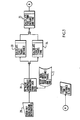
- Figure 3 of this application shows a simple flow diagram demonstrating the logic involved in the actual operation of the program.
- the trip data comprised of the desired origin and destination, is entered into the computer system by the Keyboard 20 of Figure 3. This information is used to retrieve selected information from the disk memory which contains the R.S.V.P. Data Base 1. This selection of the appropriate interzone travel distances and times is achieved using conventional, well known computer programming techniques, and is represented in Figure 3 by block 21.
- This trip information is applied to subroutines, within the computer system, which are individually programmed to compute the exact fare and exact distance utilizing the pre-programmed arithmetic equations involved in process 23 and process 24. The result of these calculation processes is then applied to the fare calculation subroutine 25, which has within it a preprogrammed arithmetic equation for determining the fare utilizing the results of calculation 23 and calculation 24.
- the exact arithmetic equation schemes programmed into each subroutine are themselves obvious to one skilled in the art.
Landscapes
- Physics & Mathematics (AREA)
- General Physics & Mathematics (AREA)
- Devices For Checking Fares Or Tickets At Control Points (AREA)
Claims (7)
Priority Applications (2)
| Application Number | Priority Date | Filing Date | Title |
|---|---|---|---|
| DE8080300185T DE3071659D1 (en) | 1980-01-19 | 1980-01-19 | Fare computation and dispatching method |
| EP19800300185 EP0032607B1 (de) | 1980-01-19 | 1980-01-19 | Fahrpreisberechnungs- und Fahrdienstleitungsverfahren |
Applications Claiming Priority (1)
| Application Number | Priority Date | Filing Date | Title |
|---|---|---|---|
| EP19800300185 EP0032607B1 (de) | 1980-01-19 | 1980-01-19 | Fahrpreisberechnungs- und Fahrdienstleitungsverfahren |
Publications (2)
| Publication Number | Publication Date |
|---|---|
| EP0032607A1 EP0032607A1 (de) | 1981-07-29 |
| EP0032607B1 true EP0032607B1 (de) | 1986-07-16 |
Family
ID=8187082
Family Applications (1)
| Application Number | Title | Priority Date | Filing Date |
|---|---|---|---|
| EP19800300185 Expired EP0032607B1 (de) | 1980-01-19 | 1980-01-19 | Fahrpreisberechnungs- und Fahrdienstleitungsverfahren |
Country Status (2)
| Country | Link |
|---|---|
| EP (1) | EP0032607B1 (de) |
| DE (1) | DE3071659D1 (de) |
Families Citing this family (7)
| Publication number | Priority date | Publication date | Assignee | Title |
|---|---|---|---|---|
| FR2542478B1 (fr) * | 1983-03-07 | 1986-10-31 | Belou Michel | Dispositif de surveillance a distance du fonctionnement des moteurs d'un ensemble de vehicules |
| GB2152261A (en) * | 1984-01-04 | 1985-07-31 | John Thomas Everitt | Taximeter remote indicator |
| FR2559929A1 (fr) * | 1984-02-20 | 1985-08-23 | Belletante Guy | Dispositif de centralisation informatisee et automatique de la maintenance des engins mobiles |
| GB8903123D0 (en) * | 1989-02-11 | 1989-03-30 | Lewis Roger W D | Vehicle monitoring system |
| EP1100064A1 (de) * | 1999-11-10 | 2001-05-16 | Bull HN Information Systems Italia S.p.A. | Managementsystem für eine Taxiflotte |
| JP2001331894A (ja) * | 2000-05-19 | 2001-11-30 | Nec Corp | 輸送サービスシステムおよび輸送サービス方法 |
| DE102022122664A1 (de) * | 2022-09-07 | 2024-03-07 | Antonios Ikonomou-Brinkmann | Echtzeitquittungsausstellungsdruckgeräteverfahren, zum Berechnen des auf einem elektronischen Taxameter aufgezeigten Preises einer Taxifahrt |
Family Cites Families (4)
| Publication number | Priority date | Publication date | Assignee | Title |
|---|---|---|---|---|
| FR1590348A (de) * | 1968-10-30 | 1970-04-13 | ||
| DE2037048B2 (de) * | 1970-07-25 | 1973-05-17 | Kienzle Apparate GmbH, 7730 Vülmgen | Taxametereinrichtung mit steuerbarer, mehrstufiger tarifumschaltung |
| CA983624A (en) * | 1972-11-03 | 1976-02-10 | Canadian Marconi Company | Dispatch system with on-line data processor |
| CA1060113A (en) * | 1974-05-13 | 1979-08-07 | Howard S. White | Monitoring system for vehicles |
-
1980
- 1980-01-19 EP EP19800300185 patent/EP0032607B1/de not_active Expired
- 1980-01-19 DE DE8080300185T patent/DE3071659D1/de not_active Expired
Also Published As
| Publication number | Publication date |
|---|---|
| DE3071659D1 (en) | 1986-08-21 |
| EP0032607A1 (de) | 1981-07-29 |
Similar Documents
| Publication | Publication Date | Title |
|---|---|---|
| US4212069A (en) | Paratransit fare computation and dispatching method | |
| EP0944229B1 (de) | System und Verfahren für Informationsübertragung über ein Telefonnetzwerk | |
| AU2004262371B2 (en) | Inspection data recording apparatus and method | |
| WO1992014215A1 (en) | Method and apparatus for providing shortest elapsed time route information to users | |
| WO2001069176A1 (en) | Method of monitoring vehicular mileage | |
| JPS62502784A (ja) | 郵便料金計量機械の予納金蓄積手段中に任意の予納額を制御して収納し、また払出すための方法と装置 | |
| KR20180122274A (ko) | 교통카드 데이터 기반 버스 정보와 승하차 누락 및 결측 데이터 보정 시스템 | |
| US4240146A (en) | Indicating devices | |
| WO2006008527A2 (en) | Improved digital tachograph system | |
| EP0032607A1 (de) | Fahrpreisberechnungs- und Fahrdienstleitungsverfahren | |
| US4570228A (en) | Apparatus in taximeters for coaction by teletransmission with a common calculator unit | |
| NZ204694A (en) | Taximeter | |
| US4685116A (en) | Incremental count display system | |
| GB2083932A (en) | Assimilating Utility Meter Data with Electronic Scanning | |
| EP1093642A1 (de) | Vorrichtung zum berechnen von fahrpreisen in fahrzeugen insbesondere in taxis, bussen oder dergleichen | |
| JP2022002062A (ja) | 駐車料金設定システム | |
| JPS6357839B2 (de) | ||
| JP2003036498A (ja) | タクシー管理システム | |
| GB2084773A (en) | Assimilating utility meter data with electronic probing | |
| JPH0226280B2 (de) | ||
| EP1796058B1 (de) | Verfahren und System zur Schätzung einer Ankunftszeit eines öffentlichen Verkehrsmittels entlang bestimmter Punkte seines Weges | |
| WO1999009524A1 (en) | Improved travel pass/ticket issuing and/or validating system | |
| JP3189941B2 (ja) | タクシー運行情報収集装置用インタフェース装置 | |
| JP3042591B2 (ja) | タクシー運行情報処理装置及びタクシー運行情報処理方法 | |
| Furth | Integration of fareboxes with other electronic devices on transit vehicles |
Legal Events
| Date | Code | Title | Description |
|---|---|---|---|
| PUAI | Public reference made under article 153(3) epc to a published international application that has entered the european phase |
Free format text: ORIGINAL CODE: 0009012 |
|
| AK | Designated contracting states |
Designated state(s): DE FR GB SE |
|
| 17P | Request for examination filed |
Effective date: 19810616 |
|
| RBV | Designated contracting states (corrected) |
Designated state(s): DE FR GB SE |
|
| GRAA | (expected) grant |
Free format text: ORIGINAL CODE: 0009210 |
|
| AK | Designated contracting states |
Kind code of ref document: B1 Designated state(s): DE FR GB SE |
|
| REF | Corresponds to: |
Ref document number: 3071659 Country of ref document: DE Date of ref document: 19860821 |
|
| ET | Fr: translation filed | ||
| PLBE | No opposition filed within time limit |
Free format text: ORIGINAL CODE: 0009261 |
|
| STAA | Information on the status of an ep patent application or granted ep patent |
Free format text: STATUS: NO OPPOSITION FILED WITHIN TIME LIMIT |
|
| 26N | No opposition filed | ||
| PGFP | Annual fee paid to national office [announced via postgrant information from national office to epo] |
Ref country code: GB Payment date: 19930118 Year of fee payment: 14 |
|
| PGFP | Annual fee paid to national office [announced via postgrant information from national office to epo] |
Ref country code: FR Payment date: 19930122 Year of fee payment: 14 |
|
| PGFP | Annual fee paid to national office [announced via postgrant information from national office to epo] |
Ref country code: SE Payment date: 19930125 Year of fee payment: 14 |
|
| PGFP | Annual fee paid to national office [announced via postgrant information from national office to epo] |
Ref country code: DE Payment date: 19930209 Year of fee payment: 14 |
|
| PG25 | Lapsed in a contracting state [announced via postgrant information from national office to epo] |
Ref country code: GB Effective date: 19940119 |
|
| PG25 | Lapsed in a contracting state [announced via postgrant information from national office to epo] |
Ref country code: SE Effective date: 19940120 |
|
| GBPC | Gb: european patent ceased through non-payment of renewal fee |
Effective date: 19940119 |
|
| PG25 | Lapsed in a contracting state [announced via postgrant information from national office to epo] |
Ref country code: FR Effective date: 19940930 |
|
| PG25 | Lapsed in a contracting state [announced via postgrant information from national office to epo] |
Ref country code: DE Effective date: 19941001 |
|
| REG | Reference to a national code |
Ref country code: FR Ref legal event code: ST |
|
| EUG | Se: european patent has lapsed |
Ref document number: 80300185.8 Effective date: 19940810 |