EP0032636A1 - Spannfeder und Klickerarm für ein Bremssystem - Google Patents
Spannfeder und Klickerarm für ein Bremssystem Download PDFInfo
- Publication number
- EP0032636A1 EP0032636A1 EP80304766A EP80304766A EP0032636A1 EP 0032636 A1 EP0032636 A1 EP 0032636A1 EP 80304766 A EP80304766 A EP 80304766A EP 80304766 A EP80304766 A EP 80304766A EP 0032636 A1 EP0032636 A1 EP 0032636A1
- Authority
- EP
- European Patent Office
- Prior art keywords
- periphery
- spool
- reel
- hub
- tab
- Prior art date
- Legal status (The legal status is an assumption and is not a legal conclusion. Google has not performed a legal analysis and makes no representation as to the accuracy of the status listed.)
- Withdrawn
Links
Images


Classifications
-
- A—HUMAN NECESSITIES
- A01—AGRICULTURE; FORESTRY; ANIMAL HUSBANDRY; HUNTING; TRAPPING; FISHING
- A01K—ANIMAL HUSBANDRY; AVICULTURE; APICULTURE; PISCICULTURE; FISHING; REARING OR BREEDING ANIMALS, NOT OTHERWISE PROVIDED FOR; NEW BREEDS OF ANIMALS
- A01K89/00—Reels
- A01K89/02—Brake devices for reels
- A01K89/027—Brake devices for reels with pick-up, i.e. for reels with the guiding member rotating and the spool not rotating during normal retrieval of the line
- A01K89/0275—Brake devices for reels with pick-up, i.e. for reels with the guiding member rotating and the spool not rotating during normal retrieval of the line with closed face
Definitions
- This invention relates to fishing reels, and more particularly, relates to a spin casting style fishing reel with a new improved drag system that incorporates a drag spring and clicker arm into one unit.
- a circular drag spring having a cantilever leaf spring that has two fulcrum points defining a first and second linear spring portion is described.
- the cantilever spring arm provides the spring force for the drag system of the reel in order for the drag system to operate.
- the drag mechanism in this reel is located at the rear of the reel and is part of a free floating drag system.
- the clicker device that is part of the drag system is operated by a separate drag cup and clicker.
- a three arm cantilever leaf spring arrangement is taught. The spring is located between the spool on the front of the reel and the spool securing nut.
- the leaf spring arms are simple single-acting springs and much less effective than the Puryear device.
- clicker spring devices indicate that the spool is revolving relative to the hub are utilized, but in each case, a separate device for making the clicking sound is required since the drag tension springs do not perform such a function.
- This invention relates to fishing reels and comprehends a very smooth operating fishing reel drag mechanism.
- the drag mechanism incorporates a clicker device that is integral with the drag spring.
- FIG. 1 generally depicts an exploded perspective view of such a reel.
- a housing 11 preferably made of a plastic material such as acrylonitrile butadiene styrene (ABS) or glass-filled polycarbonate, has a center deck plate 14 with a forward and rear body portions 15 and 16.
- a central hub 35 projects forward of the deck plate 14 with a drag plate 210, back spool washer 230, back flat drag washer 233, spool assembly 130, front flat drag washer 235, front spool washer 237, all secured to the hub 35 by means of spool retainer clip 240 which fits into a groove (not shown in Figure 1).
- a center shaft 251 is mounted in a hole (not shown in Figure 1) in hub 35 with the spinner head 242 mounted on the forward threaded end of the shaft 251 by means of nut 250.
- the spinner head 242 partially surrounds the forward flange of the spool 130 with fishing line 99 being wound thereon.
- a front cover 90 secured on the first forward body portion 15 has a front hole (not shown in Figure 1) which acts as a fishing line guide as the line is cast from the reel and rewound after casting.
- a clutch head screw 201 is mounted in the interior 21 of the second body portion 16 with clutch wheel 204 mounted on screw 201.
- Tab 217 fits into the head of screw 201 and when the clutch wheel 204 is revolved upward toward stem 12 and screw 201 advances forward toward the spool retainer clip 240 increasing the clamping force on the spool 130 so that the ability of spool 130 to revolve relative to the hub 35 is decreased.
- the center shaft 251 is slidably and rotatably mounted in bearing 269 which is mounted in the deck plate 14. Slidably mounted on center shaft 251 in the second body portion is pinion gear 260 and maintained in place by the center shaft spring 265.
- a finger brake lever 300 is mounted on the housing 11 exterior the first body portion 15 and inside the second body portion 16 and being in operable contact with the distal end 255 of the shaft 251.
- the pickup pin mechanism 243 mounted on spinner head 242 cooperates with the cam 37 mounted on the face of hub 35 to maintain the spinner head 242 in a forward position. In this forward position, the fishing line 99 can be cast from the reel 10.
- Crank assembly 310 is coupled with the anti-reverse assembly 340 which comprises a ratchet (on the back side of face gear 313 and not shown in Figure 1), an anti-reverse drag arm 317, a drag spring 329 and spacer washer 341 all mounted on the hollow crank shaft 311.
- An anti-reverse pawl 321 is mounted in the deck plate 14 and received in between the back of the face gear 313 and drag arm 317 for engageable and disengageable contact with the ratchet.
- the crank assembly 310 is mounted in bearing supports 39 and 40 by sliding between slots in the supports 39 and 40.
- Crank bearings 160 and 161 mounted in supports 39 and 40 provide suitable bearings for the hollow shaft 311.
- a crank rod 331 is slip fitted into the hole in shaft 311 and keyed thereto.
- Crank rod nut 342 is secured to the threaded end to fasten rod 331 to the reel 10.
- the rod 331 is connected to the crank handle 332 and crank knob 333.
- the gear 313 is in engageable contact with pinion 260 so that when the crank handle 332 and knob 333 are rotated in the forward direction (toward the front cover), the crank shaft 251 rotates causing the spinner head 242 to rotate as well.
- This rotative motion disengages the pickup pin mechanism 243 from the hub 35 cam 37 causing the spinner head 242 and shaft 251 to move rearward.
- This same motion causes the pickup pin of the mechanism 243 to extend outwardly beyond the spinner head 242 so that the fishing line 99 can be wound on the spool 130.
- Anti-reverse actuator 150 is mounted in upper housing hole 50 and retained therein by retainer clip 170.
- the actuator 150 is in cooperative contact with the anti-reverse drag arm 317. In one position the actuator 150 disengages the anti-reverse assembly 340 permitting the crank rod 331 and the crank assembly to rotate in either the forward direction (upward toward the stem 12) or the reverse direction (downward from the stem 12 toward the back of the reel).
- a back cover 95 is secured on the second back portion 16 to enclose the reel 10.
- Cover lock 70 is mounted within the housing 11 and is tightened in place by screw 71 clamping the covers 90 and 95 to the housing.
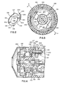
- a new and novel drag assembly for a spin casting style fishing reel utilizes a new and novel drag plate 210 which has a periphery 218 and a center hole 212 defining a body portion 213.
- the body portion 213 is bent near the center further defining first and second semi-sections 214 and 215 that are each substantially planar but are non-planar with respect to each other.
- non-planar semi-section or 'non-planar semi-circle refers to the configuration of 214 and 215 which meet at bend line 210a or bearing surface 219. This portion forms a metal disk 211 and the spring aspect of drag plate 210.
- the plate 210 has first and second tabs 216 and 217 bent approximately 90° to the plate 210 and extending in a first direction.
- Cantilever arm 220 has a proximal end 221 secured to drag plate 210 by coupling 222 and has a distal end 223 with tip 224 bent in a second direction relative to the bent tabs 216 and 217.
- the deck plate 14 has two holes 33 and 34 and a triangular section 68 with a hole 69.
- the holes 69 and 33 are coaxial.
- the clutch screw head 201 is positioned in hole 33 with threaded shank positioned in and supported by hole 69.
- Threaded clutch wheel hole 205 is received on threaded shank 203 and mounted so that part of the clutch wheel protrudes through the slot 64 on the exterior of the body portion 15.
- the drag plate 210 is positioned on hub 35, the tab 216 fits into hole 34 and tab 217 fits into slot 207 of screw 201.
- Adjacent the drag plate 210 on the hub 35 is the back spool washer 230 with hole 232 and the aligning prongs 231 that mates with slot 38 to prevent the washer from rotating.
- Adjacent the washer 230 is back drag washer 233 with hole 234 for mounting on hub 35.
- the spool 130 is mounted on hub 35 adjacent the drag washer 233 and next in line comes the front drag washer 235 followed by the front spool washer 237 with the aligning prongs to prevent the washer from rotating relative to the hub.
- Retainer clip 240 is press-fitted into groove 36; preferably, the retainer is C-shaped with three positioning prongs 241.
- the spring face 219 at the bend 210a of the drag plate 210 bears against the outer surface 135 of flange 133 by means of interaction between the washers 230 and 233.
- the slotted clutch head 202 moves forward of the deck plate 14 moving the drag plate 210 toward the retainer clip 240 tightly clamping the spool 130 between the non-rotary washers 230 and 237 and the low-friction disk washers 233 and 235.
- the washers 233 and 235 are made from a low-friction plastic material such as teflon or nylon.
- the tab 217 is forced forward. This movement in turn causes the bent line 210a or the spring bearing surface 219 to push on'the washer 230.
- the washer 230 is made of metal to help equalize pressure on the friction washer 233. This forward motion of the screw head 202 causes a tight clamping force on the spool 130 preventing its rotation relative to the hub 35.
- a further embodiment contemplated by this invention is a provision that the outer surface 138 of the spool 130 has a plurality of radial serrations 139.
- the drag plate 210 has a cantilever arm 220 that follows the contour or periphery 218 of the plate 210.
- the arm 220 projects in a second direction opposite to the tabs 216 and 217.
- the bent tip 224 contacts the serrations 139.
- the arm 220 extends outside the periphery of the washers 230 and 233.
- the drag plate 210 can be made circular as shown in the Figures 2 and 3, if desired.
- the semi-sections 214 and 215 are semi-circular in shape still maintaining the bent line 210a or primary spring surface 219. It has been further found advantageous to make the plate 210 from material such as spring quality stainless steel, spring hardened brass, spring steel (plated or unplated) and the like.
- the outer surface 138 of spool 130 can be undercut as shown as 176.
- This undercut 176 permits the drag plate 130, the washer 230 and the washer 233 to be thicker and thus able to apply a more uniform drag pressure against the spool 130.
Landscapes
- Life Sciences & Earth Sciences (AREA)
- Environmental Sciences (AREA)
- Animal Husbandry (AREA)
- Biodiversity & Conservation Biology (AREA)
Applications Claiming Priority (2)
| Application Number | Priority Date | Filing Date | Title |
|---|---|---|---|
| US11295980A | 1980-01-17 | 1980-01-17 | |
| US112959 | 1980-01-17 |
Publications (1)
| Publication Number | Publication Date |
|---|---|
| EP0032636A1 true EP0032636A1 (de) | 1981-07-29 |
Family
ID=22346797
Family Applications (1)
| Application Number | Title | Priority Date | Filing Date |
|---|---|---|---|
| EP80304766A Withdrawn EP0032636A1 (de) | 1980-01-17 | 1980-12-30 | Spannfeder und Klickerarm für ein Bremssystem |
Country Status (3)
| Country | Link |
|---|---|
| EP (1) | EP0032636A1 (de) |
| JP (1) | JPS56106542A (de) |
| CA (1) | CA1152477A (de) |
Cited By (1)
| Publication number | Priority date | Publication date | Assignee | Title |
|---|---|---|---|---|
| CN117202781A (zh) * | 2021-04-27 | 2023-12-08 | 古洛布莱株式会社 | 卷线装置、钓鱼用卷线器以及绞车 |
Families Citing this family (2)
| Publication number | Priority date | Publication date | Assignee | Title |
|---|---|---|---|---|
| JPS58152875U (ja) * | 1982-04-08 | 1983-10-13 | ダイワ精工株式会社 | 魚釣用覆面型リ−ル |
| US5427325A (en) * | 1992-12-08 | 1995-06-27 | Zebco Corporation | Drag system for spin-cast reels |
Citations (1)
| Publication number | Priority date | Publication date | Assignee | Title |
|---|---|---|---|---|
| US3297275A (en) * | 1964-07-24 | 1967-01-10 | Pflueger Corp | Crank operated drag for fishing reels |
-
1980
- 1980-12-30 EP EP80304766A patent/EP0032636A1/de not_active Withdrawn
-
1981
- 1981-01-15 CA CA000368567A patent/CA1152477A/en not_active Expired
- 1981-01-16 JP JP491781A patent/JPS56106542A/ja active Pending
Patent Citations (1)
| Publication number | Priority date | Publication date | Assignee | Title |
|---|---|---|---|---|
| US3297275A (en) * | 1964-07-24 | 1967-01-10 | Pflueger Corp | Crank operated drag for fishing reels |
Cited By (1)
| Publication number | Priority date | Publication date | Assignee | Title |
|---|---|---|---|---|
| CN117202781A (zh) * | 2021-04-27 | 2023-12-08 | 古洛布莱株式会社 | 卷线装置、钓鱼用卷线器以及绞车 |
Also Published As
| Publication number | Publication date |
|---|---|
| CA1152477A (en) | 1983-08-23 |
| JPS56106542A (en) | 1981-08-24 |
Similar Documents
| Publication | Publication Date | Title |
|---|---|---|
| US3836092A (en) | Closed face spinning reel | |
| US5556049A (en) | Anti-reverse fishing reel with drag control and replaceable spool | |
| EP2174543B1 (de) | Widerstandseinstellungsvorrichtung für Doppellagerspule | |
| US5199665A (en) | Electronic bait alert for a fishing reel | |
| US4371124A (en) | Drag system for spinning style fishing reel | |
| US6336605B1 (en) | Self positioning adjustable brake for baitcast reel | |
| US4378914A (en) | Uniform drag system for spin cast reels | |
| US5810274A (en) | Apparatus for attaching a cover to a fishing reel | |
| US4359197A (en) | Silent-selective anti-reverse mechanism | |
| US4408729A (en) | Star drag system for spin cast reels | |
| CA1145313A (en) | Rotor brake for fishing reel | |
| US3061230A (en) | Fishing reel | |
| US4474341A (en) | Uniform drag system for spin cast reels | |
| CA1152477A (en) | Drag system tension spring and clicker arm | |
| KR101403928B1 (ko) | 스피닝 릴의 드랙 손잡이 조립체 | |
| US5427325A (en) | Drag system for spin-cast reels | |
| US4193561A (en) | Clicker device for fishing reel | |
| US20040178290A1 (en) | Spinning reel sound producing mechanism | |
| CA1164840A (en) | Drag system tension spring and clicker arm | |
| US3900167A (en) | Closed face spinning reel | |
| US4522347A (en) | Drag adjustment click spring assembly | |
| US4695009A (en) | Bait alert for spin cast reel | |
| US4548367A (en) | Bait clicker for fishing reel | |
| US4523726A (en) | Anti-reverse mechanism | |
| JPH104839A (ja) | 魚釣用スピニングリール |
Legal Events
| Date | Code | Title | Description |
|---|---|---|---|
| PUAI | Public reference made under article 153(3) epc to a published international application that has entered the european phase |
Free format text: ORIGINAL CODE: 0009012 |
|
| AK | Designated contracting states |
Designated state(s): DE FR GB IT SE |
|
| 17P | Request for examination filed |
Effective date: 19811204 |
|
| STAA | Information on the status of an ep patent application or granted ep patent |
Free format text: STATUS: THE APPLICATION IS DEEMED TO BE WITHDRAWN |
|
| 18D | Application deemed to be withdrawn |
Effective date: 19830819 |
|
| RIN1 | Information on inventor provided before grant (corrected) |
Inventor name: NEUFELD, HENRY L. |