EP0032694A1 - Dispositif pour déterminer la position d'un commutateur et pour surveiller l'état de court-circuit et de coupure de la ligne correspondante - Google Patents
Dispositif pour déterminer la position d'un commutateur et pour surveiller l'état de court-circuit et de coupure de la ligne correspondante Download PDFInfo
- Publication number
- EP0032694A1 EP0032694A1 EP81100129A EP81100129A EP0032694A1 EP 0032694 A1 EP0032694 A1 EP 0032694A1 EP 81100129 A EP81100129 A EP 81100129A EP 81100129 A EP81100129 A EP 81100129A EP 0032694 A1 EP0032694 A1 EP 0032694A1
- Authority
- EP
- European Patent Office
- Prior art keywords
- switch
- zener diodes
- arrangement
- voltage
- circuit
- Prior art date
- Legal status (The legal status is an assumption and is not a legal conclusion. Google has not performed a legal analysis and makes no representation as to the accuracy of the status listed.)
- Granted
Links
Images

Classifications
-
- G—PHYSICS
- G01—MEASURING; TESTING
- G01R—MEASURING ELECTRIC VARIABLES; MEASURING MAGNETIC VARIABLES
- G01R31/00—Arrangements for testing electric properties; Arrangements for locating electric faults; Arrangements for electrical testing characterised by what is being tested not provided for elsewhere
- G01R31/50—Testing of electric apparatus, lines, cables or components for short-circuits, continuity, leakage current or incorrect line connections
-
- H—ELECTRICITY
- H01—ELECTRIC ELEMENTS
- H01H—ELECTRIC SWITCHES; RELAYS; SELECTORS; EMERGENCY PROTECTIVE DEVICES
- H01H9/00—Details of switching devices, not covered by groups H01H1/00 - H01H7/00
- H01H9/16—Indicators for switching condition, e.g. "on" or "off"
- H01H9/167—Circuits for remote indication
-
- H—ELECTRICITY
- H02—GENERATION; CONVERSION OR DISTRIBUTION OF ELECTRIC POWER
- H02J—ELECTRIC POWER NETWORKS; CIRCUIT ARRANGEMENTS OR SYSTEMS FOR SUPPLYING OR DISTRIBUTING ELECTRIC POWER; SYSTEMS FOR STORING ELECTRIC ENERGY
- H02J13/00—Circuit arrangements for providing remote monitoring or remote control of equipment in a power distribution network
- H02J13/13—Circuit arrangements for providing remote monitoring or remote control of equipment in a power distribution network characterised by the transmission of data to equipment in the power network
-
- H—ELECTRICITY
- H02—GENERATION; CONVERSION OR DISTRIBUTION OF ELECTRIC POWER
- H02J—ELECTRIC POWER NETWORKS; CIRCUIT ARRANGEMENTS OR SYSTEMS FOR SUPPLYING OR DISTRIBUTING ELECTRIC POWER; SYSTEMS FOR STORING ELECTRIC ENERGY
- H02J13/00—Circuit arrangements for providing remote monitoring or remote control of equipment in a power distribution network
- H02J13/18—Circuit arrangements for providing remote monitoring or remote control of equipment in a power distribution network characterised by the remotely-controlled equipment, e.g. converters or transformers
- H02J13/34—Circuit arrangements for providing remote monitoring or remote control of equipment in a power distribution network characterised by the remotely-controlled equipment, e.g. converters or transformers the equipment being switches, relays or circuit breakers
-
- Y—GENERAL TAGGING OF NEW TECHNOLOGICAL DEVELOPMENTS; GENERAL TAGGING OF CROSS-SECTIONAL TECHNOLOGIES SPANNING OVER SEVERAL SECTIONS OF THE IPC; TECHNICAL SUBJECTS COVERED BY FORMER USPC CROSS-REFERENCE ART COLLECTIONS [XRACs] AND DIGESTS
- Y02—TECHNOLOGIES OR APPLICATIONS FOR MITIGATION OR ADAPTATION AGAINST CLIMATE CHANGE
- Y02E—REDUCTION OF GREENHOUSE GAS [GHG] EMISSIONS, RELATED TO ENERGY GENERATION, TRANSMISSION OR DISTRIBUTION
- Y02E60/00—Enabling technologies; Technologies with a potential or indirect contribution to GHG emissions mitigation
-
- Y—GENERAL TAGGING OF NEW TECHNOLOGICAL DEVELOPMENTS; GENERAL TAGGING OF CROSS-SECTIONAL TECHNOLOGIES SPANNING OVER SEVERAL SECTIONS OF THE IPC; TECHNICAL SUBJECTS COVERED BY FORMER USPC CROSS-REFERENCE ART COLLECTIONS [XRACs] AND DIGESTS
- Y04—INFORMATION OR COMMUNICATION TECHNOLOGIES HAVING AN IMPACT ON OTHER TECHNOLOGY AREAS
- Y04S—SYSTEMS INTEGRATING TECHNOLOGIES RELATED TO POWER NETWORK OPERATION, COMMUNICATION OR INFORMATION TECHNOLOGIES FOR IMPROVING THE ELECTRICAL POWER GENERATION, TRANSMISSION, DISTRIBUTION, MANAGEMENT OR USAGE, i.e. SMART GRIDS
- Y04S10/00—Systems supporting electrical power generation, transmission or distribution
- Y04S10/18—Systems supporting electrical power generation, transmission or distribution using switches, relays or circuit breakers, e.g. intelligent electronic devices [IED]
-
- Y—GENERAL TAGGING OF NEW TECHNOLOGICAL DEVELOPMENTS; GENERAL TAGGING OF CROSS-SECTIONAL TECHNOLOGIES SPANNING OVER SEVERAL SECTIONS OF THE IPC; TECHNICAL SUBJECTS COVERED BY FORMER USPC CROSS-REFERENCE ART COLLECTIONS [XRACs] AND DIGESTS
- Y04—INFORMATION OR COMMUNICATION TECHNOLOGIES HAVING AN IMPACT ON OTHER TECHNOLOGY AREAS
- Y04S—SYSTEMS INTEGRATING TECHNOLOGIES RELATED TO POWER NETWORK OPERATION, COMMUNICATION OR INFORMATION TECHNOLOGIES FOR IMPROVING THE ELECTRICAL POWER GENERATION, TRANSMISSION, DISTRIBUTION, MANAGEMENT OR USAGE, i.e. SMART GRIDS
- Y04S40/00—Systems for electrical power generation, transmission, distribution or end-user application management characterised by the use of communication or information technologies, or communication or information technology specific aspects supporting them
- Y04S40/12—Systems for electrical power generation, transmission, distribution or end-user application management characterised by the use of communication or information technologies, or communication or information technology specific aspects supporting them characterised by data transport means between the monitoring, controlling or managing units and monitored, controlled or operated electrical equipment
Definitions
- the invention relates to an arrangement for determining the switch position of a switch and for monitoring the two-wire line connected to the switch for short-circuit and interruption, with an evaluation arrangement which contains a generator for generating a test voltage or a test current with periodically changing amplitude and which at least one each provides the switching position and a signal indicating a fault.
- the use of a changeover contact as a switch often means additional effort, since auxiliary switches on switching devices and relays provided for reporting purposes are usually designed as normally closed or normally open contacts.
- the invention has for its object to provide an arrangement which enables the switching position of a normally open or normally closed contact as well as a short circuit or a line break to be displayed with simple means.
- the series circuit comprising the make contact 3a or the break contact 3b and the Zener diode 4 can also be bridged by a Zener diode 6.
- the threshold voltage of the Zener diode 6 should be chosen higher than that of the Zener diode 4, for example twice as high. The same applies to the case that a changeover switch 3c is used as the switch (FIG. 3).
- a trigger circuit 8 is connected to a resistor 7 arranged in the course of line 2.
- the output signal of the trigger circuit assumes the course shown in FIGS. 4b and 4c depending on the switch position of the switch or the state of the line. The dependent on the course of switching positions are located from the position shown in Figure 4a, geannon- from the generator 1 t s test voltage and the threshold voltages u u + z4 z5 of the Zener diodes. If, according to FIG. 4, the threshold voltage of the Zener diode 6 is chosen twice as large as that of the Zener diode 4, it corresponds to the sum of the Zener voltages u z4 + u zS .
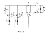
- FIG. 5 shows a further exemplary embodiment of the invention, which differs from the embodiment according to FIG. 1 by two additional trigger circuits 9, 12.
- the trigger circuit 9 is connected to a resistor 10 and, together with a zener diode 11, forms a series circuit connected to the test voltage.
- a series circuit is formed from a zener diode 14 and a resistor 13 to which the trigger circuit 12 is connected.
- the threshold voltage of the Zener diode 11 corresponds, for example, to the threshold voltage of the Zener diode 4 and the threshold voltage of the Zener diode 14 corresponds, for example, to the threshold voltage of the Zener diode 6 or the sum of the threshold voltages of the Zener diodes 4 and 5.
- test voltage runs only in the positive range. If the test voltage also has a negative component, this can be evaluated for feedback purposes.
Landscapes
- Engineering & Computer Science (AREA)
- Power Engineering (AREA)
- Physics & Mathematics (AREA)
- General Physics & Mathematics (AREA)
- Testing Of Short-Circuits, Discontinuities, Leakage, Or Incorrect Line Connections (AREA)
Applications Claiming Priority (2)
| Application Number | Priority Date | Filing Date | Title |
|---|---|---|---|
| DE3001940A DE3001940C2 (de) | 1980-01-21 | 1980-01-21 | Anordnung zur Ermittlung der Schaltstellung eines Schalters und zur Überwachung der zugehörigen Leitung auf Kurzschluß und Unterbrechung |
| DE3001940 | 1980-01-21 |
Publications (2)
| Publication Number | Publication Date |
|---|---|
| EP0032694A1 true EP0032694A1 (fr) | 1981-07-29 |
| EP0032694B1 EP0032694B1 (fr) | 1984-05-09 |
Family
ID=6092511
Family Applications (1)
| Application Number | Title | Priority Date | Filing Date |
|---|---|---|---|
| EP81100129A Expired EP0032694B1 (fr) | 1980-01-21 | 1981-01-09 | Dispositif pour déterminer la position d'un commutateur et pour surveiller l'état de court-circuit et de coupure de la ligne correspondante |
Country Status (5)
| Country | Link |
|---|---|
| US (1) | US4398144A (fr) |
| EP (1) | EP0032694B1 (fr) |
| AU (1) | AU6632981A (fr) |
| DE (2) | DE3001940C2 (fr) |
| ZA (1) | ZA81370B (fr) |
Cited By (6)
| Publication number | Priority date | Publication date | Assignee | Title |
|---|---|---|---|---|
| FR2536903A1 (fr) * | 1982-11-29 | 1984-06-01 | Commissariat Energie Atomique | Dispositif de controle de l'etat d'un commutateur |
| EP0249410A1 (fr) * | 1986-06-11 | 1987-12-16 | VOLEX GROUP plc | Commutateur electrique commandé à main pour l'utilisation dans systèmes de traitement et de controle d'informations. |
| DE3724926A1 (de) * | 1987-07-28 | 1989-02-09 | Bayerische Motoren Werke Ag | Schaltungsanordnung zur ueberpruefung der zuleitungen eines schalters oder sensors |
| AU584540B2 (en) * | 1987-04-06 | 1989-05-25 | Toshiba, Kabushiki Kaisha | Circuit for detecting on/off states of switches |
| EP0327403A3 (fr) * | 1988-02-05 | 1990-12-05 | LUCAS INDUSTRIES public limited company | Système de contrôle de condition |
| DE10120238A1 (de) * | 2001-04-19 | 2002-12-05 | Heidenhain Gmbh Dr Johannes | Betätigungseinrichtung |
Families Citing this family (11)
| Publication number | Priority date | Publication date | Assignee | Title |
|---|---|---|---|---|
| US4647920A (en) * | 1983-09-09 | 1987-03-03 | Corso Philip P | Fault detector |
| US4845475A (en) * | 1987-11-17 | 1989-07-04 | The Boeing Company | Automatic testing of position sensing devices employing stored sensed position |
| US4864285A (en) * | 1988-05-11 | 1989-09-05 | O G & E | Method and apparatus for testing contacts to determine if opened or closed |
| US5029188A (en) * | 1989-11-03 | 1991-07-02 | Joyner Engineers And Trainers | Apparatus for monitoring operation cycles of an electrically actuated device |
| CH682608A5 (de) * | 1991-10-28 | 1993-10-15 | Landis & Gyr Business Support | Anordnung zur Ueberwachung von Wechselstromschaltern. |
| DE4205079C2 (de) * | 1992-02-20 | 1995-12-07 | Licentia Gmbh | Schaltungsanordnung zur optischen Anzeige der Störung eines in zwei voneinander verschiedenen Endlagen Meldeschalter betätigenden mechanisch beweglichen Teils |
| DE4318189A1 (de) * | 1993-06-01 | 1994-12-08 | Abb Management Ag | Vorrichtung und Verfahren zur Überwachung einer Schalterstellung |
| DE4408631C2 (de) * | 1994-03-09 | 1996-11-14 | Siemens Ag | Einrichtung zur Funktionssicherheitsüberwachung von Leistungsschalteinrichtungen (Diagnosegerät) |
| US5648722A (en) * | 1995-07-28 | 1997-07-15 | Gas Research Institute | Apparatus and method for determining the state of an electrical switch within an HVAC system |
| DE19709616A1 (de) * | 1997-03-08 | 1998-09-24 | Grundig Ag | Abnehmbares Bedienteil mit einem Inkrementgeber |
| DE102009034364B4 (de) * | 2009-07-20 | 2024-01-04 | Siemens Aktiengesellschaft | Einrichtung zur Ermittlung und Bewertung von analogen zeitabhängigen elektrischen Messsignalen |
Citations (1)
| Publication number | Priority date | Publication date | Assignee | Title |
|---|---|---|---|---|
| DE2144537A1 (de) * | 1971-09-06 | 1973-03-15 | Siemens Ag | Meldeanlage |
Family Cites Families (6)
| Publication number | Priority date | Publication date | Assignee | Title |
|---|---|---|---|---|
| GB801276A (en) | 1955-02-03 | 1958-09-10 | British Thomson Houston Co Ltd | Improvements in circuit arrangements for detecting or indicating the opening of an electric switch |
| DE2542996B1 (de) * | 1975-09-26 | 1976-07-08 | Siemens Ag | Anordnung zur UEberwachung eines Meldeschalters in eigensicheren Anlagen und der zugehoerigen Zufuehrungsleitung |
| DE2641079C3 (de) * | 1976-09-11 | 1986-07-31 | Telefunken Fernseh Und Rundfunk Gmbh, 3000 Hannover | Lautsprecherschaltung |
| DE2703560C2 (de) * | 1977-01-28 | 1984-05-17 | Preussag Ag Feuerschutz, 2060 Bad Oldesloe | Schaltungsanordnung zur Überwachung des Steuerstromkreises eines über eine Zuleitung mit Gleichstrom zu speisenden Verbrauchers |
| DE2729480A1 (de) * | 1977-06-30 | 1979-01-11 | Kloeckner Humboldt Deutz Ag | Verfahren und vorrichtung zur ueberwachung und/oder erweiterung von schaltanlagen |
| US4340852A (en) * | 1979-08-09 | 1982-07-20 | Togneri Mauro G | Scanning system using alternating current for indicating the open, closed and ground condition of a contact |
-
1980
- 1980-01-21 DE DE3001940A patent/DE3001940C2/de not_active Expired
-
1981
- 1981-01-09 DE DE8181100129T patent/DE3163426D1/de not_active Expired
- 1981-01-09 EP EP81100129A patent/EP0032694B1/fr not_active Expired
- 1981-01-19 US US06/225,972 patent/US4398144A/en not_active Expired - Fee Related
- 1981-01-20 ZA ZA00810370A patent/ZA81370B/xx unknown
- 1981-01-20 AU AU66329/81A patent/AU6632981A/en not_active Abandoned
Patent Citations (1)
| Publication number | Priority date | Publication date | Assignee | Title |
|---|---|---|---|---|
| DE2144537A1 (de) * | 1971-09-06 | 1973-03-15 | Siemens Ag | Meldeanlage |
Non-Patent Citations (1)
| Title |
|---|
| TECHNICAL DIGEST - WESTERN ELECTRIC, Nr. 43, Juli 1976, Seite 7 New York, U.S.A. F.W. BECKMAN: "Diode test circuit" * Seite 7, Zenerdiode 17 * * |
Cited By (9)
| Publication number | Priority date | Publication date | Assignee | Title |
|---|---|---|---|---|
| FR2536903A1 (fr) * | 1982-11-29 | 1984-06-01 | Commissariat Energie Atomique | Dispositif de controle de l'etat d'un commutateur |
| EP0249410A1 (fr) * | 1986-06-11 | 1987-12-16 | VOLEX GROUP plc | Commutateur electrique commandé à main pour l'utilisation dans systèmes de traitement et de controle d'informations. |
| AU584540B2 (en) * | 1987-04-06 | 1989-05-25 | Toshiba, Kabushiki Kaisha | Circuit for detecting on/off states of switches |
| DE3724926A1 (de) * | 1987-07-28 | 1989-02-09 | Bayerische Motoren Werke Ag | Schaltungsanordnung zur ueberpruefung der zuleitungen eines schalters oder sensors |
| US4862091A (en) * | 1987-07-28 | 1989-08-29 | Bayerische Motoren Werke Ag | Circuit arrangement for testing the connecting lines of a switch or sensor |
| EP0301442A3 (en) * | 1987-07-28 | 1990-11-07 | Bayerische Motoren Werke Ag | Circuit for checking the leads to a switch or a sensor |
| EP0327403A3 (fr) * | 1988-02-05 | 1990-12-05 | LUCAS INDUSTRIES public limited company | Système de contrôle de condition |
| DE10120238A1 (de) * | 2001-04-19 | 2002-12-05 | Heidenhain Gmbh Dr Johannes | Betätigungseinrichtung |
| DE10120238B4 (de) * | 2001-04-19 | 2006-07-06 | Dr. Johannes Heidenhain Gmbh | Betätigungseinrichtung |
Also Published As
| Publication number | Publication date |
|---|---|
| DE3001940A1 (de) | 1981-08-06 |
| EP0032694B1 (fr) | 1984-05-09 |
| DE3001940C2 (de) | 1983-01-27 |
| DE3163426D1 (en) | 1984-06-14 |
| US4398144A (en) | 1983-08-09 |
| AU6632981A (en) | 1981-07-30 |
| ZA81370B (en) | 1982-02-24 |
Similar Documents
| Publication | Publication Date | Title |
|---|---|---|
| EP0032694A1 (fr) | Dispositif pour déterminer la position d'un commutateur et pour surveiller l'état de court-circuit et de coupure de la ligne correspondante | |
| DE2442066C3 (fr) | ||
| DE69811950T2 (de) | Elektronische überwachungsschaltung für elektrische spannung | |
| EP0269648B1 (fr) | Circuit pour au moins un comsommateur electrique d'un vehicule a moteur | |
| DE2809596C2 (fr) | ||
| EP0160235B1 (fr) | Dispositif de surveillance pour le circuit de déclenchement d'un interrupteur à puissance et procédé de surveillance | |
| DE2842966C2 (de) | Schaltung zur Überwachung der Steuerausgänge einer weiteren Schaltung | |
| DE9006605U1 (de) | Stromkreisüberwachung an bewegbaren Schließkanten | |
| EP0417392A1 (fr) | Circuit de sortie d'un potentiomètre | |
| DE1271778B (de) | Elektronische Schaltungsanordnung zum Nachweis von Stoerungen von Verstaerkern und Umschaltanordnung auf gleichartige Ersatzgeraete | |
| DE3246385A1 (de) | Schaltung zur ueberwachung der schaltfunktion von halbleiterschaltern | |
| EP0125404A1 (fr) | Circuit d'indication d'un défaut d'une charge connectée par un disjoncteur contrôlé | |
| DE2526346C3 (de) | Schaltungsanordnung zur Spannungsüberwachung für mehrere Gleichspannungen | |
| EP0030006B1 (fr) | Dispositif de circuit de téléalimentation de stations intermédiaires d'une installation de télécommunications avec surveillance de la tension de sortie d'au moins une unité d'alimentation | |
| DE1144766B (de) | Schwellwertschalter | |
| DD146782A3 (de) | Schaltungsanordnung zur staendigen ueberwachung von heizelementen | |
| DE3909613A1 (de) | Schaltungsanordnung zur selbstueberwachung eines schaltgeraetes fuer einen lastkreis | |
| DE573040C (de) | Stellvorrichtung fuer Weichen, Signale o dgl. | |
| DE3041475C2 (de) | Schaltungsanordnung zur Fernüberwachung eines Umschaltkontaktes und der daran angeschlossenen Signalleitungen | |
| DD270796B5 (de) | Schaltungsanordnung zur elektronischen sicherungsueberwachung | |
| DE3330869A1 (de) | Schaltung zum erkennen von erdschluessen in den speisekreisen von drehstrom-weichenantrieben | |
| EP0026356A1 (fr) | Circuit, en particulier pour les disjoncteurs multipolaires de courant de fuite | |
| EP0404143A1 (fr) | Circuit pour surveiller des charges à courant alternatif dans des installations de chemin de fer | |
| DE2438257B1 (de) | Schaltungsanordnung zur überwachung eines binären Signalgebers | |
| EP0656639B1 (fr) | Entrée numérique pour station de détection |
Legal Events
| Date | Code | Title | Description |
|---|---|---|---|
| PUAI | Public reference made under article 153(3) epc to a published international application that has entered the european phase |
Free format text: ORIGINAL CODE: 0009012 |
|
| AK | Designated contracting states |
Designated state(s): BE CH DE GB |
|
| 17P | Request for examination filed |
Effective date: 19810904 |
|
| GRAA | (expected) grant |
Free format text: ORIGINAL CODE: 0009210 |
|
| AK | Designated contracting states |
Designated state(s): BE CH DE GB LI |
|
| REF | Corresponds to: |
Ref document number: 3163426 Country of ref document: DE Date of ref document: 19840614 |
|
| PLBE | No opposition filed within time limit |
Free format text: ORIGINAL CODE: 0009261 |
|
| STAA | Information on the status of an ep patent application or granted ep patent |
Free format text: STATUS: NO OPPOSITION FILED WITHIN TIME LIMIT |
|
| PGFP | Annual fee paid to national office [announced via postgrant information from national office to epo] |
Ref country code: DE Payment date: 19850328 Year of fee payment: 5 |
|
| 26N | No opposition filed | ||
| REG | Reference to a national code |
Ref country code: GB Ref legal event code: 732 |
|
| PG25 | Lapsed in a contracting state [announced via postgrant information from national office to epo] |
Ref country code: GB Effective date: 19890109 |
|
| PG25 | Lapsed in a contracting state [announced via postgrant information from national office to epo] |
Ref country code: LI Effective date: 19890131 Ref country code: CH Effective date: 19890131 Ref country code: BE Effective date: 19890131 |
|
| BERE | Be: lapsed |
Owner name: SIEMENS A.G. BERLIN UND MUNCHEN Effective date: 19890131 |
|
| GBPC | Gb: european patent ceased through non-payment of renewal fee | ||
| REG | Reference to a national code |
Ref country code: CH Ref legal event code: PL |
|
| PG25 | Lapsed in a contracting state [announced via postgrant information from national office to epo] |
Ref country code: DE Effective date: 19891003 |