EP0032798A2 - Fluidbett-Verbrennungsvorrichtung und Verfahren zur Herstellung eines sich nicht zusammenballenden, mit Vanadium überzogenen Partikels - Google Patents
Fluidbett-Verbrennungsvorrichtung und Verfahren zur Herstellung eines sich nicht zusammenballenden, mit Vanadium überzogenen Partikels Download PDFInfo
- Publication number
- EP0032798A2 EP0032798A2 EP81300110A EP81300110A EP0032798A2 EP 0032798 A2 EP0032798 A2 EP 0032798A2 EP 81300110 A EP81300110 A EP 81300110A EP 81300110 A EP81300110 A EP 81300110A EP 0032798 A2 EP0032798 A2 EP 0032798A2
- Authority
- EP
- European Patent Office
- Prior art keywords
- tile
- vanadium
- plate
- tiles
- tubes
- Prior art date
- Legal status (The legal status is an assumption and is not a legal conclusion. Google has not performed a legal analysis and makes no representation as to the accuracy of the status listed.)
- Withdrawn
Links
Images

Classifications
-
- B—PERFORMING OPERATIONS; TRANSPORTING
- B01—PHYSICAL OR CHEMICAL PROCESSES OR APPARATUS IN GENERAL
- B01J—CHEMICAL OR PHYSICAL PROCESSES, e.g. CATALYSIS OR COLLOID CHEMISTRY; THEIR RELEVANT APPARATUS
- B01J8/00—Chemical or physical processes in general, conducted in the presence of fluids and solid particles; Apparatus for such processes
- B01J8/18—Chemical or physical processes in general, conducted in the presence of fluids and solid particles; Apparatus for such processes with fluidised particles
- B01J8/24—Chemical or physical processes in general, conducted in the presence of fluids and solid particles; Apparatus for such processes with fluidised particles according to "fluidised-bed" technique
-
- F—MECHANICAL ENGINEERING; LIGHTING; HEATING; WEAPONS; BLASTING
- F22—STEAM GENERATION
- F22B—METHODS OF STEAM GENERATION; STEAM BOILERS
- F22B31/00—Modifications of boiler construction, or of tube systems, dependent on installation of combustion apparatus; Arrangements or dispositions of combustion apparatus
- F22B31/0007—Modifications of boiler construction, or of tube systems, dependent on installation of combustion apparatus; Arrangements or dispositions of combustion apparatus with combustion in a fluidized bed
- F22B31/0015—Modifications of boiler construction, or of tube systems, dependent on installation of combustion apparatus; Arrangements or dispositions of combustion apparatus with combustion in a fluidized bed for boilers of the water tube type
- F22B31/0023—Modifications of boiler construction, or of tube systems, dependent on installation of combustion apparatus; Arrangements or dispositions of combustion apparatus with combustion in a fluidized bed for boilers of the water tube type with tubes in the bed
-
- F—MECHANICAL ENGINEERING; LIGHTING; HEATING; WEAPONS; BLASTING
- F23—COMBUSTION APPARATUS; COMBUSTION PROCESSES
- F23C—METHODS OR APPARATUS FOR COMBUSTION USING FLUID FUEL OR SOLID FUEL SUSPENDED IN A CARRIER GAS OR AIR
- F23C10/00—Fluidised bed combustion apparatus
- F23C10/18—Details; Accessories
- F23C10/20—Inlets for fluidisation air, e.g. grids; Bottoms
-
- B—PERFORMING OPERATIONS; TRANSPORTING
- B01—PHYSICAL OR CHEMICAL PROCESSES OR APPARATUS IN GENERAL
- B01J—CHEMICAL OR PHYSICAL PROCESSES, e.g. CATALYSIS OR COLLOID CHEMISTRY; THEIR RELEVANT APPARATUS
- B01J2208/00—Processes carried out in the presence of solid particles; Reactors therefor
- B01J2208/00008—Controlling the process
- B01J2208/00017—Controlling the temperature
- B01J2208/00106—Controlling the temperature by indirect heat exchange
- B01J2208/00115—Controlling the temperature by indirect heat exchange with heat exchange elements inside the bed of solid particles
- B01J2208/00132—Tubes
-
- Y—GENERAL TAGGING OF NEW TECHNOLOGICAL DEVELOPMENTS; GENERAL TAGGING OF CROSS-SECTIONAL TECHNOLOGIES SPANNING OVER SEVERAL SECTIONS OF THE IPC; TECHNICAL SUBJECTS COVERED BY FORMER USPC CROSS-REFERENCE ART COLLECTIONS [XRACs] AND DIGESTS
- Y10—TECHNICAL SUBJECTS COVERED BY FORMER USPC
- Y10T—TECHNICAL SUBJECTS COVERED BY FORMER US CLASSIFICATION
- Y10T428/00—Stock material or miscellaneous articles
- Y10T428/29—Coated or structually defined flake, particle, cell, strand, strand portion, rod, filament, macroscopic fiber or mass thereof
- Y10T428/2982—Particulate matter [e.g., sphere, flake, etc.]
- Y10T428/2991—Coated
-
- Y—GENERAL TAGGING OF NEW TECHNOLOGICAL DEVELOPMENTS; GENERAL TAGGING OF CROSS-SECTIONAL TECHNOLOGIES SPANNING OVER SEVERAL SECTIONS OF THE IPC; TECHNICAL SUBJECTS COVERED BY FORMER USPC CROSS-REFERENCE ART COLLECTIONS [XRACs] AND DIGESTS
- Y10—TECHNICAL SUBJECTS COVERED BY FORMER USPC
- Y10T—TECHNICAL SUBJECTS COVERED BY FORMER US CLASSIFICATION
- Y10T428/00—Stock material or miscellaneous articles
- Y10T428/29—Coated or structually defined flake, particle, cell, strand, strand portion, rod, filament, macroscopic fiber or mass thereof
- Y10T428/2982—Particulate matter [e.g., sphere, flake, etc.]
- Y10T428/2991—Coated
- Y10T428/2993—Silicic or refractory material containing [e.g., tungsten oxide, glass, cement, etc.]
Definitions
- Fluid-bed solid fuel combustors offer certain advantages over conventional boilers. Heat transfer conditions are poor in such conventional boilers due to the excessive volume flow of gas which removes too much heat. Temperature conditions within the combustion chamber vary substantially, and this leads to regions of high corrosion.
- the fluidized bed combustor overcomes many of these problems.
- hot inert solid particles e.g. ash or sand
- heat is supplied to the fuel particles to raise them to combustion temperature.
- Adequate combustion oxygen is supplied through nozzles in the bed but the overall ratio of air volume to bed volume is relatively low - e.g. 1:160 as opposed to 1:40,000 for conventional boilers.
- the high heat capacity of the inert material combined with the fluid or highly agitated nature of the bed, prevents the burning fuel from reaching excessive temperatures and helps maintain uniform temperatures throughout the bed.
- the hot inert material is, of course, an efficient means by which to transfer heat to the heat extraction tubes which pass through the bed.
- vanadium based slags The high temperature corrosion of boilers burning fuels containing vanadium is preceded by the formation of vanadium based slags on the interior of the boiler.
- a method of minimizing the formation of the vanadium based slags is to operate at combustion conditions that maximize the production of trivalent and tetravalent oxides of vanadium which have melting points of about 3,600°F which is considerably higher than the combustion temperatures obtained in these boilers.
- Vanadium oxides that are in the higher oxidation state e.g. pentavalent and septavalent oxides of vanadium and complexes thereof have melting points from about 1,200° to about 1,3000°F.
- the method employed by the prior art to minimize corrosion was to reduce the amount of air in the combustion process and thereby minimize the formation of the pentavalent and septavalent low melting oxides of vanadium while maximizing the high melting trivalent and tetravalent oxides of vanadium.
- the prior art method of reducing the air/fuel ratio did not substantially eliminate vanadium corrosion.
- the applicant has invented a fluid combustor having substantially vertical heat extraction tubes which pass through a horizontal distributor plate which supports the fluid bed. Heat transfer rates are improved in that vertically oriented tubes offer less interference to the flow of the bed particles than prior art horizontal tubes. It has also been discovered that tube wear or erosion is substantially lessened.
- the tubes according to the present invention pass through the distributor plate vertically or substantially so at points located over substantially the entire distributor plate surface and hence extract heat in a substantially uniform manner from the entire fluid bed.
- the present invention also makes it possible to take advantage of the natural water circulation effect normally attainable in a vertically oriented system.
- the water heated in the heat extraction tubes being less dense than cooler water returning from the condensor, naturally rises in the tubes toward the steam generating apparatus while the cooler water from which steam has been extracted falls to a drum located beneath the distributor plate to rise again through the heat extractor tubes.
- This natural circulation is not only highly efficient but it substantially eliminates the need for expensive pumps and the like.
- the distributor plate of the present invention is constructed of a plurality of tiles having scalloped edges, which partially extend around the tubes. Scallops on opposing plates are arranged to completely envelop a tube. These tiles allow for the easy assembly and repair or replacement of the tubes in the boiler array.
- the fluid bed combustor in another aspect of the invention has demonstrated the capability of absorbing sodium, vanadium, sulfur and potassium in the bed material. This capability minimizes corrosion or fouling especially when residual fuels are burned such as petroleum coke or other fuels high in vanadium.
- the present invention obviates the difficulties encountered in the prior art burning of fuels containing vanadium by removing the vanadium as a coating on a particulate substrate such as silica.
- the coating is preferably formed during combustion on a substrate suspended as a fluidized bed and in the presence of an oxidizing gas used to support the bed.
- the process has the dual advantage of producing a particle that does not agglomerate and further results in the substantially complete capture of the vanadium thereby preventing it from plating out on any of the boiler parts.
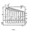
- FIG. 1 there is shown a schematic side view of a fluid bed combustor 11 having a horizontally oriented distributor plate 12.
- the distributor plate which will be described in greater detail below, separates the interior of the combustor into a lower plenum 13 and an upper combustion zone 14.
- nozzles 15 are substantially uniformly spaced over the plate surface and, as the plenum is pressurized with combustion gas, e.g. air, from source 16 the combustion gas is injected through the nozzles into the combustion zone 14.
- combustion gas e.g. air
- fluidized a term well understood in fluid bed combustor art, it is meant that the agitated bed demonstrates properties of flow, buoyancy, etc. much like those of a fluid.
- the bed has mixed therein the fuel to be burned, e.g. coal, petroleum coke or the like.
- the fuel is supplied to the bed by means readily apparent to one skilled in the art and such means, as well as known means for removing ash, are not discussed here or shown in the schematic of Fig. 1.
- heat extractor tubes 18, containing a vapor-generating fluid such as water are provided. These tubes pass upwardly through the distributor plate and through the bed 17. In order to thus pass through the plate and bed, the tubes are substantially vertically oriented, at least in the vicinity of the plate. It will of course be apparent to one skilled in the art that the vertical orientation of the heat extractor tubes can be varied significantly - the term "vertical" being used herein to mean a direction which permits tubes to easily pass upwardly from the plenum through the distributor plate and into the combustion zone. This is to be contrasted with conventional fluid bed combustors wherein the heat extractor tubes do not pass through the distributor plate (except perhaps at a conventional waterwall) and hence must assume at least a partially horizontal orientation within the bed.
- the tubes may be bent or turned to accomodate the structure and function of the particular combustor.
- the tubes are eventually directed to a drum 19 and beyond for purposes of extracting energy in the form of steam.
- Fig. 1 shows only a single set of heat extractor tubes, there may also be employed additional sets of tubes, which may or may not pass through the distributor plate, for purposes of preheating, superheating, etc. It is, nonetheless, an important feature of the invention that at least a substantial number of heat extractor tubes pass vertically through the distributor plate.
- the plate is comprised of a number of segments or tiles. These tiles have holes 22 drilled or otherwise provided therein on top of which are attached nozzles 15. The nozzles communicate with the plenum and air is injected through the nozzles both to fluidize the bed and to provide combustion air.
- each tile is scalloped by indentations 24 which, when aligned with corresponding indentations in an adjoining tile, form holes in the plate through which the tubes 18 pass.
- the tubes 18 are located substantially uniformly over the entire distributor plate surface and hence are capable of extracting heat from virtually the entire fluid bed volume.
- the individual tiles may be supported in any convenient manner such as at the ends thereof and/or by welds or projections on the tubes 18.
- the plate In order to construct the plate, one simply starts at one end of the combustor and lays in a tile. A row of heat extractor tubes is then erected followed by the laying in of the next tile.
- the tiles are attached to adjoining tiles by bolting, welding or any other suitable means.
- the tiles In the embodiment depicted in Figs. 2 and 3, the tiles have flanges 25 through which bolts 26 are passed in order to lock adjacent tiles together.
- one or more expansion joints be provided in the distributor plate.
- this joint is accomplished by leaving a gap between two adjacent tiles 27, 28 and bridging this gap with an H-channel 29.
- the H-channel 29 may be slightly larger than necessary to accommodate the tiles since this will facilitate the movement of the tiles in the H-channel.
- the H-channel does not permit significant leakage of particles from the fluid bed into the plenum since the H-channel is forced upwardly against the plate when the bed is fluidized (i.e. by the pressure in the plenum) and downwardly against the plate when the bed is slumped (i.e. by the weight of the bed).
- the H-channel may be supported in any convenient manner - e.g. at the ends.
- Fig. 2 it will also be noted from Fig. 2 that all of the tiles need not be identical.
- tile 27 immediately adjacent the expansion joint has no nozzles while tile 28 does have nozzles.
- the important consideration here is that the nozzles 15 and the tubes 18 be spread over the distributor plate surface sufficiently so that substantially the entire bed is fluidized and heat is efficiently extracted from substantially the entire fluid bed volume.
- an expansion gap may similarly be provided around the periphery of the distributor plate.
- a split channel may be provided as in Fig. 3.
- This split channel is comprised of a strip-portion 31 which is attached (e.g. welded) to one tile 32.
- a T-portion 33 of the split channel is then laid into the space between the tiles and also attached to tile 32 by a screw 34 or the like.
- the split channel may be supported in the combustor in any suitable manner.
- the bed 17 is fluidized by the injection of air into the bed through the nozzles 15.
- an oil-fired burner 20 or other known means is used to heat the bed.
- solid fuel in the form of 3/4 inch or smaller chunks is introduced into the bed.
- a sufficiently high temperature e.g. 1350°F
- combustion in the bed will become self- supporting and the oil burners are then shut down.
- the bed stabilizes at a temperature (e.g. about 1575°F) below which the bed particles, including ash, tend to slag.
- the degree of bed fluidizing may be varied in a continuous or infinite manner between the two extremes of fully slumped and fully fluidized. As the bed is partially slumped, it is possible to reduce the power output of the combustor gradually over a relatively wide range.
- Another advantage offered by the present invention is that it may be easily incorporated into or converted from a conventional oil fired combustor.
- the former combustion chamber is converted into a two- chamber system comprising a plenum beneath the tile distributor plate and a fluid bed combustion zone above.
- This ability to convert an oil fired combustor to a fluid bed solid fuel (e.g. coal) combustor is of course of particular importance in view of the increasing cost of oil as compared to more plentiful solid fuels.
- the present invention has been reduced to practice and used successfully in the form of a 1.5 million BTU/hr.
- combustor employing both ferritic-and austenitic heat extractor tubes. This combustor has been operated at a variety of temperatures with different fuels and bed materials. It is contemplated that combustors substantially smaller or larger could also be successfully operated.
- Apparatus such as that of Fig. 1 was used for conducting several tests using a high purity silica sand bed (12-30 mesh A.S.M.E.ll) and petroleum coke or a coke sometimes referred to in the art as a delayed coke having a vanadium content of approximately 450 PPM.
- the combustor or firebox conditions were controlled to produce bed temperatures between 1,500° and 1,600°F, superficial velocities between about 7.5 feet/second to about 10 feet/second and excess air levels between 12 and 50%.
- Combustion efficiencies measured during the test program ranged between 70 and 90%.
- a solids recycle system is employed comprising a cyclone separator known in the art and a recycle rate was estimated to be between 1,000 and 1,500 PPH.
- the solids recycle stream consists substantially of bed fines and unburned fuel. Materials not recycled were captured in a bag-house which is also known in the art. The elutriation of bed fines was estimated to be about 2% per hour.
- the combustor is an atmospheric fluidized bed, refractory lined to an active fluidizing area of 2.25 square feet.
- the mild steel shell comprising the outer wall is protected by a three inch lining of high duty fireclay brick and two inches of block insulation.
- the combustor is operated with a bed depth of 30-40 inches which allows for a freeboard height of approximately 6 to about 7 feet.
- a black material is produced that is collected in the baghouse along with fine particles of quartz having the same coating material on it as the quartz material in the bed i.e. a crystalline compound of vanadium, sulfur, iron calcium and aluminum with other minor elements in the crystal structure.
- the black material found in the baghouse is a grainy, opaque material containing a considerable amount of a glassy product and major amounts of carbon and sulfur, and lesser amounts of vanadium.
- About 70% of the material recovered in the baghouse comprises the aforementioned silica having the solid crystalline product on the surface and the balance of about 30% is made up of the black material containing the glassy product having major amounts of carbon and sulfur and smaller amounts of vanadium.
- Grains of bed material were mounted and chemically analyzed by electron probe technique.
- the excited X-radiation produced by this method was analyzed by passing the radiation through a lithium fluoride crystal, a PET crystal and a quartz crystal. All samples were examined for vanadium by focusing the beam on the surface of the grains. There is some irradiation of the quartz grains below the surface which tends to reduce the observed values.
- the quartz fluidized bed material and the black material obtained from the baghouse were analyzed by using an electron probe for a complete elemental analysis.
- the probe cannot detect elements lighter than fluorine i.e. hydrogen, helium, lithium, berylium, boron, carbon, nitrogen and oxygen.
- the analysis of the quartz material in the bed by this method indicated the presence of major elements comprising silicon, vanadium, calcium, aluminum, sulfur and iron.
- the minor elements found in the bed material comprise nickel, sodium and potassium whereas traces of phosphorous and zinc were also detected.
- the black material showed sulfur as the major component, minor amounts of vanadium and no trace elements.
- the silicon and aluminum in the bed material are most likely from the underlying quartz. The balance of the materials found on the bed material were deposited on the surface.
- Quantative analyses by the electron probe method indicated that the bed material contained 2.01 plus or minus 0.21 weight percent of sulfur from the examination of 6 grains of bed material, the highest concentration found being 5.70 plus or minus 0.47 weight percent of sulfur.
- the black material contained on the average 4.47 plus or minus 0.11 weight percent sulfur from the examination of 6 grains of fly- ash material the highest amount of sulfur being 5.43 plus or minus 0.07 weight percent.
- Iron concentration in the silicon bed material on the average comprised 9.75 plus or minus 0.50 weight percent upon the examination of 4 grains, the highest amount being 13.9 plus or minus 0.90 weight percent iron. Iron was not detected in an examination of 10 grains of the black material obtained from the baghouse.
- the foregoing concentrations of material on the bed quartz are surface concentrations and not the overall weight percent of the grain examined.
- baghouse material containing better than 6,900 PPM vanadium from the fuel containing 620 PPM vanadium both measurements by emission spectroscopy
- baghouse material containing better than 6,900 PPM vanadium from the fuel containing 620 PPM vanadium both measurements by emission spectroscopy
- sulfur in the surface layer represents less than about 5 percent of all the sulfur burned and is a useful means of capturing sulfur whereas the process whereby silica coated with vanadium is obtained is a useful method for capturing vanadium from the fuel material.
- the baghouse silica as well as the bed silica, both of which have vanadium coatings, can be further processed to recover vanadium in another aspect of this invention.
- the vanadium may be extracted by methods well known in the art.
- the conditions of the process of the present invention may also be adjusted so as to further increase the amount of sulfur recovered which is useful as a method for not only recovering sulfur but also for reducing air pollution. As the process is now disclosed, it also provides a method for recovering sulfur when burning a sulfurous fuel.
Landscapes
- Engineering & Computer Science (AREA)
- Chemical & Material Sciences (AREA)
- Combustion & Propulsion (AREA)
- General Engineering & Computer Science (AREA)
- Mechanical Engineering (AREA)
- Thermal Sciences (AREA)
- Physics & Mathematics (AREA)
- Chemical Kinetics & Catalysis (AREA)
- Organic Chemistry (AREA)
- Fluidized-Bed Combustion And Resonant Combustion (AREA)
- Devices And Processes Conducted In The Presence Of Fluids And Solid Particles (AREA)
- Solid Fuels And Fuel-Associated Substances (AREA)
- Production Of Liquid Hydrocarbon Mixture For Refining Petroleum (AREA)
Applications Claiming Priority (4)
| Application Number | Priority Date | Filing Date | Title |
|---|---|---|---|
| US112529 | 1980-01-16 | ||
| US06/112,529 US4312135A (en) | 1980-01-16 | 1980-01-16 | Fluid bed combuster |
| US186474 | 1980-09-12 | ||
| US06/186,474 US4312919A (en) | 1980-01-16 | 1980-09-12 | Process of producing a non-agglomerating vanadium coated particle |
Publications (2)
| Publication Number | Publication Date |
|---|---|
| EP0032798A2 true EP0032798A2 (de) | 1981-07-29 |
| EP0032798A3 EP0032798A3 (de) | 1982-08-04 |
Family
ID=26810057
Family Applications (1)
| Application Number | Title | Priority Date | Filing Date |
|---|---|---|---|
| EP81300110A Withdrawn EP0032798A3 (de) | 1980-01-16 | 1981-01-12 | Fluidbett-Verbrennungsvorrichtung und Verfahren zur Herstellung eines sich nicht zusammenballenden, mit Vanadium überzogenen Partikels |
Country Status (9)
| Country | Link |
|---|---|
| US (1) | US4312919A (de) |
| EP (1) | EP0032798A3 (de) |
| BR (1) | BR8100225A (de) |
| DK (1) | DK16981A (de) |
| ES (2) | ES8204832A1 (de) |
| GR (1) | GR71010B (de) |
| NO (1) | NO810089L (de) |
| PL (1) | PL229222A1 (de) |
| PT (1) | PT72356B (de) |
Cited By (2)
| Publication number | Priority date | Publication date | Assignee | Title |
|---|---|---|---|---|
| FR2556075A1 (fr) * | 1983-12-02 | 1985-06-07 | Charbonnages De France | Foyer de combustion pour chaudiere a lit fluidise |
| FR2571123A1 (fr) * | 1984-10-02 | 1986-04-04 | Charbonnages De France | Appareil a lit fluidise a echangeur de chaleur et a reseau de soufflage d'air complementaire |
Families Citing this family (5)
| Publication number | Priority date | Publication date | Assignee | Title |
|---|---|---|---|---|
| GB2093171B (en) * | 1981-02-10 | 1984-06-20 | Parkinson Cowan Appliances Ltd | Feeding solid fuel to a boiler |
| CA1225292A (en) * | 1982-03-15 | 1987-08-11 | Lars A. Stromberg | Fast fluidized bed boiler and a method of controlling such a boiler |
| US4771712A (en) * | 1987-06-24 | 1988-09-20 | A. Ahlstrom Corporation | Combustion of fuel containing alkalines |
| US7993623B2 (en) | 2007-06-29 | 2011-08-09 | Albemarle Netherlands B.V. | Additives for removal of metals poisonous to catalysts during fluidized catalytic cracking of hydrocarbons |
| US10323298B2 (en) * | 2017-02-09 | 2019-06-18 | U.S. Department Of Energy | Method for recovering target materials from source materials |
Family Cites Families (11)
| Publication number | Priority date | Publication date | Assignee | Title |
|---|---|---|---|---|
| US781808A (en) * | 1904-04-27 | 1905-02-07 | Franklin R Carpenter | Process of reducing vanadium. |
| US856325A (en) * | 1905-08-11 | 1907-06-11 | Gustave Behning | Piano-player. |
| US856328A (en) * | 1906-11-17 | 1907-06-11 | Edward F Woodman | Thermostatic apparatus. |
| US876313A (en) * | 1907-07-29 | 1908-01-14 | Frederick M Becket | Process of reducing metallic sulfids and producing vanadium. |
| US3420659A (en) * | 1967-10-11 | 1969-01-07 | Foote Mineral Co | Method for the production of vanadium alloys |
| GB1311869A (en) * | 1969-12-12 | 1973-03-28 | Foster Wheeler Brown Boilers | Steam boilers |
| US3807090A (en) * | 1970-12-02 | 1974-04-30 | Exxon Research Engineering Co | Purifications of fuels |
| GB1542862A (en) * | 1975-02-14 | 1979-03-28 | Exxon Research Engineering Co | Combustion or part-combustion in fluidized beds |
| IT1041142B (it) * | 1975-08-05 | 1980-01-10 | Italimpianti Spa | Perfezionamento al processo di riduzione diretta id minerali di ferro in reattor a letto fluido |
| US4099958A (en) * | 1976-04-09 | 1978-07-11 | Bethlehem Steel Corporation | Method of producing vanadium |
| GB2012030B (en) * | 1977-09-21 | 1983-03-16 | Lucas Industries Ltd | Fluidised bed equipment |
-
1980
- 1980-09-12 US US06/186,474 patent/US4312919A/en not_active Expired - Lifetime
-
1981
- 1981-01-08 GR GR63819A patent/GR71010B/el unknown
- 1981-01-12 EP EP81300110A patent/EP0032798A3/de not_active Withdrawn
- 1981-01-13 NO NO810089A patent/NO810089L/no unknown
- 1981-01-15 DK DK16981A patent/DK16981A/da unknown
- 1981-01-15 ES ES498543A patent/ES8204832A1/es not_active Expired
- 1981-01-15 PL PL22922281A patent/PL229222A1/xx unknown
- 1981-01-15 BR BR8100225A patent/BR8100225A/pt unknown
- 1981-01-15 PT PT72356A patent/PT72356B/pt unknown
-
1982
- 1982-01-15 ES ES508789A patent/ES8301271A1/es not_active Expired
Cited By (5)
| Publication number | Priority date | Publication date | Assignee | Title |
|---|---|---|---|---|
| FR2556075A1 (fr) * | 1983-12-02 | 1985-06-07 | Charbonnages De France | Foyer de combustion pour chaudiere a lit fluidise |
| EP0147275A3 (en) * | 1983-12-02 | 1985-08-14 | Etablissement Public Dit: Charbonnages De France | Combustion furnace for a fluidised-bed boiler |
| FR2571123A1 (fr) * | 1984-10-02 | 1986-04-04 | Charbonnages De France | Appareil a lit fluidise a echangeur de chaleur et a reseau de soufflage d'air complementaire |
| EP0180497A1 (de) * | 1984-10-02 | 1986-05-07 | CHARBONNAGES DE FRANCE, Etablissement public dit: | Wirbelschischtapparat mit Wärmetauscher und mit einem Einblasnetz für Sekundärluft |
| US4627387A (en) * | 1984-10-02 | 1986-12-09 | Charbonnages De France | Fluidized-bed apparatus with a heat exchanger and an additional-air blowing network |
Also Published As
| Publication number | Publication date |
|---|---|
| BR8100225A (pt) | 1981-08-04 |
| PL229222A1 (de) | 1981-09-04 |
| DK16981A (da) | 1981-07-17 |
| US4312919A (en) | 1982-01-26 |
| PT72356B (en) | 1982-01-19 |
| NO810089L (no) | 1981-07-17 |
| PT72356A (en) | 1981-03-01 |
| GR71010B (de) | 1983-03-31 |
| ES498543A0 (es) | 1982-05-01 |
| ES8204832A1 (es) | 1982-05-01 |
| EP0032798A3 (de) | 1982-08-04 |
| ES508789A0 (es) | 1982-11-16 |
| ES8301271A1 (es) | 1982-11-16 |
Similar Documents
| Publication | Publication Date | Title |
|---|---|---|
| KR910007600B1 (ko) | 알카리 함유연료의 연소 방법 | |
| KR100306026B1 (ko) | 순환 유동상 시스템을 구동시키는 방법 및 장치 | |
| US4301771A (en) | Fluidized bed heat exchanger with water cooled air distributor and dust hopper | |
| US4240377A (en) | Fluidized-bed compact boiler and method of operation | |
| EP2668444B1 (de) | Verfahren zur verbesserung des betriebs eines wirbelschicht-zirkulationsreaktors und reaktor zur durchführung dieses verfahrens | |
| BR112017002756B1 (pt) | Aparelho para queimar combustível sólido | |
| CN107631293A (zh) | 一种循环流化床锅炉 | |
| US4597774A (en) | Method for improving the operation of a fluidized bed | |
| US4715809A (en) | Fluidized bed having modified surfaces in the heat extractor | |
| CA1096707A (en) | Fluidized-bed compact boiler and method of operation | |
| JP2969369B2 (ja) | 燃焼装置、特に、渦流層式燃焼装置 | |
| US4979448A (en) | Apparatus and method for recovery of constituents and heat from fluidized bed combustion | |
| US2866696A (en) | Process for the gasification of granulated fluidized bed of carbonaceous material, over moving, sloping, horizontal, continuous grate | |
| CN112469942B (zh) | 包括具有气-固混合物分配装置的固/固分离器的clc设施 | |
| US4312135A (en) | Fluid bed combuster | |
| US4312919A (en) | Process of producing a non-agglomerating vanadium coated particle | |
| Lee | Design considerations for CFB boilers | |
| US5012750A (en) | Apparatus for recovery of constituents and heat from fluidized bed combustion | |
| US4300458A (en) | Apparatus for supporting a perforated plate air distributor for a fluidized bed | |
| Balasubramanian et al. | An insight into advance technology in circulating fluidised bed combustion steam generators | |
| JPS62186109A (ja) | 循環流動床用の反応室を有している燃焼装置 | |
| JPH075898B2 (ja) | 石炭ガス化装置 | |
| Hoke | Studies of the pressurized fluidized-bed coal combustion process | |
| JPS6131761B2 (de) | ||
| Botterill et al. | The contribution of fluid-bed technology to energy saving and environmental protection |
Legal Events
| Date | Code | Title | Description |
|---|---|---|---|
| PUAI | Public reference made under article 153(3) epc to a published international application that has entered the european phase |
Free format text: ORIGINAL CODE: 0009012 |
|
| AK | Designated contracting states |
Designated state(s): BE DE FR GB IT NL SE |
|
| 17P | Request for examination filed |
Effective date: 19811014 |
|
| PUAL | Search report despatched |
Free format text: ORIGINAL CODE: 0009013 |
|
| AK | Designated contracting states |
Designated state(s): BE DE FR GB IT NL SE |
|
| STAA | Information on the status of an ep patent application or granted ep patent |
Free format text: STATUS: THE APPLICATION HAS BEEN WITHDRAWN |
|
| 18W | Application withdrawn |
Withdrawal date: 19830514 |
|
| R18W | Application withdrawn (corrected) |
Effective date: 19830514 |