EP0032849A1 - Vergaser - Google Patents
Vergaser Download PDFInfo
- Publication number
- EP0032849A1 EP0032849A1 EP81300272A EP81300272A EP0032849A1 EP 0032849 A1 EP0032849 A1 EP 0032849A1 EP 81300272 A EP81300272 A EP 81300272A EP 81300272 A EP81300272 A EP 81300272A EP 0032849 A1 EP0032849 A1 EP 0032849A1
- Authority
- EP
- European Patent Office
- Prior art keywords
- fuel
- mixing device
- air mixing
- air
- chamber
- Prior art date
- Legal status (The legal status is an assumption and is not a legal conclusion. Google has not performed a legal analysis and makes no representation as to the accuracy of the status listed.)
- Withdrawn
Links
Images


Classifications
-
- F—MECHANICAL ENGINEERING; LIGHTING; HEATING; WEAPONS; BLASTING
- F02—COMBUSTION ENGINES; HOT-GAS OR COMBUSTION-PRODUCT ENGINE PLANTS
- F02M—SUPPLYING COMBUSTION ENGINES IN GENERAL WITH COMBUSTIBLE MIXTURES OR CONSTITUENTS THEREOF
- F02M7/00—Carburettors with means for influencing, e.g. enriching or keeping constant, fuel/air ratio of charge under varying conditions
- F02M7/12—Other installations, with moving parts, for influencing fuel/air ratio, e.g. having valves
- F02M7/18—Other installations, with moving parts, for influencing fuel/air ratio, e.g. having valves with means for controlling cross-sectional area of fuel-metering orifice
-
- F—MECHANICAL ENGINEERING; LIGHTING; HEATING; WEAPONS; BLASTING
- F02—COMBUSTION ENGINES; HOT-GAS OR COMBUSTION-PRODUCT ENGINE PLANTS
- F02M—SUPPLYING COMBUSTION ENGINES IN GENERAL WITH COMBUSTIBLE MIXTURES OR CONSTITUENTS THEREOF
- F02M25/00—Engine-pertinent apparatus for adding non-fuel substances or small quantities of secondary fuel to combustion-air, main fuel or fuel-air mixture
- F02M25/022—Adding fuel and water emulsion, water or steam
- F02M25/0221—Details of the water supply system, e.g. pumps or arrangement of valves
- F02M25/0225—Water atomisers or mixers, e.g. using ultrasonic waves
-
- F—MECHANICAL ENGINEERING; LIGHTING; HEATING; WEAPONS; BLASTING
- F02—COMBUSTION ENGINES; HOT-GAS OR COMBUSTION-PRODUCT ENGINE PLANTS
- F02M—SUPPLYING COMBUSTION ENGINES IN GENERAL WITH COMBUSTIBLE MIXTURES OR CONSTITUENTS THEREOF
- F02M25/00—Engine-pertinent apparatus for adding non-fuel substances or small quantities of secondary fuel to combustion-air, main fuel or fuel-air mixture
- F02M25/022—Adding fuel and water emulsion, water or steam
- F02M25/025—Adding water
- F02M25/028—Adding water into the charge intakes
-
- Y—GENERAL TAGGING OF NEW TECHNOLOGICAL DEVELOPMENTS; GENERAL TAGGING OF CROSS-SECTIONAL TECHNOLOGIES SPANNING OVER SEVERAL SECTIONS OF THE IPC; TECHNICAL SUBJECTS COVERED BY FORMER USPC CROSS-REFERENCE ART COLLECTIONS [XRACs] AND DIGESTS
- Y02—TECHNOLOGIES OR APPLICATIONS FOR MITIGATION OR ADAPTATION AGAINST CLIMATE CHANGE
- Y02T—CLIMATE CHANGE MITIGATION TECHNOLOGIES RELATED TO TRANSPORTATION
- Y02T10/00—Road transport of goods or passengers
- Y02T10/10—Internal combustion engine [ICE] based vehicles
- Y02T10/12—Improving ICE efficiencies
Definitions
- This invention relates to internal combustion engines.
- the invention is concerned with a fuel/air mixing device for such engine.
- a fuel/air mixing device comprising a body, an air passage passing through the body and being adapted to be connected to supply a fuel/air mixture to the inlet manifold of an internal combustion engine, chamber means in which petrol and water can be mixed, separate fuel and water inlets to the chamber means, and liquid inlet nozzle means at or near the periphery of the air passage through which in use the fuel liquid mixture from the chamber means may be supplied to the air passage.
- the chamber means is preferably an annular chamber at or near the periphery of the air passage, being formed conveniently either in the body about the air passage or in a hollow toroid located within the air passage.
- control means for increasing the heat supply to warm the air when the demand for the fuel/air mixture increases.
- the heating means preferably comprises electrical heating means.
- the mixing device preferably includes a butterfly valve for controlling the supply to the inlet manifold and preferably the butterfly valve is connected to variable resistance means to vary the electrical supply to the heater.
- the fuel supply preferably passes through two apertures controlled respectively by two needle valves, the opening of one needle valve being determined by the vacuum in the passage and the other by the opening of the butterfly valve.
- a fuel return line is preferably provided so as to return excess fuel, movement of which is inhibited by the needle valve when in the closed position, back to a petrol reservoir.
- Both the water and fuel are preferably supplied under pressure by suitable pump means and preferably control devices, conveniently in the form of needle valves are provided to control the flow of the liquid within the device.
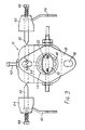
- the device 10 comprises a main body 12 through which passes an air/fuel supply passage 14. At its lower end the body 12 is provided with a flange 16 having suitable bolt holes 18 whereby it may be secured to the inlet manifold of a petrol fueled spark ignition engine of a motor vehicle (both not shown). Air is supplied preferably through an air filter (not shown) in conventional manner.
- the passage 14 At its lower end the passage 14 is provided with a butterfly valve 20 mounted on a pivot shaft 22 which is connected to a linkage (not shown) to the accelerator pedal of the vehicle. Mounted on the shaft 22 is an eccentric member 24 which is engagable by the ends of screw stop members 26 and 28 passing through plates 30 and 32 respectively on the body 12 and being adjustable to limit the movement of the eccentric member 24 and hence the butterfly valve 20.
- the body 12 has an enlargement 34.
- a petrol inlet 36 is provided on this enlargement through which petrol is supplied into an internal space 38 (see Figure 4 ' ) which is connected to a liquid supply toroid 40 by means to be described.
- the space 38 also is connected to a petrol return nipple 42 for recycling petrol to the petrol tank.
- the space 38 has a pair of ports 44 and 46 leading therefrom into a control passage 48.
- the sum of the cross-sectional areas of the passages 44 and 46 is equal to the cross-sectional area of the outlet pipe 42.
- Within the control passage 48 are two needle valves 50 and 52 having eccentric conical ends and which control respectively the ports 44 and 46.
- a spring 54 acts between the ends of these needle valves 50 and 52.
- An outlet port is provided in the control passage 48 leading to a petrol passage 56 that leads to the toroid 40.
- the needle valves 50 and 52 are carried respectively by levers 58 and 60 which pivot about the needle valve axes.
- Lugs 62 and 64 carry respectively adjusting screws 66 and 68 that act respectively on the needle valves 50 and 52 to move these inwardly and outwardly thereby controlling the setting of these valves.
- Each lever 58 and 60 is provided with four connecting holes 58a and 60a so that the control devices therefor (which will be described) can be connected at any desired distance away from the pivot axis of the lever.
- the device 70 has an inlet pipe 72 which is connected via flexible tubing 74 to a metal tube 76 brazed on to the body 12 and leading to a port 81 in the passage 14 at the level of the butterfly valve 20.
- the lifter device 70 has a piston rod or leg 78 connected to the diaphragm (not shown) in conventional manner and being secured by means of a pin 80 in one of the holes 58a in the lever 58.
- a short lever 82 is mounted on the butterfly valve shaft 22. This lever 82 is connected by a "S"-shaped rod member 84 to one of the holes 60a in the lever 60.
- connection between the lifting device 70 and link 58 is such that when there is maximum vacuum in the passage 14, the needle valve 50 will be so rotated that it will permit the maximum petrol flow through the port 44 and hence the toroid 40. Conversely when there is minimum or no flow through the passage 14 there will be minimum or no flow through the passage 44.
- the connection between the levers 82 and 60 is such that when the butterfly valve 20 is opened to its maximum extent the needle valve 52 will permit the maximum petrol flow through the port 46 and conversely when the butterfly valve is closed or substantially closed there will be no or little petrol flow through the passage 46.
- a water inlet control device 86 Bolted on to the projection 34 of the body 12 on the side thereof opposite to the petrol inlet 36 is a water inlet control device 86.
- This device 86 includes a jacketted water pipe 88 and within this jacket there is a heating coil (indicated generally at 90) to heat such water. Water from the device 86 enters into a bore 92 in the body 12.
- a valve 94 is provided to vary the flow area through the passage 92.
- the passage 92 is connected to the hollow toroid 40 diametrically opposite to the passage 56.
- a suitable overflow valve (indicated generally at 96) is provided in the passage 92 to return excess water from the passage 92 upstream of the needle valve 94 to the tank.
- One terminal of the heating coil 90 is earthed to the body 12, the other terminal of the coil 90 is connected to a moving contact 98 of a potentiometer 100 that is connected to the motor vehicle battery (not shown).
- the moving contact 98 is mounted on the lever 60 to be movable therewith.
- a relay control switch (not shown) is provided in the line between the potentiometer 100 and the vehicle battery.
- This control switch is operable so that the connection between the potentiometer 100 and the vehicle battery will be broken except when e.g. the ignition switch is turned into the operative condition.
- the toroid 40 is provided on its inner side with about eight pin hole size apertures equi-spaced thereabout through which the water/petrol mixture can be discharged into the passage 14.
- the heater 90 is arranged so that it will raise the temperature of the water being supplied to the toroid 40 slightly, of the order of five degrees celsius.
- the water and petrol supply will both be provided with conventional water and petrol pumps in the usual way.
- the screws 66 and 68 will be adjusted to set the position of the needle valves 50 and 52 respectively.
- the needle valve 94 will be adjusted for the appropriate supply of water.
- electrical power will be supplied to the heater 90.
- the butterfly valve 20 will be opened and at the same time the lever 60 will be rotated in a clock-wise direction (as shown in Figure 2).
- the butterfly valve will be moved to an appropriate running position and the positions of the needle valves 50 and 52 will be adjusted accordingly. If the passage 44 and 46 are obturated to such a degree that the petrol being supplied cannot pass therethrough, this petrol will escape via the passage 48 as described above.
- the above described mixing device 10 when connected to a conventional spark ignition internal combustion engine in a motor vehicle will give considerably improved petrol consumption as compared to the petrol consumption obtained with a conventional carburettor. Furthermore the device 10 gives a better consumption than even fuel injection engines of the same size. This improved consumption, it has been found, occurs without any loss of power.
- toroid may be replaced by an annular chamber cut into the body 12 about the air passage 14 and having an appropriate number of pin hole nozzles for the petrol/water mixture to enter into the passage 14.
- the number of such nozzles both in the modification and in the particular example as described above may be varied as desired.
- suitable protective housings may be provided particularly on the side of the device 10 illustrated in 2 to protect inter-alia the potentiometer 100.
Landscapes
- Engineering & Computer Science (AREA)
- Chemical & Material Sciences (AREA)
- Combustion & Propulsion (AREA)
- Mechanical Engineering (AREA)
- General Engineering & Computer Science (AREA)
- Health & Medical Sciences (AREA)
- Public Health (AREA)
- Water Supply & Treatment (AREA)
- Multiple-Way Valves (AREA)
- Control Of The Air-Fuel Ratio Of Carburetors (AREA)
Applications Claiming Priority (2)
| Application Number | Priority Date | Filing Date | Title |
|---|---|---|---|
| ZA800328 | 1980-01-21 | ||
| ZA80328 | 1980-01-21 |
Publications (1)
| Publication Number | Publication Date |
|---|---|
| EP0032849A1 true EP0032849A1 (de) | 1981-07-29 |
Family
ID=25574498
Family Applications (1)
| Application Number | Title | Priority Date | Filing Date |
|---|---|---|---|
| EP81300272A Withdrawn EP0032849A1 (de) | 1980-01-21 | 1981-01-21 | Vergaser |
Country Status (5)
| Country | Link |
|---|---|
| US (1) | US4344389A (de) |
| EP (1) | EP0032849A1 (de) |
| JP (1) | JPS56138454A (de) |
| AU (1) | AU6650481A (de) |
| GB (1) | GB2067659A (de) |
Families Citing this family (1)
| Publication number | Priority date | Publication date | Assignee | Title |
|---|---|---|---|---|
| JP2010065653A (ja) * | 2008-09-12 | 2010-03-25 | Ito Racing Service Co Ltd | 燃料供給装置用混合器 |
Citations (7)
| Publication number | Priority date | Publication date | Assignee | Title |
|---|---|---|---|---|
| DE387731C (de) * | 1924-01-03 | Carl Wirsum | Vergaser | |
| CH150081A (de) * | 1930-01-27 | 1931-10-15 | Levy Nestor | Verfahren und Vorrichtung zur Verbesserung der Vergasung und der Verbrennung von Treibstoffen durch Mischen derselben mit Wasserdampf. |
| CH216038A (de) * | 1940-08-30 | 1941-07-31 | Boden O M | Vergaser für mittel- und schwerflüchtige Brennstoffe. |
| DE2234764A1 (de) * | 1971-07-16 | 1973-01-25 | Max Yves Antonin Marie Serruys | Abgas-entgiftungsanlage fuer verbrennungsmotoren |
| DE2360681A1 (de) * | 1973-12-05 | 1975-06-19 | Buss Geb Rzymkowski | Vorrichtung zur erzeugung von treibstoff-wasser-emulsionen |
| DE2520604A1 (de) * | 1975-05-09 | 1976-11-18 | Bernd Beer | Beimischung von wasser mittels verneblungsanlage zur verbrennungsluft fuer ottomotoren bei aeusserer gemischbildung |
| DE2835099A1 (de) * | 1977-08-10 | 1979-03-01 | Cadbury Schweppes Ltd | Treibstoffsystem fuer einen dieselmotor |
Family Cites Families (8)
| Publication number | Priority date | Publication date | Assignee | Title |
|---|---|---|---|---|
| GB258866A (en) | 1925-09-23 | 1927-08-11 | Frank Lioud | Improvements in carburetters |
| GB263529A (en) | 1925-09-28 | 1926-12-28 | Andrew Fraser | Improvements in or relating to means for introducing water into the combustion chamber of a petrol engine |
| GB726534A (en) | 1949-11-07 | 1955-03-23 | Raymond Wilson Dunster | Improvements in means for admitting supplementary fuel to the carburettors of internal combustion engines |
| US3606868A (en) * | 1970-05-14 | 1971-09-21 | Maarten Voodg | Smog control system employing an emulsion of water in gasoline |
| US4005683A (en) * | 1974-10-07 | 1977-02-01 | Raymond Douglas Whitt | Energy conversion device |
| US4145998A (en) * | 1976-07-30 | 1979-03-27 | Econo Fuel Systems, Inc. | Hot fuel gas generator |
| US4166435A (en) * | 1978-04-11 | 1979-09-04 | Kiang Deh J | Internal combustion engines |
| US4259021A (en) * | 1978-04-19 | 1981-03-31 | Paul R. Goudy, Jr. | Fluid mixing apparatus and method |
-
1980
- 1980-03-05 GB GB8007527A patent/GB2067659A/en not_active Withdrawn
- 1980-03-10 US US06/128,898 patent/US4344389A/en not_active Expired - Lifetime
-
1981
- 1981-01-21 AU AU66504/81A patent/AU6650481A/en not_active Abandoned
- 1981-01-21 EP EP81300272A patent/EP0032849A1/de not_active Withdrawn
- 1981-01-21 JP JP776481A patent/JPS56138454A/ja active Pending
Patent Citations (7)
| Publication number | Priority date | Publication date | Assignee | Title |
|---|---|---|---|---|
| DE387731C (de) * | 1924-01-03 | Carl Wirsum | Vergaser | |
| CH150081A (de) * | 1930-01-27 | 1931-10-15 | Levy Nestor | Verfahren und Vorrichtung zur Verbesserung der Vergasung und der Verbrennung von Treibstoffen durch Mischen derselben mit Wasserdampf. |
| CH216038A (de) * | 1940-08-30 | 1941-07-31 | Boden O M | Vergaser für mittel- und schwerflüchtige Brennstoffe. |
| DE2234764A1 (de) * | 1971-07-16 | 1973-01-25 | Max Yves Antonin Marie Serruys | Abgas-entgiftungsanlage fuer verbrennungsmotoren |
| DE2360681A1 (de) * | 1973-12-05 | 1975-06-19 | Buss Geb Rzymkowski | Vorrichtung zur erzeugung von treibstoff-wasser-emulsionen |
| DE2520604A1 (de) * | 1975-05-09 | 1976-11-18 | Bernd Beer | Beimischung von wasser mittels verneblungsanlage zur verbrennungsluft fuer ottomotoren bei aeusserer gemischbildung |
| DE2835099A1 (de) * | 1977-08-10 | 1979-03-01 | Cadbury Schweppes Ltd | Treibstoffsystem fuer einen dieselmotor |
Non-Patent Citations (2)
| Title |
|---|
| AUTOMOTIVE ENGINEERING, Vol. 87, No. 5, May 1979 New York D. SCOTT " Water Injection Raises Turbocharging Capacity" * Pages 84 and 85 * * |
| MARINE ENG. REVIEUW, No. 4, April 1979 London R.V. YHOMPSON "Water-emulsified Fuels: Part 2 - Internal Combustion Engines * * Pages 12 to 14 * * |
Also Published As
| Publication number | Publication date |
|---|---|
| GB2067659A (en) | 1981-07-30 |
| AU6650481A (en) | 1981-07-30 |
| JPS56138454A (en) | 1981-10-29 |
| US4344389A (en) | 1982-08-17 |
Similar Documents
| Publication | Publication Date | Title |
|---|---|---|
| US5450832A (en) | Dual fuel system | |
| US4112889A (en) | Fuel system and vaporizer for internal combustion engines | |
| US4574763A (en) | Dual fuel carburetion system and method | |
| US4151821A (en) | Engine fuel supply system | |
| US4398523A (en) | Fuel conservation device | |
| EP0073238A4 (de) | Vergasersystem für zwei brennstoffe, sowie verfahren dazu. | |
| US4106453A (en) | Apparatus and process for improving fuel efficiency of an internal combustion engine utilizing a vapor state of fuel | |
| US4005683A (en) | Energy conversion device | |
| US5213086A (en) | Fuel inlet system for internal combustion engine | |
| US4499887A (en) | Dual fuel supply system | |
| US4348338A (en) | Injection-type pressure-freed carburetor | |
| KR920006544B1 (ko) | 압축 착화엔진의 벤츄리장치 및 이것을 이용한 무화(fumigation)시스템 | |
| US4375795A (en) | Dual fuel supply system | |
| US4197819A (en) | Hot fuel gas generator | |
| US4423716A (en) | Fuel system for internal combustion engines | |
| US3443551A (en) | Diesel engine propane accessory | |
| EP0055288A1 (de) | Flüssiggaszufuhrsystem | |
| US5007402A (en) | Intake system for a mixture-compressing internal-combustion engine | |
| US3695589A (en) | Air valve carburetor | |
| US4344389A (en) | Fuel/air mixing device | |
| US4452215A (en) | Fuel system for internal combustion engines | |
| US4305350A (en) | Dual fuel system | |
| US4246879A (en) | Fuel injection apparatus | |
| US4512323A (en) | Carburetor vaporizer | |
| US4670194A (en) | Carburetor |
Legal Events
| Date | Code | Title | Description |
|---|---|---|---|
| PUAI | Public reference made under article 153(3) epc to a published international application that has entered the european phase |
Free format text: ORIGINAL CODE: 0009012 |
|
| AK | Designated contracting states |
Designated state(s): DE FR GB IT |
|
| STAA | Information on the status of an ep patent application or granted ep patent |
Free format text: STATUS: THE APPLICATION IS DEEMED TO BE WITHDRAWN |
|
| 18D | Application deemed to be withdrawn |
Effective date: 19820708 |
|
| RIN1 | Information on inventor provided before grant (corrected) |
Inventor name: NUNES, ANIZIO GERALDES ROQUE |