EP0032852A2 - System zum Behandeln und Messen von Signalen, die von jedem Detektor in einem Modulationsspektrometer abgegeben werden - Google Patents
System zum Behandeln und Messen von Signalen, die von jedem Detektor in einem Modulationsspektrometer abgegeben werden Download PDFInfo
- Publication number
- EP0032852A2 EP0032852A2 EP81400011A EP81400011A EP0032852A2 EP 0032852 A2 EP0032852 A2 EP 0032852A2 EP 81400011 A EP81400011 A EP 81400011A EP 81400011 A EP81400011 A EP 81400011A EP 0032852 A2 EP0032852 A2 EP 0032852A2
- Authority
- EP
- European Patent Office
- Prior art keywords
- converter
- detector
- supplied
- filter
- amplification chain
- Prior art date
- Legal status (The legal status is an assumption and is not a legal conclusion. Google has not performed a legal analysis and makes no representation as to the accuracy of the status listed.)
- Withdrawn
Links
- 230000003321 amplification Effects 0.000 claims abstract description 38
- 238000003199 nucleic acid amplification method Methods 0.000 claims abstract description 38
- 239000010453 quartz Substances 0.000 claims description 13
- VYPSYNLAJGMNEJ-UHFFFAOYSA-N silicon dioxide Inorganic materials O=[Si]=O VYPSYNLAJGMNEJ-UHFFFAOYSA-N 0.000 claims description 13
- 230000001360 synchronised effect Effects 0.000 claims description 10
- 229910052736 halogen Inorganic materials 0.000 claims description 4
- 150000002367 halogens Chemical class 0.000 claims description 4
- HBMJWWWQQXIZIP-UHFFFAOYSA-N silicon carbide Chemical compound [Si+]#[C-] HBMJWWWQQXIZIP-UHFFFAOYSA-N 0.000 claims description 4
- 229910010271 silicon carbide Inorganic materials 0.000 claims description 4
- 239000013078 crystal Substances 0.000 claims description 3
- 238000005259 measurement Methods 0.000 description 35
- 238000001514 detection method Methods 0.000 description 7
- 239000003990 capacitor Substances 0.000 description 4
- 230000005679 Peltier effect Effects 0.000 description 3
- 238000010586 diagram Methods 0.000 description 3
- XUIMIQQOPSSXEZ-UHFFFAOYSA-N Silicon Chemical compound [Si] XUIMIQQOPSSXEZ-UHFFFAOYSA-N 0.000 description 2
- 238000006243 chemical reaction Methods 0.000 description 2
- 229910052710 silicon Inorganic materials 0.000 description 2
- 239000010703 silicon Substances 0.000 description 2
- 238000010521 absorption reaction Methods 0.000 description 1
- 238000004458 analytical method Methods 0.000 description 1
- 150000001875 compounds Chemical class 0.000 description 1
- 230000000694 effects Effects 0.000 description 1
- 238000001914 filtration Methods 0.000 description 1
- 230000031700 light absorption Effects 0.000 description 1
- 230000003287 optical effect Effects 0.000 description 1
- 230000005855 radiation Effects 0.000 description 1
- 239000002904 solvent Substances 0.000 description 1
- 230000001052 transient effect Effects 0.000 description 1
Images


Classifications
-
- G—PHYSICS
- G01—MEASURING; TESTING
- G01N—INVESTIGATING OR ANALYSING MATERIALS BY DETERMINING THEIR CHEMICAL OR PHYSICAL PROPERTIES
- G01N21/00—Investigating or analysing materials by the use of optical means, i.e. using sub-millimetre waves, infrared, visible or ultraviolet light
- G01N21/17—Systems in which incident light is modified in accordance with the properties of the material investigated
- G01N21/25—Colour; Spectral properties, i.e. comparison of effect of material on the light at two or more different wavelengths or wavelength bands
- G01N21/31—Investigating relative effect of material at wavelengths characteristic of specific elements or molecules, e.g. atomic absorption spectrometry
- G01N21/314—Investigating relative effect of material at wavelengths characteristic of specific elements or molecules, e.g. atomic absorption spectrometry with comparison of measurements at specific and non-specific wavelengths
-
- G—PHYSICS
- G01—MEASURING; TESTING
- G01J—MEASUREMENT OF INTENSITY, VELOCITY, SPECTRAL CONTENT, POLARISATION, PHASE OR PULSE CHARACTERISTICS OF INFRARED, VISIBLE OR ULTRAVIOLET LIGHT; COLORIMETRY; RADIATION PYROMETRY
- G01J1/00—Photometry, e.g. photographic exposure meter
- G01J1/10—Photometry, e.g. photographic exposure meter by comparison with reference light or electric value provisionally void
- G01J1/16—Photometry, e.g. photographic exposure meter by comparison with reference light or electric value provisionally void using electric radiation detectors
Definitions
- the present invention relates to a system for processing and measuring the signals delivered by each detector, in a spectrometer with light beam modulation. It applies to the simplification of modulation spectrometers intended for example for the simultaneous determination of several compounds dissolved in a solvent.
- some include a light source associated with means which make it possible to divide the light beam from the source, into several beams, some of reference, others of measurement; the bundles of. measure through the sample.
- the energies of the reference and measurement beams are measured over very short periods. These periods correspond to the modulation frequency of the beams; this modulation is carried out by electro-optical means which are generally constituted by a rotating disc, carrying alternating opaque and transparent sectors, moving so as to cut the two beams.
- the energy transmitted by the sample and the energy of the reference beam are detected by electro-optical detection means which are associated with measurement means making it possible to measure the difference in the energies of the reference and measurement beams, and thus to determine the greater or lesser light absorption of the sample.
- These absorption measurements can be carried out at different wavelengths; it suffices to select, by appropriate means, the wavelengths of the reference and measurement beams, according to the sample to be studied.
- the means for detecting the energies of the reference and measurement beams comprise, for each wavelength selected, a photoelectric detector, sensitive to this wavelength and for each of these detectors, an amplification chain of the signal from the corresponding detector; the output of this chain is connected to the measuring means. These detectors alternately receive the reference and measurement beams by means of the modulation means described above.
- the spectrometers which are mentioned above are two-channel spectrometers (acting at two wavelengths ⁇ 1 and A 2) and double beam (one for reference, the other for measurement), or spectrometers for a single channel (acting at one wavelength) and double beam.
- spectrometric analyzers which make it possible to analyze samples, in particular in the infrared domain, implement, a preamplification of the signal supplied by an infrared detector and a synchronous detection carried out by means of a synchronization signal taken from the means for modulating the reference and measurement beams.
- This synchronous detection has a major drawback: it greatly complicates the circuits for processing and measuring the signals from the detectors and consequently makes the spectrometers which use it very expensive.
- this synchronous detection requires that the noise has no phase relationship with the synchronization signal from the modulation means; finally, the time constant of the filtering carried out after synchronous detection of the measurement and reference beams, must be greater than the period of fluctuation of the lower frequency of the noise.
- the object of the invention is to remedy these drawbacks and in particular to simplify the circuits for processing and measuring the signals from the detectors. in a light beam modulation spectrometer. It also makes it possible to avoid adding to the detection means, a filter having a too long temple constant, thanks to the use of an active electric filter.
- the subject of the invention is a system for processing and measuring the signals delivered by each detector, in a spectrometer with modulation of light beams, comprising for each detector, a chain of amplification of the signals delivered by this detector and means for measurement, connected at the output of each amplification chain; this system is characterized in that the amplification chain comprises at least one selective amplifier, tuned to the modulation frequency of the beams.
- the amplification chain further comprises an active electric filter, tuned to a frequency twice the frequency of modulation of the beams, this filter is connected between the output of the corresponding amplifier and the means of measurement.
- the spectrometer comprising means for modulating the beams constituted by a rotating disc having opaque and transparent sectors alternating in front of each of the beams, the system comprises means for driving the disc in rotation, these means being controlled by an oscillator quartz.
- the drive means of the rotating disc comprise a synchronous motor supplied by an alternating direct converter controlled by the crystal oscillator, this converter being supplied by an electric source of direct current.
- the converted AC alternator controlled by the crystal oscillator also supplies the amplification chain, via an AC-DC converter.
- the drive means of the rotating disc comprise a stepping motor supplied by an AC-DC converter, via a logic control circuit, controlled by the quartz oscillator.
- the light beams are produced by a light source, of the halogen type or of the "silicon carbide" type.
- the DC-AC converter controlled by the quartz oscillator further supplies at least one of the detectors via an AC-DC converter.
- said detector is further supplied by a current generator, itself supplied by the electrical source of direct current.
- an alternative-DC converter supplies at least one of the detectors.
- the AC-DC converter supplies the detector via a current generator.
- the AC-DC converter supplies the detector via a DC-DC converter.
- the AC-DC converter supplies the amplification chain.
- the AC-DC converter is supplied by a "Backup" type line.
- FIG. 1 represents an embodiment of a system according to the invention and allowing the processing and measurement of the signals delivered by each detector 2, 3 in a spectrometer 1, with modulation of light beams emitted by a light source 4 constituted preferably, by a very stable halogen type lamp or by a silicon carbide lamp con.nue under the trade name "GLOBAR".
- the spectrometer represented schematically at 1 in the figure, is for example, a two-channel spectrometer, of known type, comprising in particular two detectors 2, 3 sensitive respectively to two different wavelengths.
- This spectrometer also includes means, not shown, which make it possible to divide the beam of source light, in reference and measurement beams. In known manner, the measurement beam crosses a sample to be analyzed and the difference in energies between the reference and measurement beams is measured.
- the spectrometer comprises modulation means, constituted by a rotating disc 6, driven by a motor 7 and having alternating opaque and transparent sectors.
- the detectors 2, 3 make it possible to detect the energies of the reference and measurement beams, for each of the wavelengths selected in the spectrometer. These detectors alternately receive the reference and measurement beams, thanks to the alternating opaque and transparent sectors of the rotating disc 6. It is obvious that the number of these detectors has been limited to two, but that it could be different.
- the processing and measurement system comprises amplification chains 8, 9 connected at the output of each of the detectors, and measurement means 10, connected to the outputs of amplification chains 8, 9.
- These Amplification chains can of course allow observation of the analysis curves on an oscilloscope 11.
- the wavelengths selected in the spectrometer naturally correspond to the components of the sample which respectively absorb radiation in these wavelengths.
- each detector alternately receives the light transmitted by the sample and the light from the reference beam.
- the detectors 2, 3 therefore deliver alternating signals phase shifted for example by 180 ° or 90 °, depending on whether the rotating disc has two or four sectors.
- the amplification chains 8, 9 are synchronized with the signal supplied by a optical detector for example, located opposite the rotating disc 6.
- this main type of synchronization has the main drawback of making the measurements very sensitive to the noise which accompanies the measurement signals, this noise possibly being in phase with modulation signals.
- this synchronization complicates the processing and measurement circuits associated with the spectrometer.
- the amplification chain which is associated with each of the detectors comprises at least one selective amplifier, tuned to the modulation frequency of the reference and measurement beams.
- This amplification chain will be described later in detail. Its main advantage, as mentioned above, is to eliminate any synchronization from a detection of the frequency of the rotating disc.
- each amplification chain further comprises an active electric filter, tuned to the frequency twice the beam modulation frequency and connected between the output of each amplifier and the measurement means 10.
- the motor 7 which drives the rotating disc 6, is of the synchronous type, powered by t, n DC-converter 12 controlled by a quartz oscillator 13. This motor can also be a stepping motor piloted by quartz.
- This DC-to-AC converter is itself supplied by a direct current electrical source 14.
- This direct current electrical source can be constituted either by a stabilized DC power supply 15, itself supplied by the AC mains voltage 16 , or by a storage battery 17.
- a switch 18 with two positions, controllable either electrically or manually, makes it possible to supply the various means of the processing and measurement system, from the storage battery 17 in the event of a mains failure 16.
- the stabilized power source 15 as well as the DC-AC converter 12 controlled by the quartz oscillator 13 are conventional in the state of the art and will not be described in more detail.
- the converter also supplies the amplification chains 8, 9 via an alternating-continuous converter 19.
- the light source 4 is supplied directly by the stabilized supply 14.
- the stabilized power supply 15 is a 220 V AC power supply - 24 V DC
- the DC-AC converter 12 is a 24 V DC-220 V AC converter
- the AC-DC converter 19 is a 220V AC - 15 V DC converter.
- infrared detectors are used which have a very high signal / noise ratio, in a range of lengths d fairly narrow wave.
- the detector 3 is a Se-Pb detector, having a pass band ranging from 3 to 7 microns, cooled by the Peltier effect.
- Detector 2 is a silicon PIN type photodiode which has a passband of less than 1 micron.
- the detector 3 is supplied by the DC-AC converter 12, via an AC-DC converter 20 which supplies this detector with a DC voltage of 90 V for example, and via a current generator 21 supplied by the electric source 14 of direct current. This current generator cools the detector 3 by effect. Peltier.
- the amplification chains comprise at least one selective amplifier, tuned to the modulation frequency of the reference and measurement beams.
- the amplification chains as will be seen below, are simple since they use circuits with an operational amplifier.
- the circuits which intervene in the amplification chains 8, 9 are shown in more detail and which comprise, first of all, an impedance adapter 24 constituted by a conventional assembly with an operational amplifier, powered by a DC voltage of 15 V delivered by the AC-DC converter 19.
- the input 25 of this impedance adapter is connected, either directly to the output of the detector 2, for the amplification chain 8, or to the output of a preamplifier, not shown and constituted in a known manner, for the amplification chain 9 which is connected to the output of the detector 3.
- the operational amplifier 26 is supplied by a DC voltage of + 15 V, supplied by the ac-dc converter 19; the other elements of this adapter which is constituted in a known manner, are not referenced in FIG. 2.
- the output 27 of the adapter 24 is connected to the input 28 of a selective amplifier 29, the central band of which is 30 Hertz for example, in the embodiment of the system according to the invention.
- This selective amplifier also constituted in a known manner, comprises an operational amplifier 30 supplied with a DC voltage of + 15 V supplied by the AC-DC converter 19. The other elements of this selective amplifier constituted in known manner are not referenced on the face.
- the output 31 of the amplifier 29 is connected to the input 32 of a dual-cycle detector 33, by means of a decoupling capacitor 34.
- This detector is itself constituted in a known manner by a circuit comprising two operational amplifiers 35, 36 and diodes 27, 38 as well as other elements not referenced in the figure.
- the operational amplifiers are supplied by a DC voltage + 15 V supplied by the AC-DC converter 19.
- the output 39 of the detector 33 can be connected to the input of the measuring means 10, for example by the through an active band rejector filter 40, called “double T rejector", which allows, for example, to eliminate the 60 Hertz component from the voltage supplied by the amplification chain; this band rejector filter is constituted in a known manner: its elements are not referenced in the figure.
- Its output 41 can be connected to the input of the measurement means 10, for example by means of an impedance adapter amplifier 42 and a filter 43, which are formed in known manner and whose elements do not have not been referenced in the figure.
- the band rejector filter causes a rejection at 60 Hertz, which makes it possible to use, as measurement means 10, a conventional voltmeter, of continuous type.
- the selective amplifier tuned to the modulation frequency of the reference and measurement beams, makes it possible to increase the value of the signal / noise ratio while the active filter tunable on the frequency double the beam modulation frequency also allows '' eliminate any annoying noise in the signal used.
- the modulation frequency is very stable, since the motor 7 which drives the rotating disc 6, is a synchronous motor supplied by the DC-AC converter 12 controlled by the quartz oscillator 13.
- all the circuits and means represented are powered by via a storage battery or a single power source, which prevents any amplitude or frequency disturbance, which is particularly important for medical applications of the spectrometer.
- the use on one of the tracks of a detector 3 cooled by Peltier effect, thanks to the current generator 21, allows to control in a simple way the gain on this track, which can be very interesting, in particular for the setting in spectrometer service.
- this spectrometer thanks to the system of the invention, can operate autonomously on the storage battery 17.
- the various converters -as well as the current generator, which are constituted in known manner, are not not described in detail.
- FIG. 3 there is shown another embodiment of the system of the invention, applied to a beam modulation spectrometer, to a channel.
- the same elements have the same references in this figure and in Figure 1.
- the spectrometer which in this embodiment is a beam modulation spectrometer, with a single channel and which comprises in particular a detector 3 and a light source 4, comparable to the detector and to the source of the spectrometer in FIG. 1.
- the amplification chain is shown at 9, the details of which are given in FIG.
- the rotating disc 5 which comprises alternating transparent and opaque sectors 6 is driven by means 7 constituted by a motor, controlled by the quartz oscillator 13.
- the motor is of the stepping type, supplied by a DC alternating converter 50 via a logic control circuit 5t, controlled by the quartz oscillator 13
- This DC alternating converter supplies the detector 3 via the current generator 21 and via a DC-DC converter 52.
- the amplification chain 9 It also supplies the amplification chain 9; It is obvious that in this embodiment, the spectrometer being a single channel, a single amplification chain is shown in the diagram.
- the DC alternating converter 50 is supplied at 52 by a line not shown, which can be of the "Back-up” type, in the event of a network failure on which this line is connected.
- This line of the “emergency” type is not shown in detail but it is known in the state of the art, to use a backup system, in the event of a network failure.
- the spectrometer comprises a single detector which can be a Pb-Se detector, cooled by the Peltier effect, sensitive to a wavelength of four microns, as in the first embodiment.
- the light source 4 can be, as in the first embodiment, a halogen type source or a silicon carbide source, known under the trade name "GLOBAR".
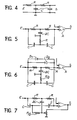
- FIG. 4 represents a conventional low-pass filter of order 2.
- This filter is not used in the invention because it has drawbacks. It is however used at the output of conventional synchronous detectors to filter the output signals of these detectors. It consists of the cascading of two filters of order I (filter and post-filter).
- One of the objects of the invention is to highlight the fact that on rejection of the equal residual ripple, a tuned rejector (double T) allows a shorter response time, or what is equivalent, that with equal response time, the rejection of the residual ripple provided by a tuned rejector is better.
- the response time of this filter is T 2 RC.
- FIG. 5 is an equivalent diagram of the double T rejector filter, 40, of FIG. 2, followed by the operational amplifier A of the adapter circuit of impedance 42.
- the resistors and capacitors have been designated by the values respective R, R / 2, C, 2C.
- the double T rejector filter shown in FIG. 6 and which can be used in the invention, it is possible to reduce the response time of the double T rejector without altering its rejection qualities, by the use of two antiparallel diodes whose impedance is very high if the amplitude of the input signal (D 1 , D 2 ) (residual ripple) is less than their threshold voltage (0.6V for silicon diodes IN4T48), and becomes weak, thus canceling the filter time constant, if the input voltage varies by more than 0.6V for a time less than the time constant of the double T network.
- R, R / 2, C and 2C denote the values of the corresponding resistors and capacitors.
- FIG. 7 shows another embodiment of the double T rejector filter, which can be used in the invention.
- a variable reaction is introduced at the base of the double-T rejector, by re-injecting part of the output voltage of the operational amplifier. This reaction actually increases the overvoltage coefficient of the rejector which then becomes a real active filter.
Landscapes
- Physics & Mathematics (AREA)
- Spectroscopy & Molecular Physics (AREA)
- General Physics & Mathematics (AREA)
- Biochemistry (AREA)
- Chemical & Material Sciences (AREA)
- Analytical Chemistry (AREA)
- Life Sciences & Earth Sciences (AREA)
- General Health & Medical Sciences (AREA)
- Health & Medical Sciences (AREA)
- Immunology (AREA)
- Pathology (AREA)
- Investigating Or Analysing Materials By Optical Means (AREA)
- Spectrometry And Color Measurement (AREA)
Applications Claiming Priority (2)
| Application Number | Priority Date | Filing Date | Title |
|---|---|---|---|
| FR8001073 | 1980-01-18 | ||
| FR8001073A FR2474165A1 (fr) | 1980-01-18 | 1980-01-18 | Systeme de traitement et de mesure des signaux delivres par chaque detecteur dans un spectrometre a modulation |
Publications (2)
| Publication Number | Publication Date |
|---|---|
| EP0032852A2 true EP0032852A2 (de) | 1981-07-29 |
| EP0032852A3 EP0032852A3 (de) | 1983-04-20 |
Family
ID=9237642
Family Applications (1)
| Application Number | Title | Priority Date | Filing Date |
|---|---|---|---|
| EP81400011A Withdrawn EP0032852A3 (de) | 1980-01-18 | 1981-01-07 | System zum Behandeln und Messen von Signalen, die von jedem Detektor in einem Modulationsspektrometer abgegeben werden |
Country Status (2)
| Country | Link |
|---|---|
| EP (1) | EP0032852A3 (de) |
| FR (1) | FR2474165A1 (de) |
Cited By (1)
| Publication number | Priority date | Publication date | Assignee | Title |
|---|---|---|---|---|
| EP0076356A1 (de) * | 1981-09-22 | 1983-04-13 | H. Maihak Ag | Verfahren und Vorrichtung zur Messung der Konzentration einer IR-, NDIR-, VIS- oder UV-Strahlung absorbierenden Komponente eines Komponentengemischs |
Family Cites Families (9)
| Publication number | Priority date | Publication date | Assignee | Title |
|---|---|---|---|---|
| GB909445A (en) * | 1960-01-18 | 1962-10-31 | Perkin Elmer Ltd | Improvements relating to optical null systems |
| CH366891A (fr) * | 1960-05-25 | 1963-01-31 | Haeberli Peter | Procédé pour le démarrage et le réglage de la vitesse d'une machine électrique synchrone et installation pour la mise en oeuvre de ce procédé |
| US3312885A (en) * | 1964-01-16 | 1967-04-04 | Ampex | Motor drive apparatus |
| US3405268A (en) * | 1965-03-12 | 1968-10-08 | Brun Sensor Systems Inc | Radiant energy absorption gage for measuring the weight of a base material and the content of a material sorbed by the base material |
| US3518516A (en) * | 1967-12-26 | 1970-06-30 | Ibm | Stepping motor constant velocity drive |
| DE2032195C3 (de) * | 1970-06-30 | 1978-05-03 | Erwin Sick Gmbh Optik-Elektronik, 7808 Waldkirch | Mehrkanal-Kolorimeter, insbesondere Durchflußkolorimeter |
| US3878107A (en) * | 1974-06-24 | 1975-04-15 | Philco Ford Corp | Electronically compensated rotating gas cell analyzer |
| FR2368708A1 (fr) * | 1976-10-20 | 1978-05-19 | Oreal | Appareil destine a mesurer une caracteristique optique d'un echantillon |
| DE2727976C3 (de) * | 1977-06-22 | 1980-05-29 | Kernforschungszentrum Karlsruhe Gmbh, 7500 Karlsruhe | Vorrichtung zur Messung der Konzentration mindestens einer Komponente eines Gasgemisches und Verfahren zum Eichen derselben |
-
1980
- 1980-01-18 FR FR8001073A patent/FR2474165A1/fr active Granted
-
1981
- 1981-01-07 EP EP81400011A patent/EP0032852A3/de not_active Withdrawn
Cited By (2)
| Publication number | Priority date | Publication date | Assignee | Title |
|---|---|---|---|---|
| EP0076356A1 (de) * | 1981-09-22 | 1983-04-13 | H. Maihak Ag | Verfahren und Vorrichtung zur Messung der Konzentration einer IR-, NDIR-, VIS- oder UV-Strahlung absorbierenden Komponente eines Komponentengemischs |
| US4641973A (en) * | 1981-09-22 | 1987-02-10 | H. Maihak Ag | Method and apparatus for measurement of the concentration of a component of a mixture |
Also Published As
| Publication number | Publication date |
|---|---|
| FR2474165A1 (fr) | 1981-07-24 |
| EP0032852A3 (de) | 1983-04-20 |
| FR2474165B1 (de) | 1983-10-14 |
Similar Documents
| Publication | Publication Date | Title |
|---|---|---|
| EP0635127B1 (de) | Verbessertes gerät und verfahren zur optischen messung der eigenschaften einer substanz | |
| FR2530024A1 (fr) | Microsonde a effet raman a laser | |
| EP0663590B1 (de) | Moduliertes Spektralellipsometer | |
| FR2588656A1 (fr) | Appareil de spectro-colorimetrie a fibres optiques | |
| WO2018102093A1 (en) | All-digital noise cancellation method for solid state spin-based sensors | |
| EP1565763B1 (de) | Verbesserte schaltungsanordnung für spektrometrie und spektrometrisches system, das diese anordnung verwendet | |
| EP0356302B1 (de) | Verfahren und Vorrichtung zur optischen Filterung und Photodetektion von intensitätsmodulierten Signalen | |
| FR2647552A1 (fr) | Systeme de mesure de signaux electriques a l'aide d'impulsions optiques ultracourtes | |
| CA2881524C (fr) | Dispositif d'amplification analogique destine notamment a un anemometre laser | |
| EP0670487B1 (de) | Verfahren und Vorrichtung zur Bestimmung der Absorption einer elektromagnetischen Strahlung durch ein Gas | |
| EP0032852A2 (de) | System zum Behandeln und Messen von Signalen, die von jedem Detektor in einem Modulationsspektrometer abgegeben werden | |
| US4218143A (en) | Lattice matching measurement device | |
| EP3767282A1 (de) | Vorrichtung und methode zur in-situ-messung der lebensdauer von minoritätsträgern in einem halbleitermaterial | |
| FR2769099A1 (fr) | Dispositif de mesure du temps de montee de signaux parasites par des bruits, provenant de detecteurs de rayonnements y ou x | |
| US20230084219A1 (en) | Systems and methods for photoreflectance spectroscopy using parallel demodulation | |
| CN114720403B (zh) | 一种高灵敏度超快吸收光谱仪 | |
| EP0159257B1 (de) | Schaltung zur Messung sehr schwacher auf hohem Potential liegender Signale | |
| EP0027758A1 (de) | Einrichtung zur automatischen Verstärkungsregelung durch optische Mittel in einem System zur Übertragung elektrischer Signale über eine optische Strecke | |
| EP0125171B1 (de) | Verfahren und Einrichtung zur Emissionsspektrometrischen Bestimmung des Inhalts an einem Element, wie etwa Aluminium, das in gelöstem und niedergeschlagenem Zustand in einem Metall, wie etwa Stahl vorkommt | |
| FR2951538A1 (fr) | Appareil de mesure spectrometrique de la diffusion inelastique de haute performance dans le domaine des basses frequences | |
| EP0495698B1 (de) | Verfahren und Gerät zur Prüfung paralellgeschalteter Dioden mit sichtbaren Übergängen | |
| FR2810108A1 (fr) | Ellipsometre spectroscopique a faible bruit | |
| EP4363814B1 (de) | Mehrphasige synchrone spektrometeranordnung für eine modulierte quelle optischer strahlung mit mehreren wellenlängen sowie zugehörige verfahren und verwendungen | |
| EP3447909A1 (de) | Verfahren und vorrichtung zur charakterisierung eines fotovoltaikmoduls | |
| US20120049880A1 (en) | Simultaneous qe scanning system and methods for photovoltaic devices |
Legal Events
| Date | Code | Title | Description |
|---|---|---|---|
| PUAI | Public reference made under article 153(3) epc to a published international application that has entered the european phase |
Free format text: ORIGINAL CODE: 0009012 |
|
| AK | Designated contracting states |
Designated state(s): CH DE GB IT NL |
|
| 17P | Request for examination filed |
Effective date: 19811215 |
|
| PUAL | Search report despatched |
Free format text: ORIGINAL CODE: 0009013 |
|
| AK | Designated contracting states |
Designated state(s): CH DE GB IT LI NL |
|
| STAA | Information on the status of an ep patent application or granted ep patent |
Free format text: STATUS: THE APPLICATION IS DEEMED TO BE WITHDRAWN |
|
| 18D | Application deemed to be withdrawn |
Effective date: 19850129 |
|
| RIN1 | Information on inventor provided before grant (corrected) |
Inventor name: ANITOFF, OLEG |